When you click on links to various merchants on this site and make a purchase, this can result in this site earning a commission. Affiliate programs and affiliations include, but are not limited to, the eBay Partner Network.
His instructions do say that a single resistor of 390 is good for 2 or 3 bulbs, but he has clarified that one resistor of 390 is not enough for 1 bulb to allow for brightness and long life. He is suggesting to me (I'm an 89 C4 owner, so I have a single backlit light for my AWD system that shines through a green mylar, and an occasional flashing bulb to indicate the AWD is active) that I use a higher resistance than the 390 for a single bulb, such as a 470 ohm 1/4W resistor.
I'll see what my local "The Source" electrical shop has tonight.
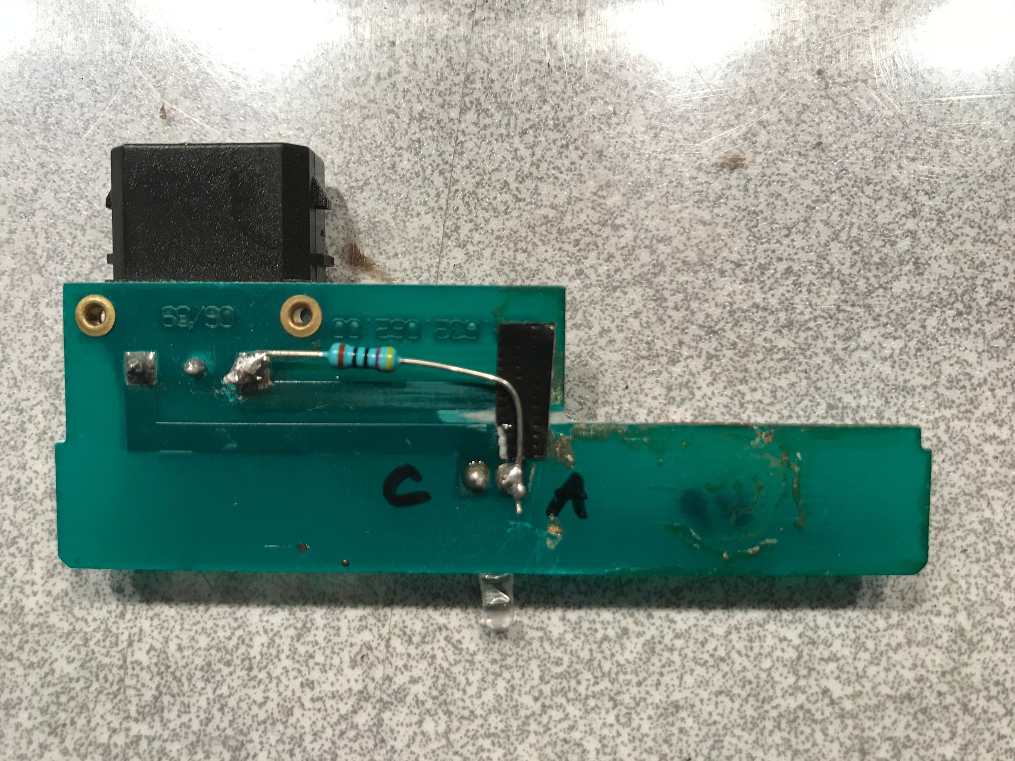
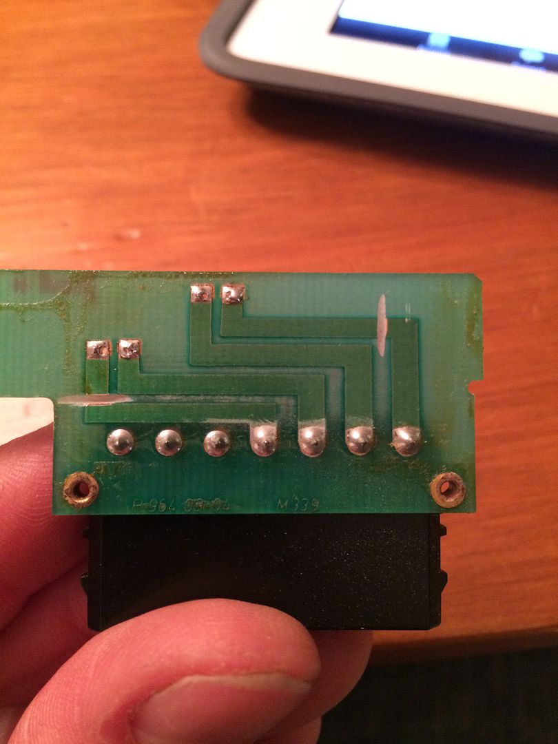
Having a C4, I followed vagluv's post above which indicated that pins 1 and 4 are hot (positive). However, on an 89 C4 with only one rotary **** for the AWD (the switch for the spoiler is under the deck lid), it is pins 2 and 3 that are positive and therefore receive the anode side of the LED (the longer wire). I finally figured this out and replaced my LEDs with new ones as the bends made them look awful. I cut the track on pins 1 and 4 and wired the resistor to this side and it works fine. I decided to go with a red LED on the flashing AWD light. Caution, using only a 390 ohm resistor on a single bulb is not going to let the LED last very long on a 2V LED. My local guy taught me a few things and we settled on a 600 ohm resistor I believe. Also went with the non carbon resistors as they are so small that you can place them anywhere on the PCB and not worry about them interfering with the plastic casing. I will post pics. A shout out to www.qkits.com in kingston ontario. Guy sold me my 2 LEDs and 2 resistors for $1. I gave him a five and told him to keep the change, and he ended up throwing in about 10 resistors and a bunch of red and green LEDs for the balance. Nice guy. First time meeting him. Ships world wide, no affil.
89 C4 with only one rotary **** Cut the tracks on 1 and 4. Easy and nice locations. Used a very thin dremel wheel Soldered the 600 ohm resistors to the same locations, but anodes on LEDs go to pin 2 and pin 3 as the receive positive power. The picture below shows it reversed, and I swapped the LED around after this pic was taken. Note the raised hump on the glass bulb on the anode side. The pic shows the anode on 1 and 4 and I needed to switch to 2 and 3 Ta da!!
I've bought Tore's kit for my 90 C4.
The top board is simple but I'm not certain what I am doing with the bottom board.
How do I use just the 1 resister for the bottom board containing 3 LEDs?
I just competed Tore's kit on my 1990 C2 Tiptronic. It has a unique lower board with one LED but with a bit of guessing based upon the 3 LED board I was able to figure out what is anode and what is cathode. It aligns to the same pin on both connectors.
Great kit Tore! I just ordered another one for my C4.
Hi,
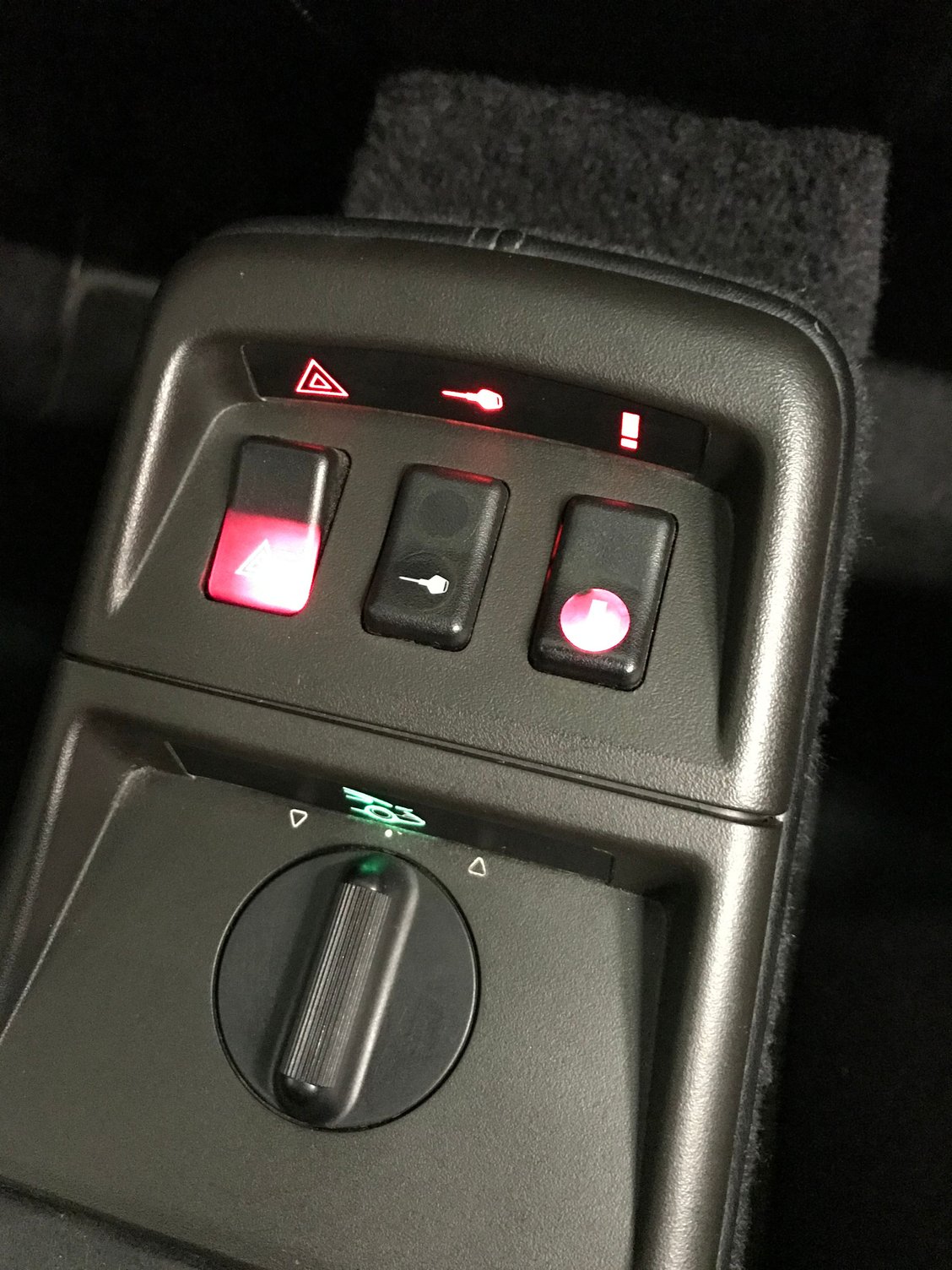
I fixed my console lights today.
I have a 1991 964 C2.
Many thanks to Tore for providing the kit!!!
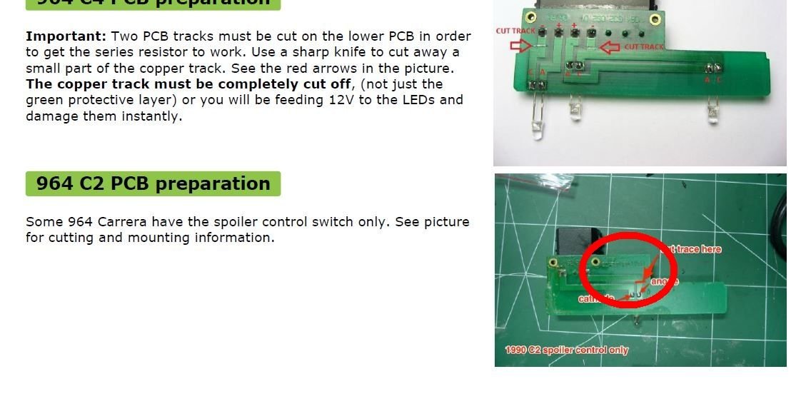
As RicardoD already showed in his pics the instructions provided by Tore are good, but for a 964 C2 a hint is missing... for the lower PCB with just 1 green LED (Spoiler) you need to add a resistor as well.
Finished work Resistor need to be added as well ... --- like this

 03-13-2015, 04:23 PM

 Soldered the 600 ohm resistors to the same locations, but anodes on LEDs go to pin 2 and pin 3 as the receive positive power. The picture below shows it reversed, and I swapped the LED around after this pic was taken. Note the raised hump on the glass bulb on the anode side. The pic shows the anode on 1 and 4 and I needed to switch to 2 and 3
 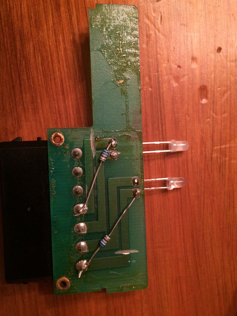 Ta da!!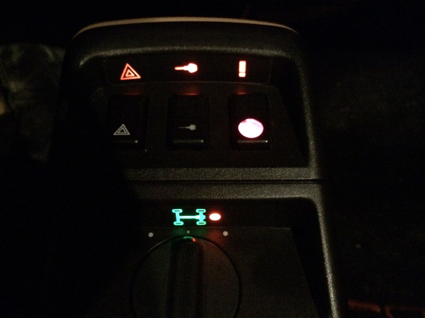