When you click on links to various merchants on this site and make a purchase, this can result in this site earning a commission. Affiliate programs and affiliations include, but are not limited to, the eBay Partner Network.
It was really quite easy to do and makes a big improvement.
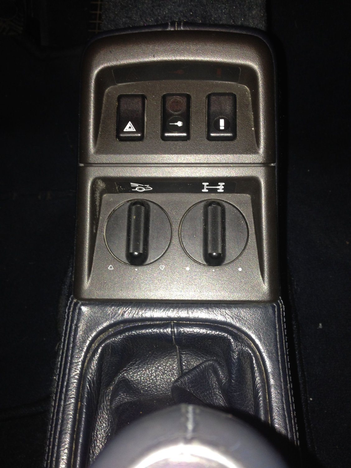
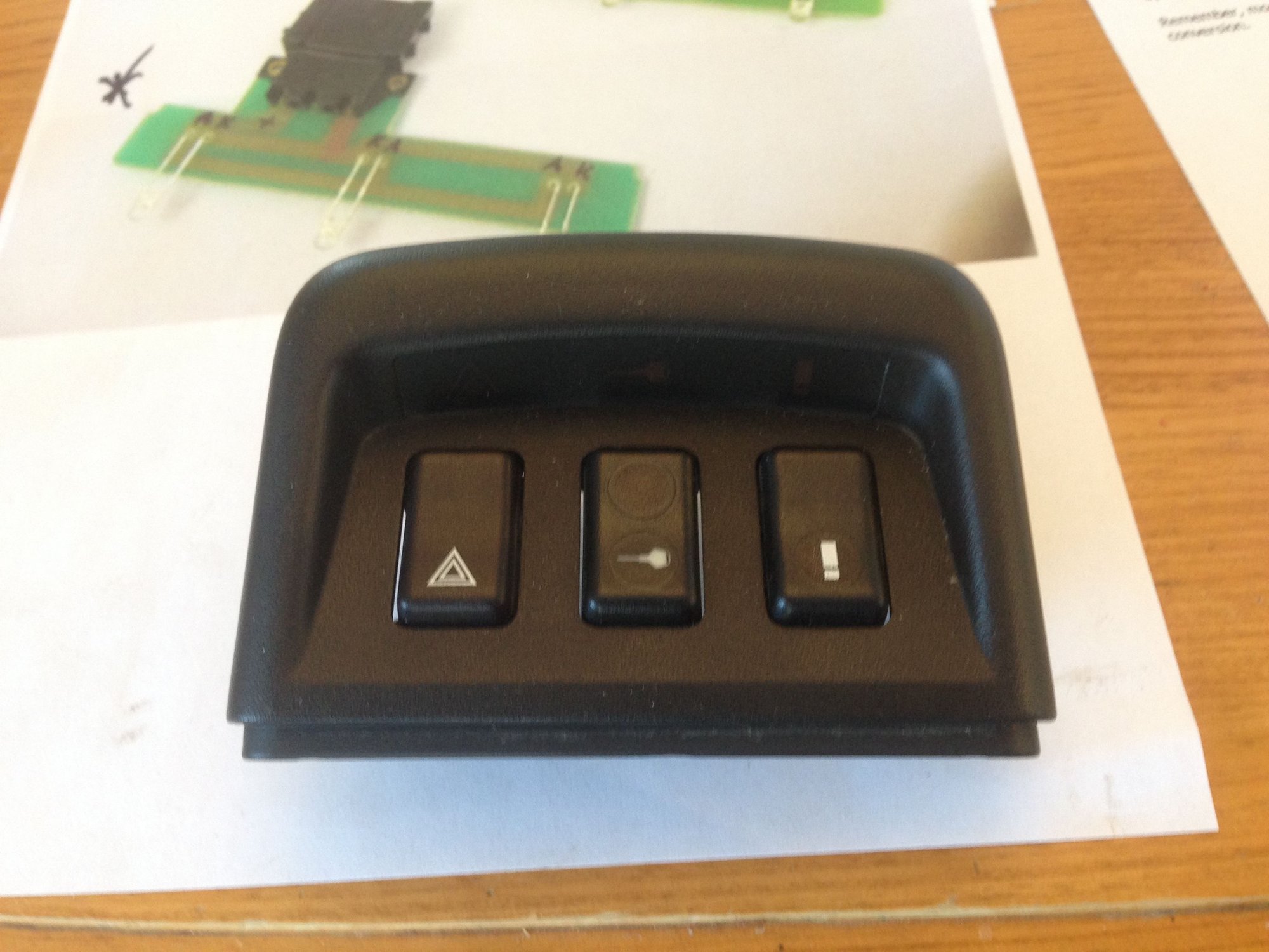
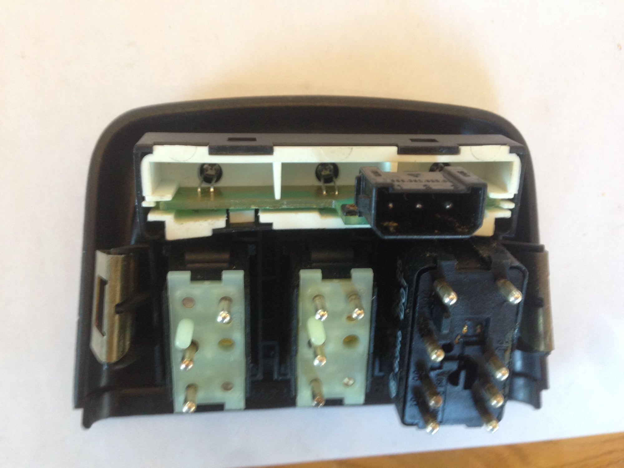
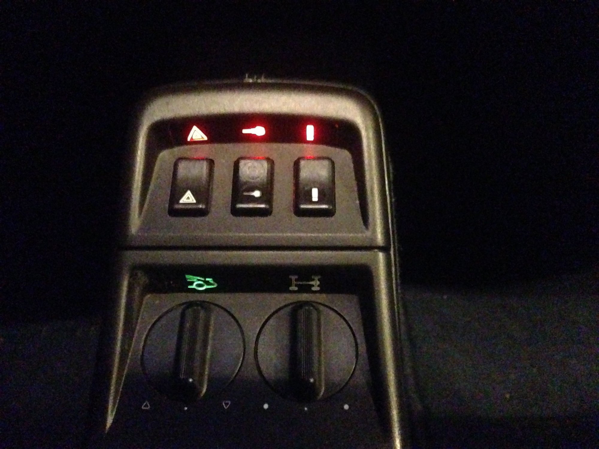
Mine just needed the red backlighted symbol bulbs above the top three switches replaced. Only one of the three occasionally lit up, but, it was mostly lights out as shown in the picture below.
No lights on above top three switches
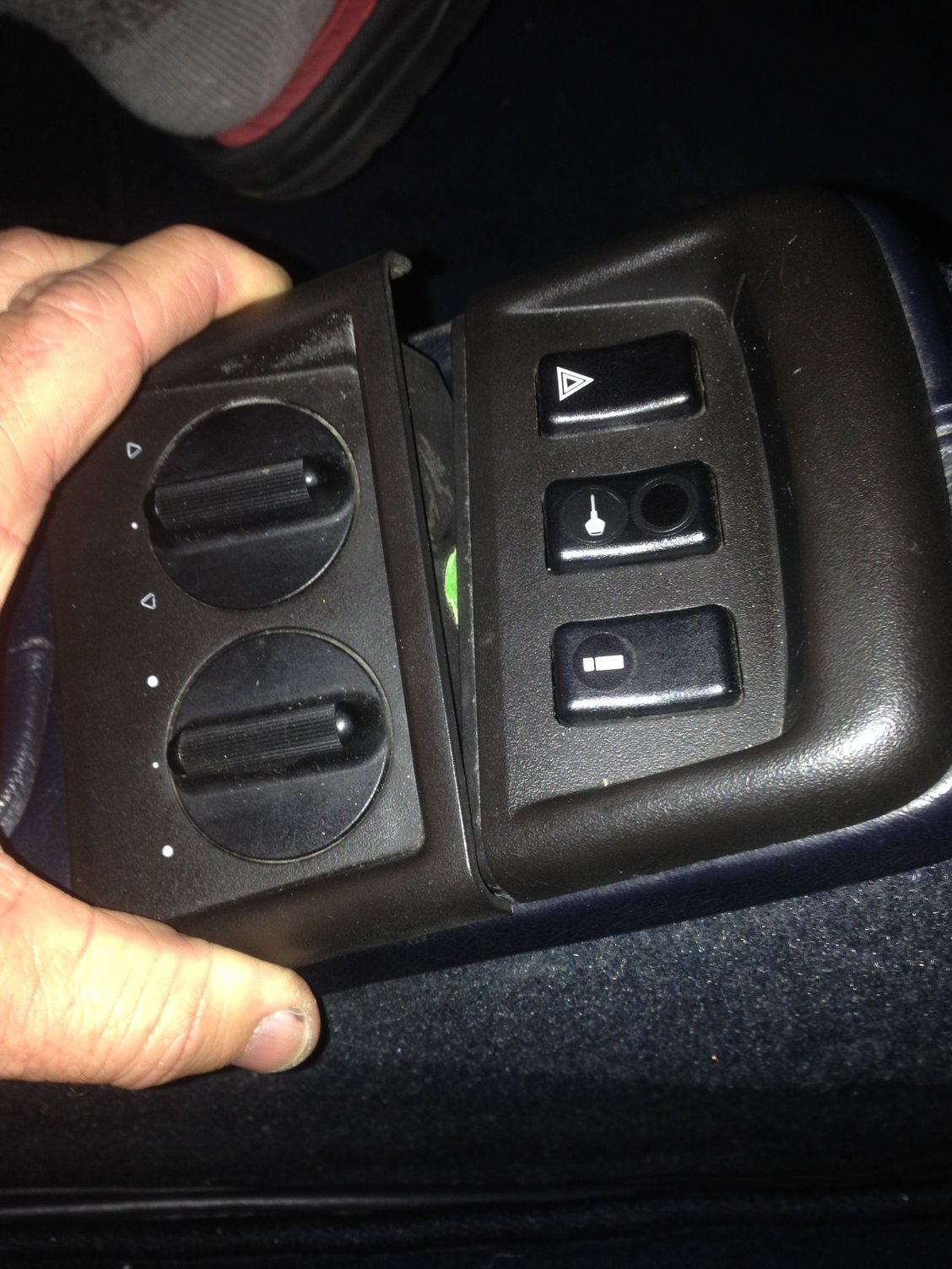
Remove the bottom console cover first by pulling gently on the sides. Once one side is loose it comes out easy.
You don't have to disconnect anything from the bottom cover. Just move it slightly out of the way so that the top cover can be pulled out.
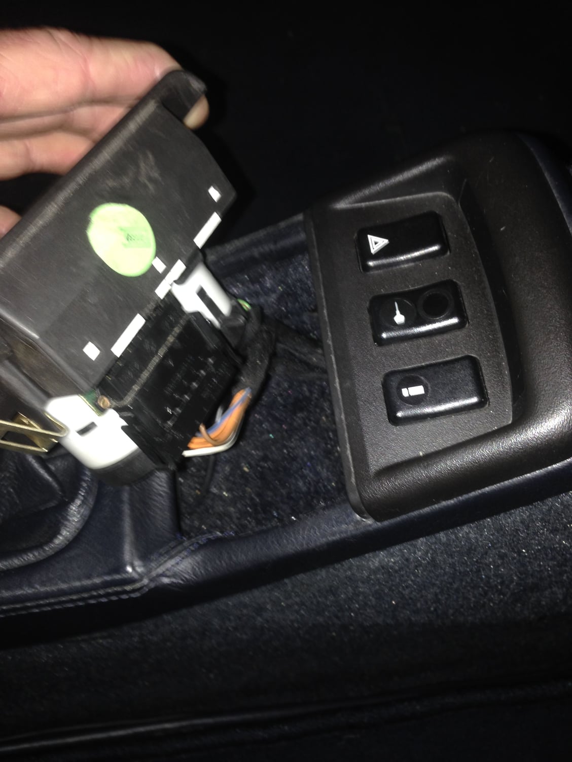
Pull the top cover up on one side. Again once the one side is out it's easy to remove.
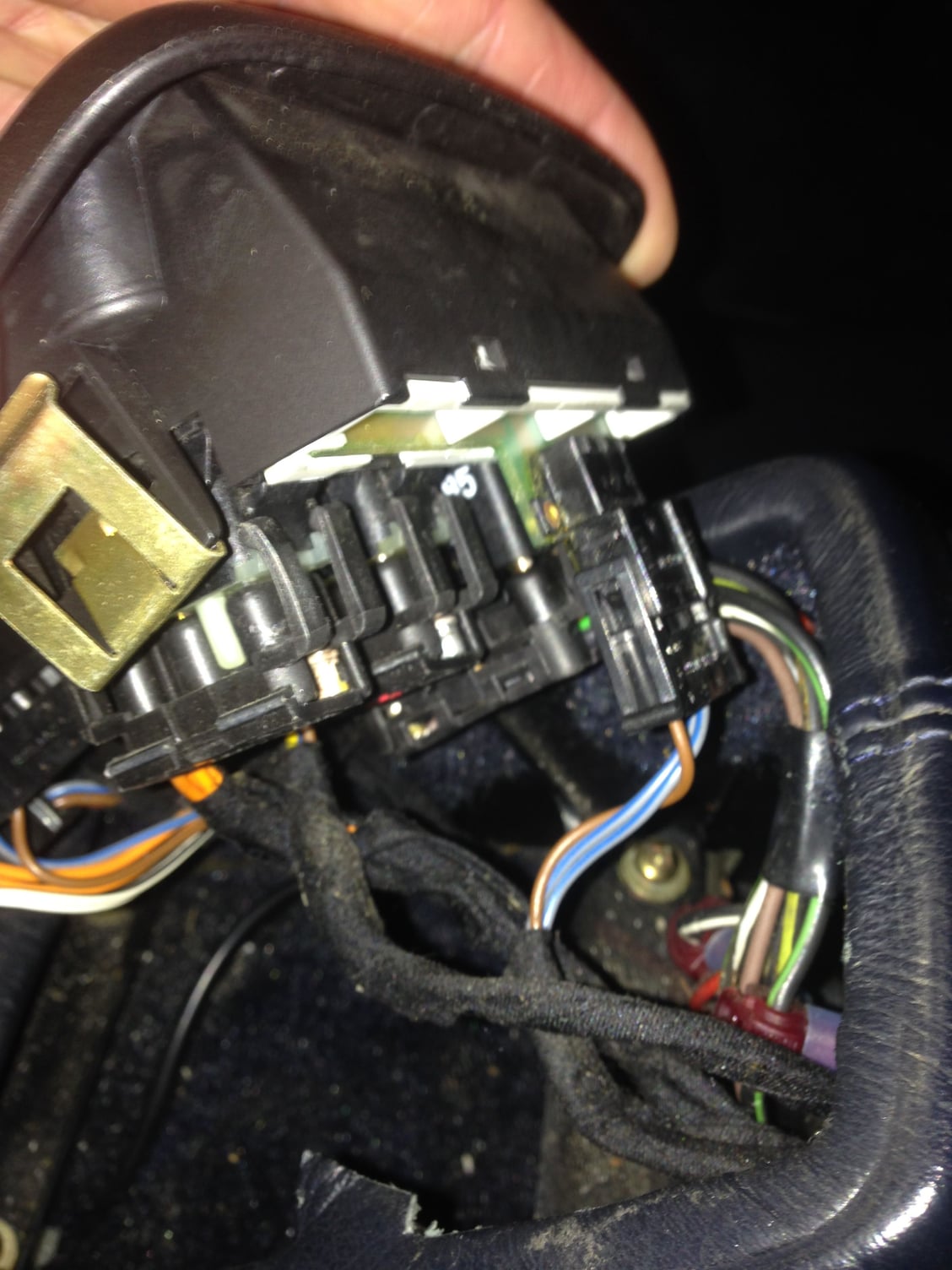
There's three wiring harness's for the switches to remove and one harness for the top symbol lights circuit board.
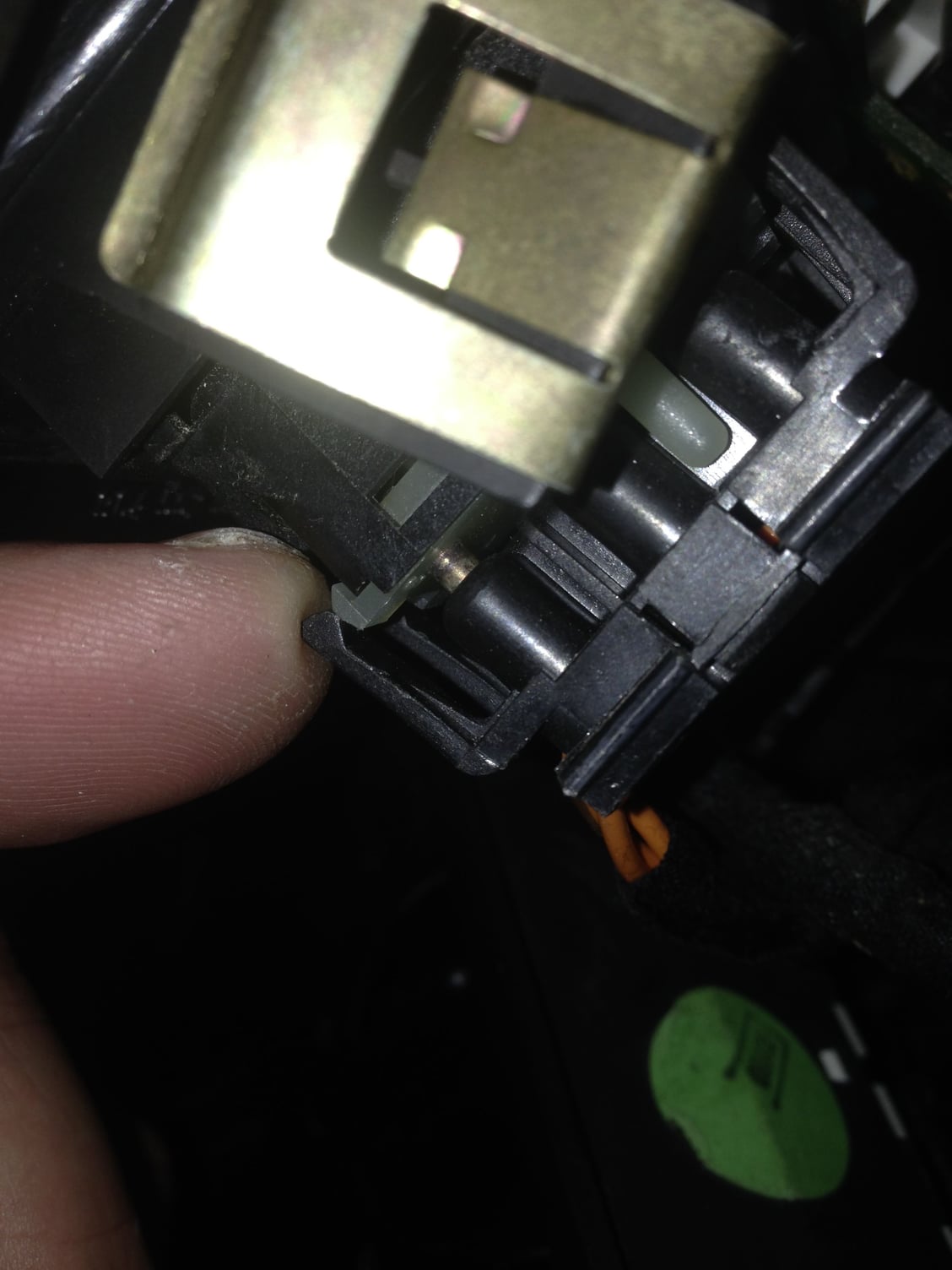
Unclip the two clips on the top and bottom of each harness before pulling them out. I used my finger and a small flat screwdriver.
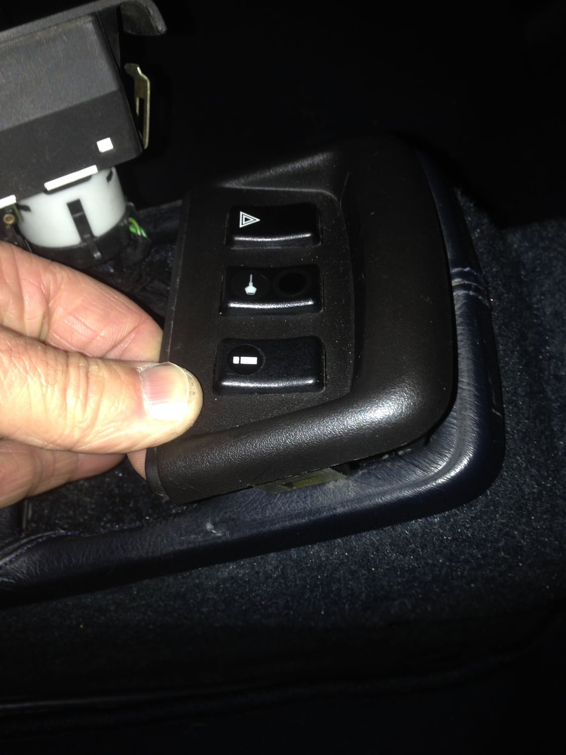
Top console cover removed.
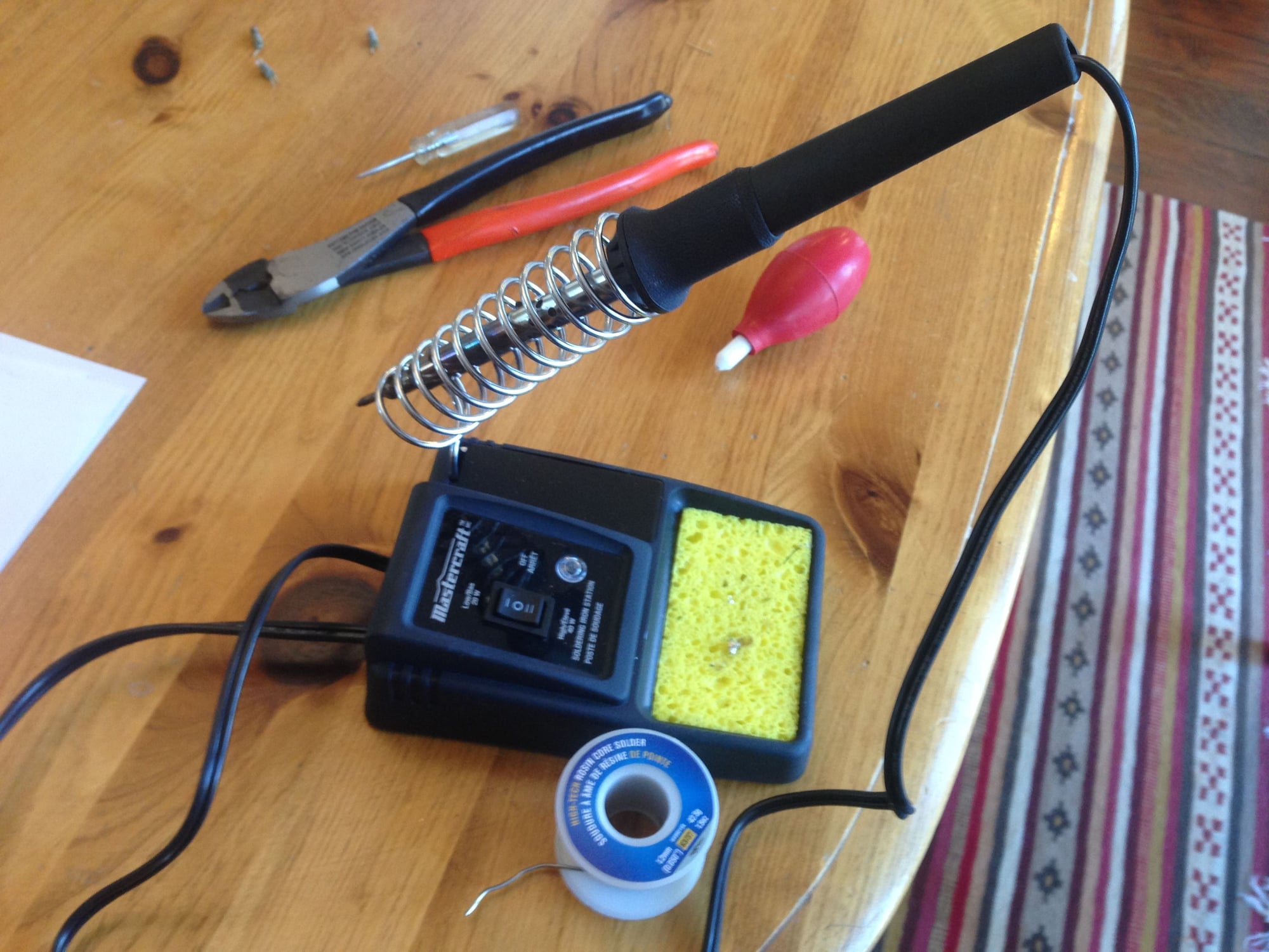
Bring out your small solder tool kit.
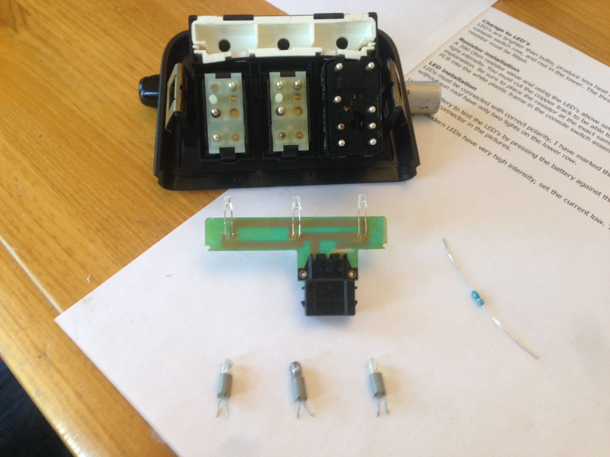
Once you unclip the circuit board and remove it, use the solder tool to heat up the solder holding the old bulbs in place, remove them and replace with LED lights (see Tore Bergvill website http://www.bergvillfx.com/consolerepair.html for details on resister placement and correct LED polarity)
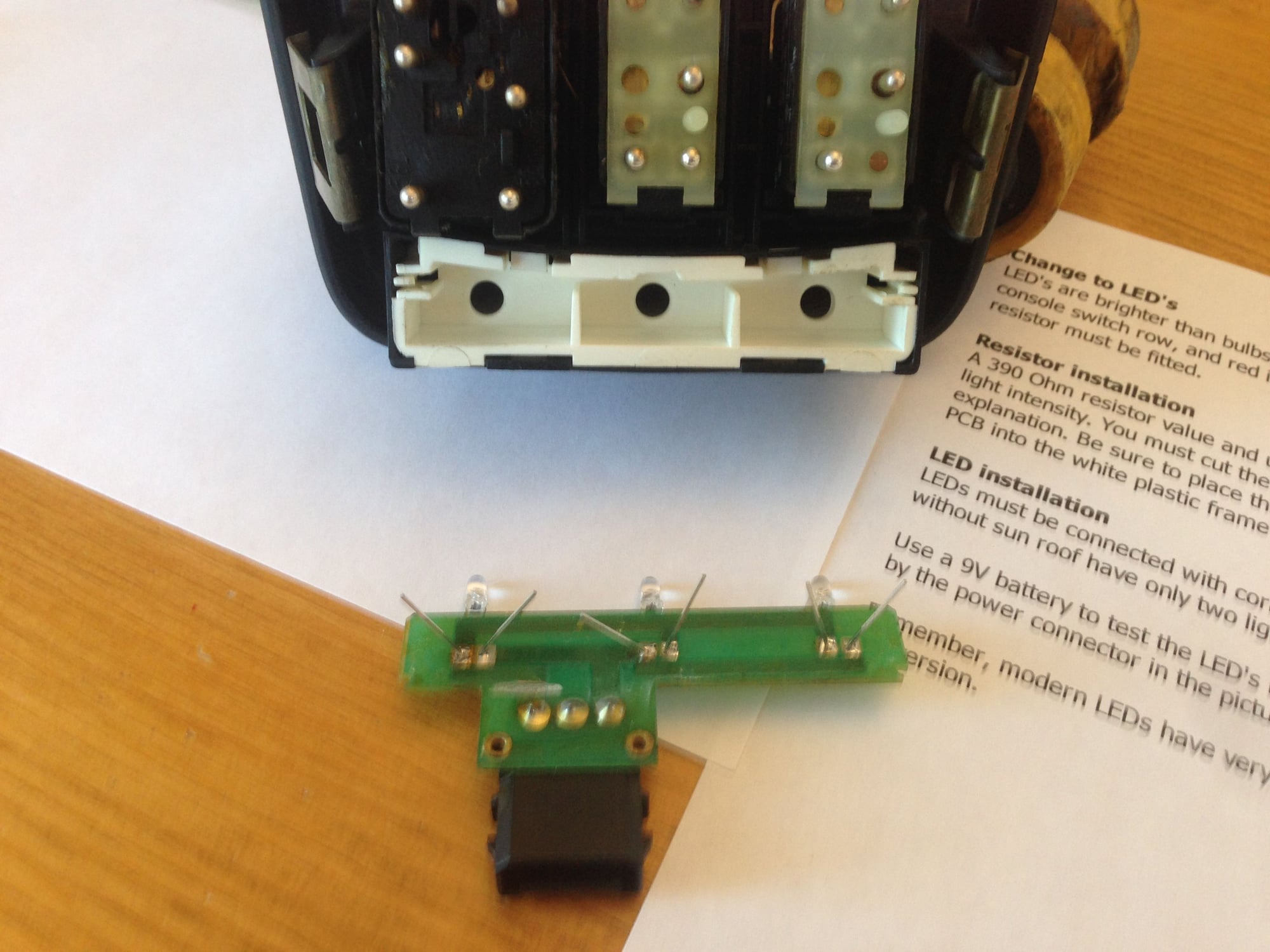
Bend LED cathod pins so that the LED bulbs will be in the same location as the old bulb use to be in.
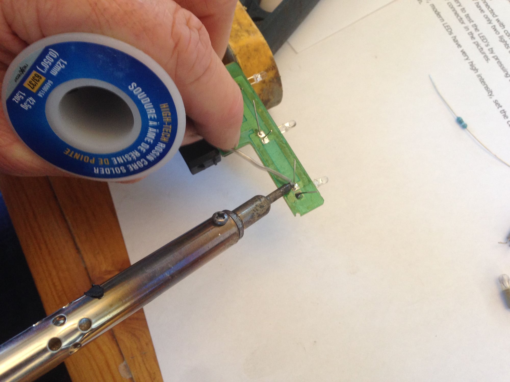
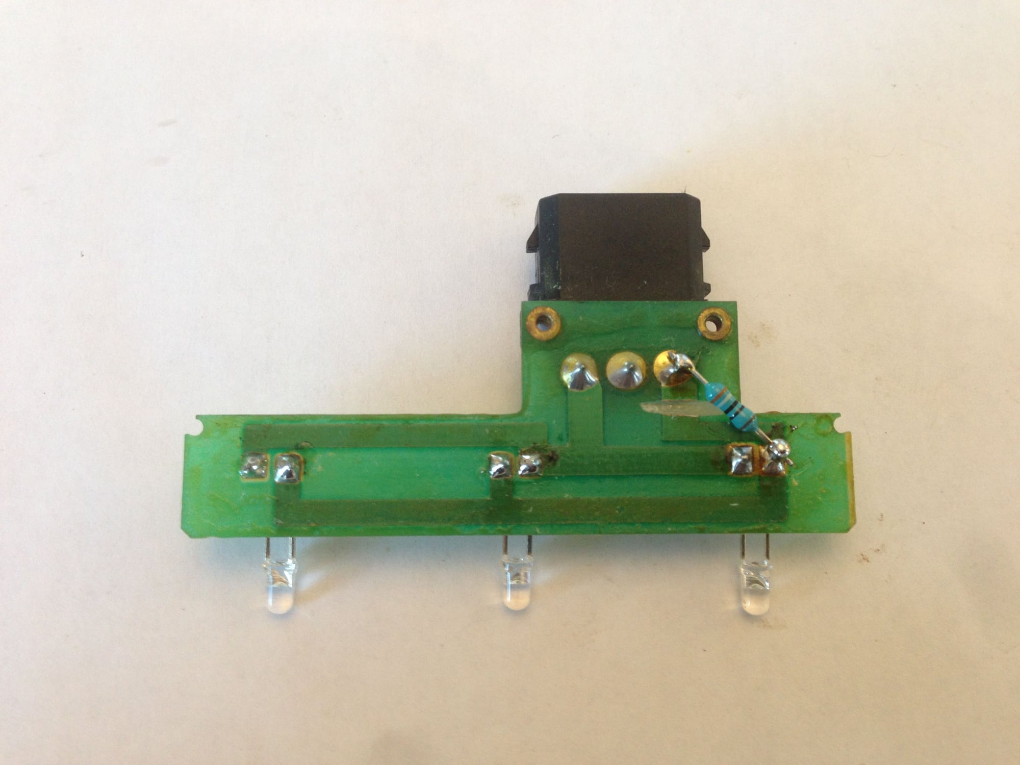
Solder LED cathode pins in place.
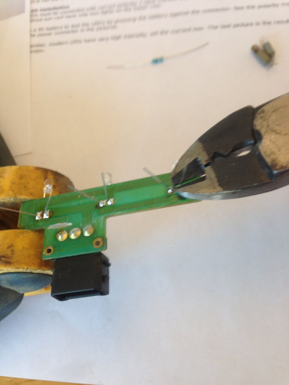
Snip pins as close to solder joint as possible.
Soldering of LED's complete. Also note where I cut the copper track on the circuit board just under the 390 Ohm resistor. This cut has to be made prior to soldering the resistor in place.
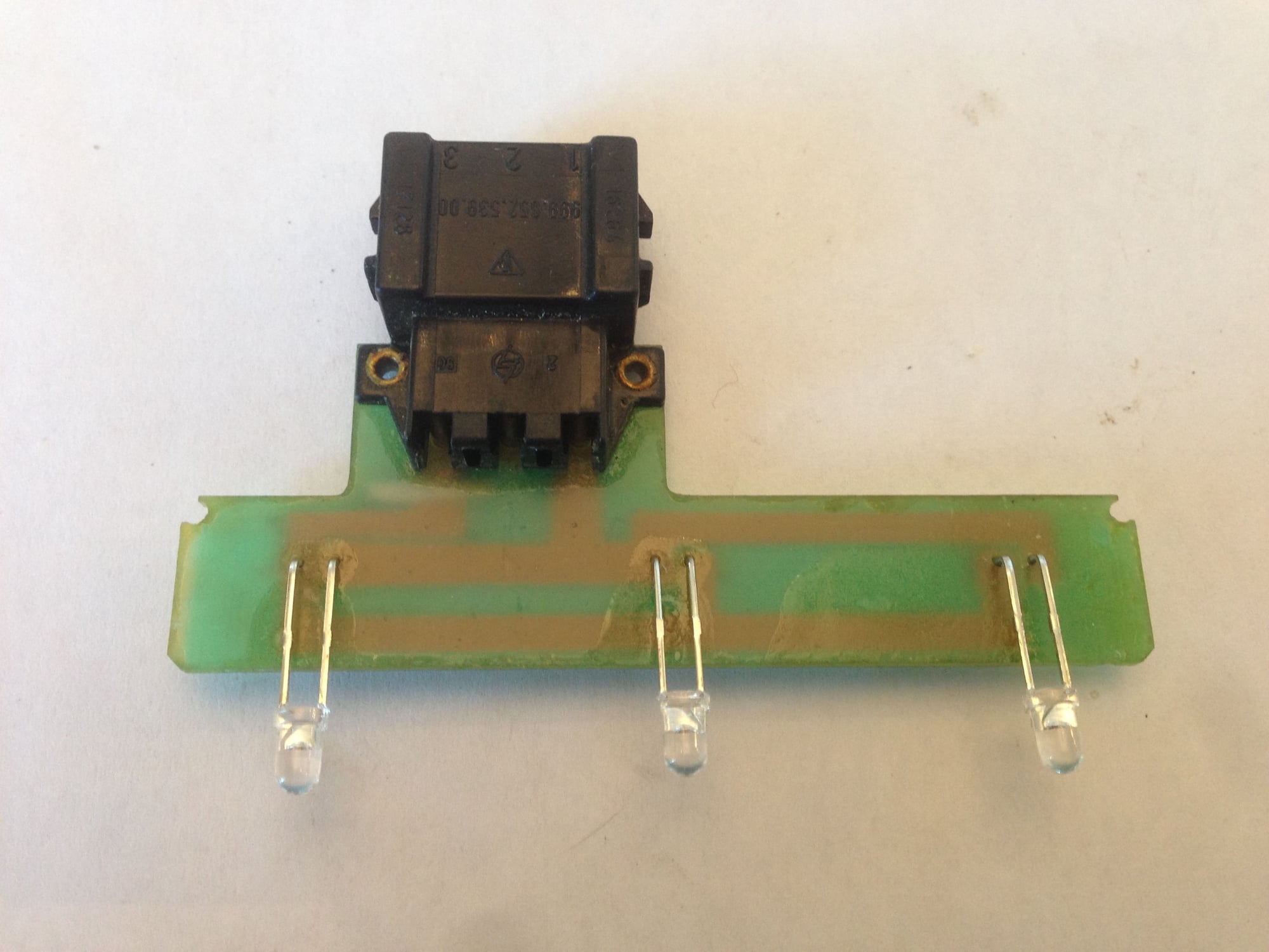
Then you can bend the LED wires slightly to ensure that they will line up with the holes in the white plastic harness in the console cover.
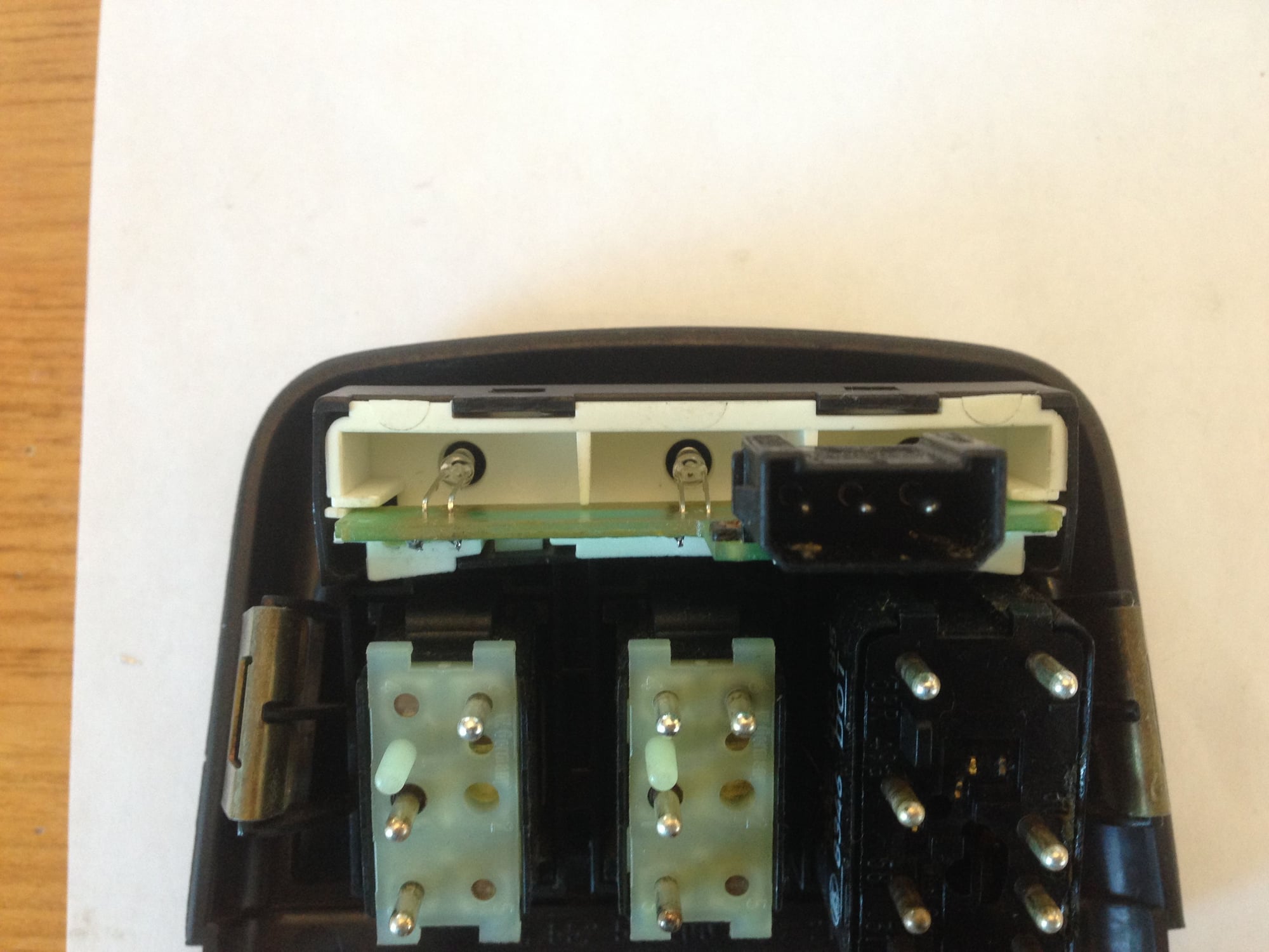
Slide the circuit board back in slowly making sure the LED lights line up with the holes.
This is what it looks like once it's all the way in and the white tabs on each end have clicked into place.
Then re-install the console cover (reverse of removal process) and check out those bright lights. They produce less heat and will last much longer than the originals.
A well tried and tested modification. I did mine about 8 yrs ago. If you use 12v LEDs, this removes the need for the resistor. I used 12v Red LEDs (5mm) which retain the warm red colour through the filter.
vagluv, I have thought of producing the PCB's, but have had problems finding the needed connectors. As far as I know are these not off-the-shelf types.
Cheers,
Tore
vagluv, I have thought of producing the PCB's, but have had problems finding the needed connectors. As far as I know are these not off-the-shelf types.
Cheers,
Tore
Please let us non-solderers know if you come up with anything
I just recently bought my soldering kit and it really is quite easy to do. Just make sure you get the thin 1.2mm soldering wire. It's much easier to work with. I also took apart an old car radio I pick-up from the second hand store and used the circuit boards to practice on.
I just recently bought my soldering kit and it really is quite easy to do. Just make sure you get the thin 1.2mm soldering wire. It's much easier to work with. I also took apart an old car radio I pick-up from the second hand store and used the circuit boards to practice on.
A well tried and tested modification. I did mine about 8 yrs ago. If you use 12v LEDs, this removes the need for the resistor. I used 12v Red LEDs (5mm) which retain the warm red colour through the filter.
Just completed this DIY using Tores kit. His kit was $12 shipped from Norway and I was quoted shipping for $12 from a Toronto store 3 hrs away and LEDs at $2 each!! Thanks Tore.
Only comment is I needed to use a Dremel wheel to trim down the wire protrusion as the side cutters I had didn't cut close enough.

 11-17-2014, 02:47 AM