

A 86.5 Intake Refresh Picture Thread from a first-timer

Thread Starter
Burning Brakes
Joined: Jul 2007
Posts: 946
Likes: 5
From: Columbia, MO / San Luis Obispo, CA
Hi everyone,
After years of warm A/C, Dwayne's instructions helped me replace three HVAC diaphragms (comb, footwell, and defrost) and clean out the pounds and pounds of leaves from my evaporator. And Alan Moore, Wally Plumley, and others on the board have helped me clean up my electrical system (ground points, shorts, low voltage, etc.)
Emboldened by these experiences, and encouraged by Roger Tyson, I decided to delve into refreshing the pipe organ of my 86.5. I started this thread as a guide for other first-timers of this procedure. I followed Mike Frye's instructions on this procedure. They are clearly written and very easy to understand. Thank you Mike as well.
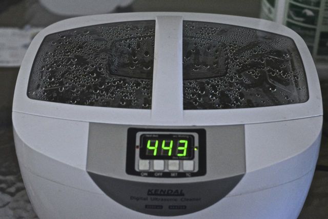
I purchased a couple of gadgets to help out. One was this ultrasonic cleaner that I got from Amazon. I filled it every "session" with 3 parts distilled to 1 part Simple Green. It did an amazing job of cleaning the grime off of parts.
130824 Ultrasonic.jpg
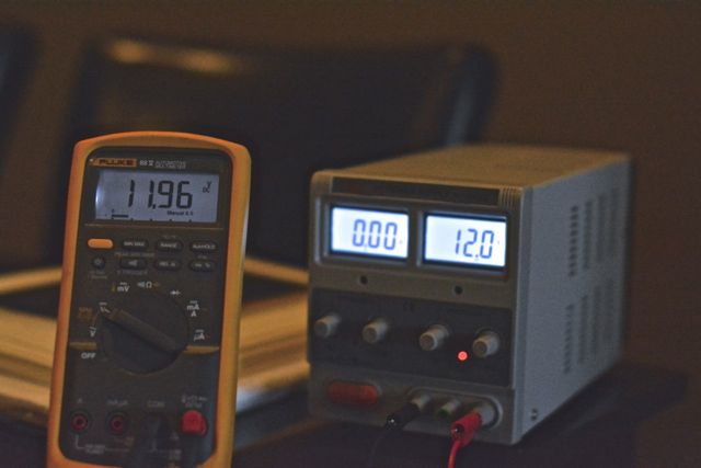
I also got the Caswell Copy Cad kit. It simulates cadmium plating of metals. With the kit I had to purchase a rectifier (also from Amazon.)
130823 Voltage Rectifier.jpg
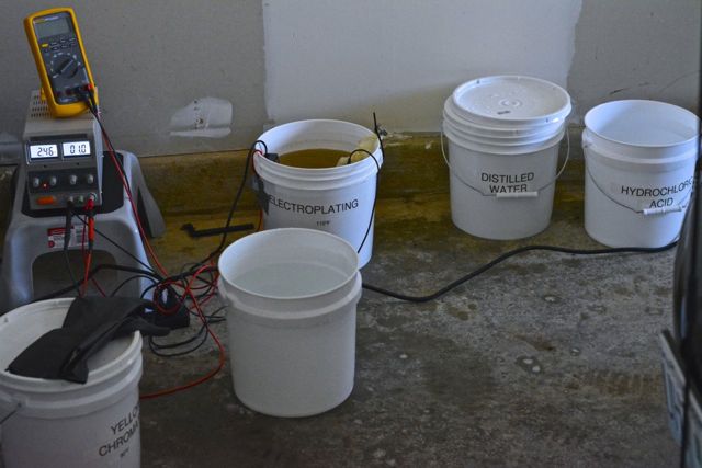
Also had to buy a few buckets, hydrochloric acid, yellow chromate solution (from Caswell), and a water heater (from Caswell.) All in all I spent around $400 for the kit.
130824 Caswell.jpg
With the Copy Cad, the thing that you will read all over the internet- and that I experienced first-hand, is that if the parts are not clean enough to be painted, the plating won't look good. If there is any grease on them, there will be a huge oil-slick looking blemish on your job.
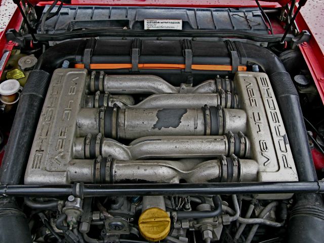
My engine compartment started off looking like this:
080222 Engine 1.jpg
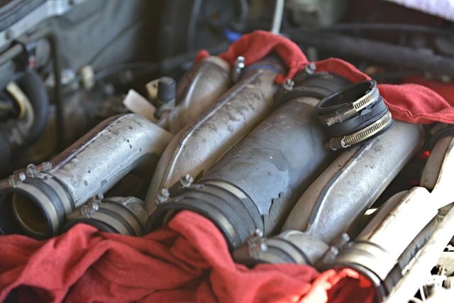
With the help of Mike's tutorial, I began to remove the intake runners and associated boots.
130811 Intake Pipes.jpg
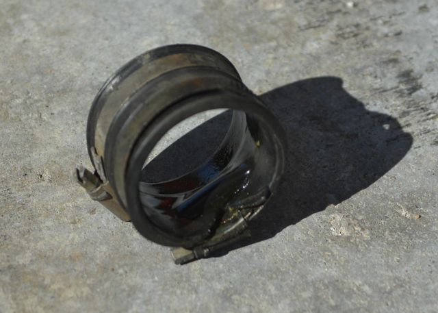
I was wondering why there was dried oil all over my cam covers- I think this might have had something to do with it:
130811 Ripped Intake Boot.jpg
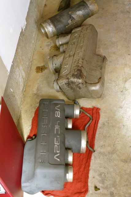
The paint on my intake runners and side boxes was so old that it was really easy to chip it off (which I did compulsively for about fifteen minutes before having to stop myself.) They'll all go to the powdercoater, along with the water bridge, the oil filler neck, the cross bar, and the two door lock surrounds that I will remove later.
130814 Intake Pieces.jpg
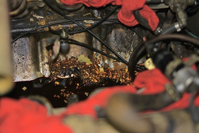
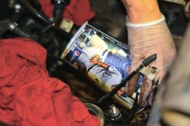
Once the intake was out and the throttle body was out, I was greeted by the most filthy valley- more filthy than any picture that I found on Rennlist. It had a rat's nest in there, and many little brown pods that were either seeds or something much more disgusting.
130814 Valley 1.jpg
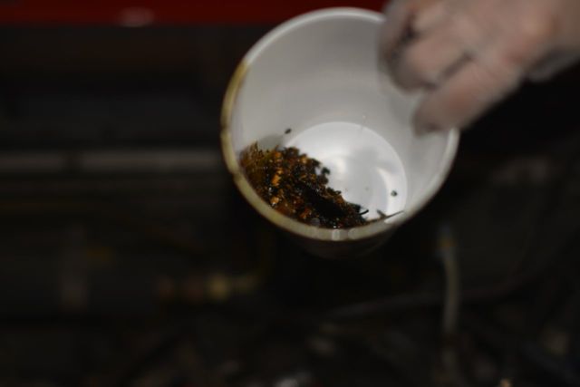
Instead of using a towel I ended up scooping the mess up with a cup I got at a baseball game.
130814 Scoop.jpg
130814 Crud.jpg
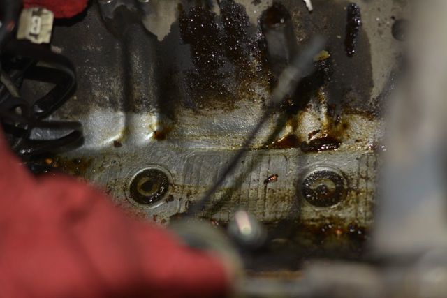
After a lot of scoops, it got a bit better.
130814 Valley 5.jpg
I fashioned intake port covers from cardboard, but they are a little flimsy, and I am deathly afraid of getting any dirt into the intake. I won't clean the valley any further until I receive the intake port covers I ordered from 928 Specialists. If you are a newbie like me, I highly recommend buying these.
After years of warm A/C, Dwayne's instructions helped me replace three HVAC diaphragms (comb, footwell, and defrost) and clean out the pounds and pounds of leaves from my evaporator. And Alan Moore, Wally Plumley, and others on the board have helped me clean up my electrical system (ground points, shorts, low voltage, etc.)
Emboldened by these experiences, and encouraged by Roger Tyson, I decided to delve into refreshing the pipe organ of my 86.5. I started this thread as a guide for other first-timers of this procedure. I followed Mike Frye's instructions on this procedure. They are clearly written and very easy to understand. Thank you Mike as well.
I purchased a couple of gadgets to help out. One was this ultrasonic cleaner that I got from Amazon. I filled it every "session" with 3 parts distilled to 1 part Simple Green. It did an amazing job of cleaning the grime off of parts.
130824 Ultrasonic.jpg
I also got the Caswell Copy Cad kit. It simulates cadmium plating of metals. With the kit I had to purchase a rectifier (also from Amazon.)
130823 Voltage Rectifier.jpg
Also had to buy a few buckets, hydrochloric acid, yellow chromate solution (from Caswell), and a water heater (from Caswell.) All in all I spent around $400 for the kit.
130824 Caswell.jpg
With the Copy Cad, the thing that you will read all over the internet- and that I experienced first-hand, is that if the parts are not clean enough to be painted, the plating won't look good. If there is any grease on them, there will be a huge oil-slick looking blemish on your job.
My engine compartment started off looking like this:
080222 Engine 1.jpg
With the help of Mike's tutorial, I began to remove the intake runners and associated boots.
130811 Intake Pipes.jpg
I was wondering why there was dried oil all over my cam covers- I think this might have had something to do with it:
130811 Ripped Intake Boot.jpg
The paint on my intake runners and side boxes was so old that it was really easy to chip it off (which I did compulsively for about fifteen minutes before having to stop myself.) They'll all go to the powdercoater, along with the water bridge, the oil filler neck, the cross bar, and the two door lock surrounds that I will remove later.
130814 Intake Pieces.jpg
Once the intake was out and the throttle body was out, I was greeted by the most filthy valley- more filthy than any picture that I found on Rennlist. It had a rat's nest in there, and many little brown pods that were either seeds or something much more disgusting.
130814 Valley 1.jpg
Instead of using a towel I ended up scooping the mess up with a cup I got at a baseball game.
130814 Scoop.jpg
130814 Crud.jpg
After a lot of scoops, it got a bit better.
130814 Valley 5.jpg
I fashioned intake port covers from cardboard, but they are a little flimsy, and I am deathly afraid of getting any dirt into the intake. I won't clean the valley any further until I receive the intake port covers I ordered from 928 Specialists. If you are a newbie like me, I highly recommend buying these.
Last edited by syoo8; Jan 15, 2014 at 09:43 PM.
Thread Starter
Burning Brakes
Joined: Jul 2007
Posts: 946
Likes: 5
From: Columbia, MO / San Luis Obispo, CA
A couple of observations thus far:
- The passenger side CO tube (which apparently doesn't do anything) broke as I removed the PS (passenger side) intake box.
- As Mike Frye said correctly, the PS fuel rail has a very narrow counter-hold. I went to my local bike shop and the guy there loaned me his 17mm bike wrench for an hour.
- The injector plugs, for someone who has never done this, were difficult to remove. The way they work- if you are like me and have never detached one of these things- is that there is a paper-clip-like metal wire that goes around most of the perimeter of the clip, holding it in place. It needs to be pried loose to disconnect the clip. The way I ended up doing it was using a very very sharp micro-screwdriver to wedge between the clip and the connector, while at the same time having a magnet nearby to pick up the clip just in case it went flying off.
- The breather hoses from the side of the valve covers were so stiff on my car that I swore they were plastic coated metal. Only after a call from Roger Tyson did I have the courage to crack the once-rubber hoses and remove them.
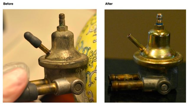
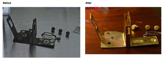
- I put every nut, washer, and bolt into a baggie and labeled everything. Then, one-by-one, I put the contents of each baggie into the ultrasonic cleaner, rinsed, wire-wheeled, and finally re-plated using the Caswell Copy Cad. The results look good to me. If you use the Copy Cad it is important to not disturb the parts for a few hours while they dry, otherwise the plating flakes off and you have to start over. Here are a couple of parts that I used Copy Cad on:
928.110.429.07.jpg
Test Port.jpg
- The passenger side CO tube (which apparently doesn't do anything) broke as I removed the PS (passenger side) intake box.
- As Mike Frye said correctly, the PS fuel rail has a very narrow counter-hold. I went to my local bike shop and the guy there loaned me his 17mm bike wrench for an hour.
- The injector plugs, for someone who has never done this, were difficult to remove. The way they work- if you are like me and have never detached one of these things- is that there is a paper-clip-like metal wire that goes around most of the perimeter of the clip, holding it in place. It needs to be pried loose to disconnect the clip. The way I ended up doing it was using a very very sharp micro-screwdriver to wedge between the clip and the connector, while at the same time having a magnet nearby to pick up the clip just in case it went flying off.
- The breather hoses from the side of the valve covers were so stiff on my car that I swore they were plastic coated metal. Only after a call from Roger Tyson did I have the courage to crack the once-rubber hoses and remove them.
- I put every nut, washer, and bolt into a baggie and labeled everything. Then, one-by-one, I put the contents of each baggie into the ultrasonic cleaner, rinsed, wire-wheeled, and finally re-plated using the Caswell Copy Cad. The results look good to me. If you use the Copy Cad it is important to not disturb the parts for a few hours while they dry, otherwise the plating flakes off and you have to start over. Here are a couple of parts that I used Copy Cad on:
928.110.429.07.jpg
Test Port.jpg
Thread Starter
Burning Brakes
Joined: Jul 2007
Posts: 946
Likes: 5
From: Columbia, MO / San Luis Obispo, CA
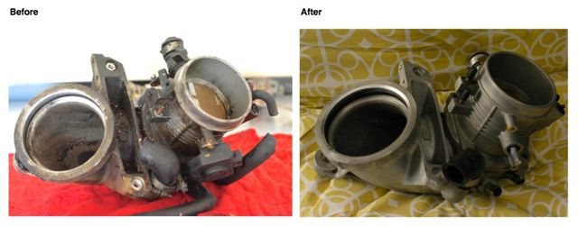
Next, the throttle body and 'air guide' (I think that is what it is called.) They too were covered in oil, mouse hair, and bits of unidentified organic material. To clean it, I simply removed the throttle position sensor (since I was receiving a new one from Roger) and dunked the unit into the ultrasonic cleaner, plugging all of the vacuum holes with plugs (that I bought at Amazon as well.)
Throttle Body.jpg
I took pictures-many pictures- of the throttle body, specifically the throttle position sensor, so that I could put the new TPS on in exactly the same location.
130817 Throttle Position Switch.jpg
QUESTION: Do people put any lubrication in any part of the throttle body?
Throttle Body.jpg
I took pictures-many pictures- of the throttle body, specifically the throttle position sensor, so that I could put the new TPS on in exactly the same location.
130817 Throttle Position Switch.jpg
QUESTION: Do people put any lubrication in any part of the throttle body?
Craic Head
Lifetime Rennlist
Member
Lifetime Rennlist
Member

Joined: Sep 2006
Posts: 8,795
Likes: 7
From: Jersey Shore, USA
Hey Scott,
Great start! That copy cad looks pretty cool.
I'm glad the write-up is helping.
The only thing I used lube on for the throttle body was for the replacement O-rings in the sides where I replaced the old, hard plastic parts that were in there. The stuff I used is called syl-glide I think and It's just like petroleum jelly in consistency. It was just so I didn't have to put the butterfly pivot rod into the new O-rings dry. Other than that, it will lube itself over time.
Thread Starter
Burning Brakes
Joined: Jul 2007
Posts: 946
Likes: 5
From: Columbia, MO / San Luis Obispo, CA
Mike,
You are a mensch (!) for writing that terrific write-up. It is fantastic.
Should I take the throttle body apart? I have read on Rennlist that it is a pain-in-the-*ss to put back together.
You are a mensch (!) for writing that terrific write-up. It is fantastic.
Should I take the throttle body apart? I have read on Rennlist that it is a pain-in-the-*ss to put back together.
Trending Topics
Craic Head
Lifetime Rennlist
Member
Lifetime Rennlist
Member
Joined: Sep 2006
Posts: 8,795
Likes: 7
From: Jersey Shore, USA
Just take a few pics of the spring assembly so you know how it goes back together and plan to do it in one sitting. Take it apart and lay the parts out on a work surface in the order they came out, then clean it all up and replace the O-rings and assembly is.... well you know.
IMO, if you haven't done it, it needs it. It probably should be added to the write-up for the intake refresh since one of the goals of that is to have no old plastic or rubber bits in the top end of the engine that are known wear items.
Here is my thread on testing/rebuilding it, in case you're interested.
This is the jig I built to test it for leaks:
Good luck!
Rennlist Member
Joined: Nov 2009
Posts: 8,659
Likes: 424
From: Dubuque, IA
A couple of observations thus far:
- The passenger side CO tube (which apparently doesn't do anything) broke as I removed the PS (passenger side) intake box.
- As Mike Frye said correctly, the PS fuel rail has a very narrow counter-hold. I went to my local bike shop and the guy there loaned me his 17mm bike wrench for an hour.
- The injector plugs, for someone who has never done this, were difficult to remove. The way they work- if you are like me and have never detached one of these things- is that there is a paper-clip-like metal wire that goes around most of the perimeter of the clip, holding it in place. It needs to be pried loose to disconnect the clip. The way I ended up doing it was using a very very sharp micro-screwdriver to wedge between the clip and the connector, while at the same time having a magnet nearby to pick up the clip when goes flying off.
. . . snip
Drifting
Joined: Jun 2006
Posts: 2,708
Likes: 77
From: Indianapolis Area
Wow, great job! I recall being in your exact same shoes a few years back, embarking on my first (and only) intake refresh project. Everything from a very dirty valley, to bagging and tagging, to cleaning and taking a wire wheel to every part. I especially like you mini plating plant!
Keep us posted on you project.
Keep us posted on you project.

Racer
Joined: Mar 2013
Posts: 304
Likes: 0
From: San Diego, CA
*shudders at the icky "seed" picture*
I think I rather work an extra couple of weeks and send my car to Gregg for an intake refresh, that and I want to have him do the oil consumption upgrades (well at least for my first intake refresh)
But I am interested in how your refresh progresses good luck with your 100% DIY refresh.
I think I rather work an extra couple of weeks and send my car to Gregg for an intake refresh, that and I want to have him do the oil consumption upgrades (well at least for my first intake refresh)
But I am interested in how your refresh progresses good luck with your 100% DIY refresh.
Last edited by eijun; Aug 29, 2013 at 02:39 PM.
Thread Starter
Burning Brakes
Joined: Jul 2007
Posts: 946
Likes: 5
From: Columbia, MO / San Luis Obispo, CA
Mike, Eijun, Kirt, Jeff, everyone: thank you for your kind words of encouragement. This has been a really fun project for me.
Eijun, I agree, sending the car to God, er- Greg Brown, would yield the most effective results. He won't make mistakes, whereas I am making mistakes almost every step of the way. He'll do it in 15 hours, whereas I am doing it an hour a day and I've already spent nearly a month. And I'm not even close to being done.
However, I embarked on this project to learn about how the car works. It is amazing to me how once one takes something apart, one really gets a better sense of what they do.
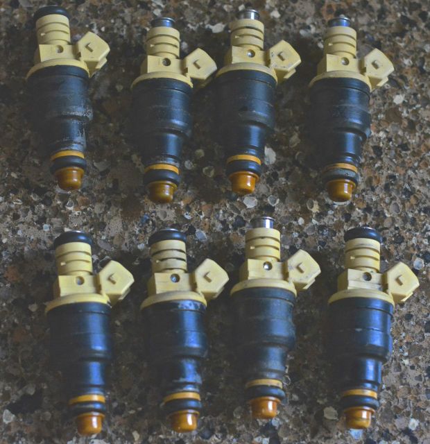
For example, the fuel rails. I've seen the fuel rail covers on my S4, and knew that the fuel rails delivered fuel to the injectors conceptually, but actually holding- and cleaning- both fuel rails makes me digest the information that much better. Same goes for the injectors. I heard of a "pintle cap" but never touched one, nor saw a broken one until I removed (with great effort- it was surprising how much force I needed to pull out the injectors.)
The cracked pintle cap is on the lower right injector.
130827 Injectors.jpg
Eijun, I agree, sending the car to God, er- Greg Brown, would yield the most effective results. He won't make mistakes, whereas I am making mistakes almost every step of the way. He'll do it in 15 hours, whereas I am doing it an hour a day and I've already spent nearly a month. And I'm not even close to being done.
However, I embarked on this project to learn about how the car works. It is amazing to me how once one takes something apart, one really gets a better sense of what they do.
For example, the fuel rails. I've seen the fuel rail covers on my S4, and knew that the fuel rails delivered fuel to the injectors conceptually, but actually holding- and cleaning- both fuel rails makes me digest the information that much better. Same goes for the injectors. I heard of a "pintle cap" but never touched one, nor saw a broken one until I removed (with great effort- it was surprising how much force I needed to pull out the injectors.)
The cracked pintle cap is on the lower right injector.
130827 Injectors.jpg
Thread Starter
Burning Brakes
Joined: Jul 2007
Posts: 946
Likes: 5
From: Columbia, MO / San Luis Obispo, CA
Hi Mike,
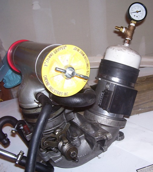
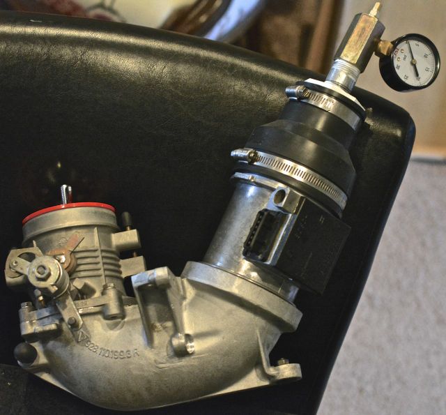
Following your procedure, I went to Home Depot and bought some plumbing to fashion a "leak detector."
130829 TB Apparatus.jpg
The frustrating thing is that the MAF would fly apart from the air guide whenever I'd pressurize the little gadget. Did you have this issue?
I see that in your picture you attached the throttle body to the famous "T", which I didn't do. (My "T" is flaking paint and has oil in it, and all in all, is disgusting�
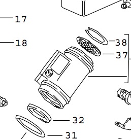
By the way, in my car (and in the picture of your car's MAF) we seem to be mounting the MAF upside-down compared to the PET diagram.
Screen Shot 2013-08-29 at August 29, 2013 2.10.13 PM .jpg
I am assuming that PET in this case is incorrect?
Following your procedure, I went to Home Depot and bought some plumbing to fashion a "leak detector."
130829 TB Apparatus.jpg
The frustrating thing is that the MAF would fly apart from the air guide whenever I'd pressurize the little gadget. Did you have this issue?
I see that in your picture you attached the throttle body to the famous "T", which I didn't do. (My "T" is flaking paint and has oil in it, and all in all, is disgusting�
By the way, in my car (and in the picture of your car's MAF) we seem to be mounting the MAF upside-down compared to the PET diagram.
Screen Shot 2013-08-29 at August 29, 2013 2.10.13 PM .jpg
I am assuming that PET in this case is incorrect?
Rennlist Member
Joined: Nov 2009
Posts: 8,659
Likes: 424
From: Dubuque, IA
You have to get the clamps pretty tight. If you rebuild it with all new bearings and seals you'll have a sufficiently tight intake. I built a tester as well and used it once. Still was fun to do.
Craic Head
Lifetime Rennlist
Member
Lifetime Rennlist
Member
Joined: Sep 2006
Posts: 8,795
Likes: 7
From: Jersey Shore, USA
Scott,
You're right, the MAF will have to be somehow strapped or bungeed on there for the test, but if it's blowing off, it's got to be a pretty good test. Mine was blowing out through those old cracked o-rings at very low pressure. You shouldn't need more than a couple of psi to test it.
(also, as an FYI you might want to turn off your compressor before putting the hose on your shrader valve because when you're listening for leaks it doesn't help to have your compressor kick on).
For the MAF, I don't know about the orientation. I just always put it back on the way I took it off. I don't know if you can get to the adjustment screw if it was at the bottom when everything was assembled again, could you?