When you click on links to various merchants on this site and make a purchase, this can result in this site earning a commission. Affiliate programs and affiliations include, but are not limited to, the eBay Partner Network.
I believe that the dyno, 1D simulation software, and flow bench all complement each others. By using all three, one will get a lot more return on R&D $'s and hours than using only one or two.
(With 3D simulation software, flow bench becomes obsolete. Today's car factories, even top racing program facilities, no longer have flow benches at all. They are trying to do away with wind tunnels as well. But this software that I have is 1D, so it needs to be combined with flow bench data. In other words, I am stuck in the 1980's, both in terms of my car of choice and the technology that I am using!)
While theory and simulations are fun, one needs to be careful to not turn those into fact....which seems like what is happening, in this thread. Actual real life dyno testing trumps theory and any simulation one can find. And I've done that testing....over and over again. So, for those of you that haven't been following what I've been doing for the past 10 years....or just got out of a cave in the mountains..... A hand ported and 2R manifold (which only addresses the bellmouths and as far as one can reach into the ports with an 8" carbine cutter), with stock exhaust and cats will "support" 340 rwhp (in a 928 with an automatic) on a 6.5 liter stroker. (That's right around 400hp flywheel HP.) Absolutely nothing that I did for 6 months of solid research and development made any change.....the dyno printouts were virtually exactly the same....to the point of being absurd. Cam timing changes, changing camshafts, changing intake plenum spacers, larger butterfly, dramtically altering the lower plenum, changing the injectors, tuning for days and days on end made any difference. The only change that did anything at all was a 10 rwhp loss when I installed a smaller resonator exhaust system, from the cats back. When we finally bolted on my highly researched and developed headers and exhaust system (with cats), we were able to "move" the power up to the 360hp (rwhp) range....but repeating all of the earlier tests, the engine was absolutely "stuck" at that power output. I believe two things limited that engine...and the testing was planned, until the car had a terminal incident. I believe the driveshaft and possibly the torque convertor had reached the limit of what they could transmit. There was also a possibility that a change to the 4R manifold would have helped. I have bolted on my prototype custom manifold onto a well tuned GT....and the results were pretty spectacular...but I doubt that an intake change on a stock 5.0 engine is going to do very much. I will find out, because I test....and test....and test. Real world, no theory, no "dyno cheating" glory testing.
Are you saying that your testing and R&D do not include any theoretical calculations?
I find this difficult to believe if that's the correct interpretation of your post.
In addition, it seems highly doubtful that the global engineering community would adopt highly complex software engineering tools such as Solidworks and use them to design complete engines that can be CAD tested based on all those physics theories and CFD theories around thermodynamics and heat management incorporated into the software. Not to mention material science theories of using dissimilar materials in the engine and having the software analyze the effects.
Granted, testing will validate a predetermined or accidental outcome. However, without the theory, there can be no expected or unexpected outcome.. Both theories and validation testing are needed in product development.
If your statement is correct, then it would mean that the simple scientific theory of the Otto cycle as isentropic and isochoric processes would be irrelevant, and the patent suit on four stroke engines among Otto/Deutz, de Rochas, Daimler and Maybach would also be irrelevant... No?
Can you expand on that? I am not sure I understand what you are saying....
Greg can elaborate on what he meant, but this may be related. What we've found is that the unmodified S4 automatic transmission does eat a lot of power at 5000 rpm and above. I don't know why that is, but running a twin turbo system in a manual car and a automatic transmission car, back to back, will result in meaningfully less power in the rear axle for the automatic car above 5000 rpm. I am still learning engines, transmissions remain a complete mystery to me beyond that observation.
Coming back to the accuracy of the 1D simulations: I believe that a flow bench data and this simulation system does a very good job predicting the impact of changes on the intake side. I get to test more of that when Hans gets those flanges ready, the plan is to mock up a simple test manifold and see if the results correlate with predictions.
Where the simulations have the hardest time matching reality is on the exhaust side. The exhaust flow near the port is very difficult to model, and the 1D models are usually not very accurate in predicting what small changes to exhaust do to the torque curve. Optimized headers will still have to be developed mostly on a dyno, if all that one has in terms of software is 1D simulation.
(Before you read any further, please check a box in your mind that indicates you've understood that these results below come from a simulation and not from a dyno test.)
One thing that has piqued my interest in the past is the turbo intake manifold runner length. If you search the web, most if not all aftermarket turbo intake manifolds have very short runners. In contrast, when you look at the factory turbo car intake manifolds, those manifolds often have very long runners, typically longer than the N/A version of the engine. I don't fully understand why that is, but I suspect that the factory engineers want to create as much torque as possible at low rpms before the turbo has spooled and then can make up any high-rpm downsides of long runners with simply increasing the boost pressure. The factory approach makes sense to me, especially if the boost set point can be mapped per rpm.
To test this idea in a simulation, I created the following experiment.
I am adding a 5/8" plenum spacers to both sides of the stock manifold, much like the ones that Roger used to sell. The idea here is to increase the Helmholtz chamber volume and move the flappy closed torque peaks lower.
In addition, I am adding 5/8" spacers (let's call those "extenders") between the head and the intake manifold and the intake manifold and the throttle body element. While I've not verified that this runner extender would fit, at least it has a chance since it leaves the MAF in the stock location and only lifts up the upper manifold part a little bit. Here's a photo from UpFix about what the extender would look like:
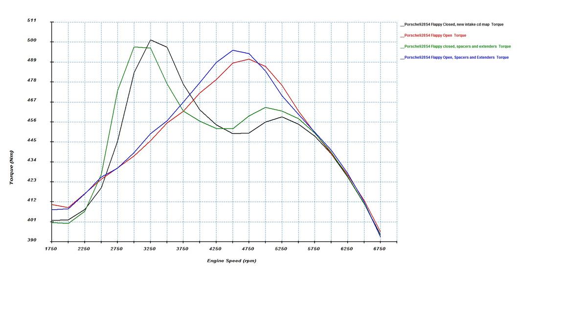
In the simulation, the spacers and extenders have the intended effect. Now, remember, you've checked the mental box that certifies you understand that this is not a dyno test and it's a simulation instead. Here' are the torque curves:
In the flappy closed mode, the plenum spacers and runner extenders shift the torque curve peaks to a lower rpm for three reasons. First, the plenum spacers increase the Helmholtz chamber volume, which reduces the tuned rpm. Second, the runner extenders increase the primary runner length, which also moves the resonator frequency to lower rpms. Third, the secondary ram pipe length (from the throttle body to the plenum) increases also, and that also brings down the tuned rpm.
In the flappy open mode, the torque peak shifts almost exclusively because of the longer primary runners. The plenum volume and secondary pipe length are close to irrelevant in the flappy open mode.
Who would want to shift the torque curve in this way? For one, someone who's got a turbo that spools at say 3250 rpms with stock manifold. Hey, I know someone like that! ;-) Better cylinder filling before that rpm point is really valuable, both directly because of higher torque and also because of extra exhaust gas produced that will now spool the turbine slightly earlier.
Another user might be someone with an automatic car who wants more torque down low and doesn't mind losing some of it in the 5000-6000 rpm band. That would depend on personal preferences, of course.
Something that this simulation does not capture and that can only be tested on a flow bench is that the spacers and extenders may help porting the intake manifold to flow better. The plenum spacer on the driver side will allow one to port the runner 5 entry to flow better. The runner extenders used without stock gaskets may allow one to port a smoother and longer transition from the intake manifold to the head, potentially increasing flow. I don't know if this kind of porting will help, the only way to guess more accurately is to flow them on a bench and the only way to know is to run a A-B-A dyno test. Wild speculation on my part, in other words.
To the extent I have a broader point here, it's this. There's a lot of debate here about whether spacers work or not. It's not that simple. I believe they do work in accomplishing certain things, and the main question is whether the user of the spacer understands or misunderstands what the spacers do to the intake manifold tuning and the torque curve.
Are you saying that your testing and R&D do not include any theoretical calculations?
I find this difficult to believe if that's the correct interpretation of your post.
In addition, it seems highly doubtful that the global engineering community would adopt highly complex software engineering tools such as Solidworks and use them to design complete engines that can be CAD tested based on all those physics theories and CFD theories around thermodynamics and heat management incorporated into the software. Not to mention material science theories of using dissimilar materials in the engine and having the software analyze the effects.
Granted, testing will validate a predetermined or accidental outcome. However, without the theory, there can be no expected or unexpected outcome.. Both theories and validation testing are needed in product development.
If your statement is correct, then it would mean that the simple scientific theory of the Otto cycle as isentropic and isochoric processes would be irrelevant, and the patent suit on four stroke engines among Otto/Deutz, de Rochas, Daimler and Maybach would also be irrelevant... No?
Sent from my iPhone using Rennlist
Virtually everything I do has some theoretical calculation.
That being said, my developmental path follows need. If I see a problem in the real world application and that problem limits me, I make a mental note to look into that problem, when I get a chance.
Example:
I build exhaust because I reached a roadblock. Is there theory and calculations in that exhaust? No simulations....No Pipemax....computer used for some references....mostly built from logic...and experience.
Not my first "exhaust rodeo". I built headers for the 3.6 liter 964 engines....and made mountains of scrap metal. The result: if you weren't running my headers and someone else was....you lost the "power advantage".
So, I draw from many different sources and experiences. Don't forget....all I've done, for the past 45 years, is this same dance.
All of which has nothing to do with what I said, which is:
Be careful not to turn theory and simulations into fact.
Can you expand on that? I am not sure I understand what you are saying....
I'll try. Some is easy and obvious, some not so much.
If one goes to buy an aftermarket high performance torque convertor, they will give you a range of the stall speed, completely dependent on the torque of the engine.
These Mercedes converters are no different. They have a specified stall speed, which is dependent on the output of the stock 928 engine in front of it.
I've used the "smaller" torque convertor with the higher stall speed in several late model applications to increase the stall speed and improve performance. When I build Andy's engine, with the high torque, I tried the same thing. Bad idea. The car would barely move when the power was rapidly applied. The convertor could not deal with the torque.
After trying all of the Mercedes converters that I had access to, I finally found one that would work with the increased torque and not just burn the transmission fluid between the two "fans" inside the convertor.
I've been playing with Hans's flanges for a week when I've had a spare moment.
Here's one issue with the 928 S4 intake and ports. To put it simply, they are very large. With the mild stock cams that don't have any overlap to speak off, these large runners and ports will produce a nice flat torque curve and acceptable pumping losses. However, one would have to really hot rod the stock engine to a very high level for the ports sizes to make sense with hot cams.
Here's what I mean. Suppose that we'll put in some sporty cams but nothing crazy:
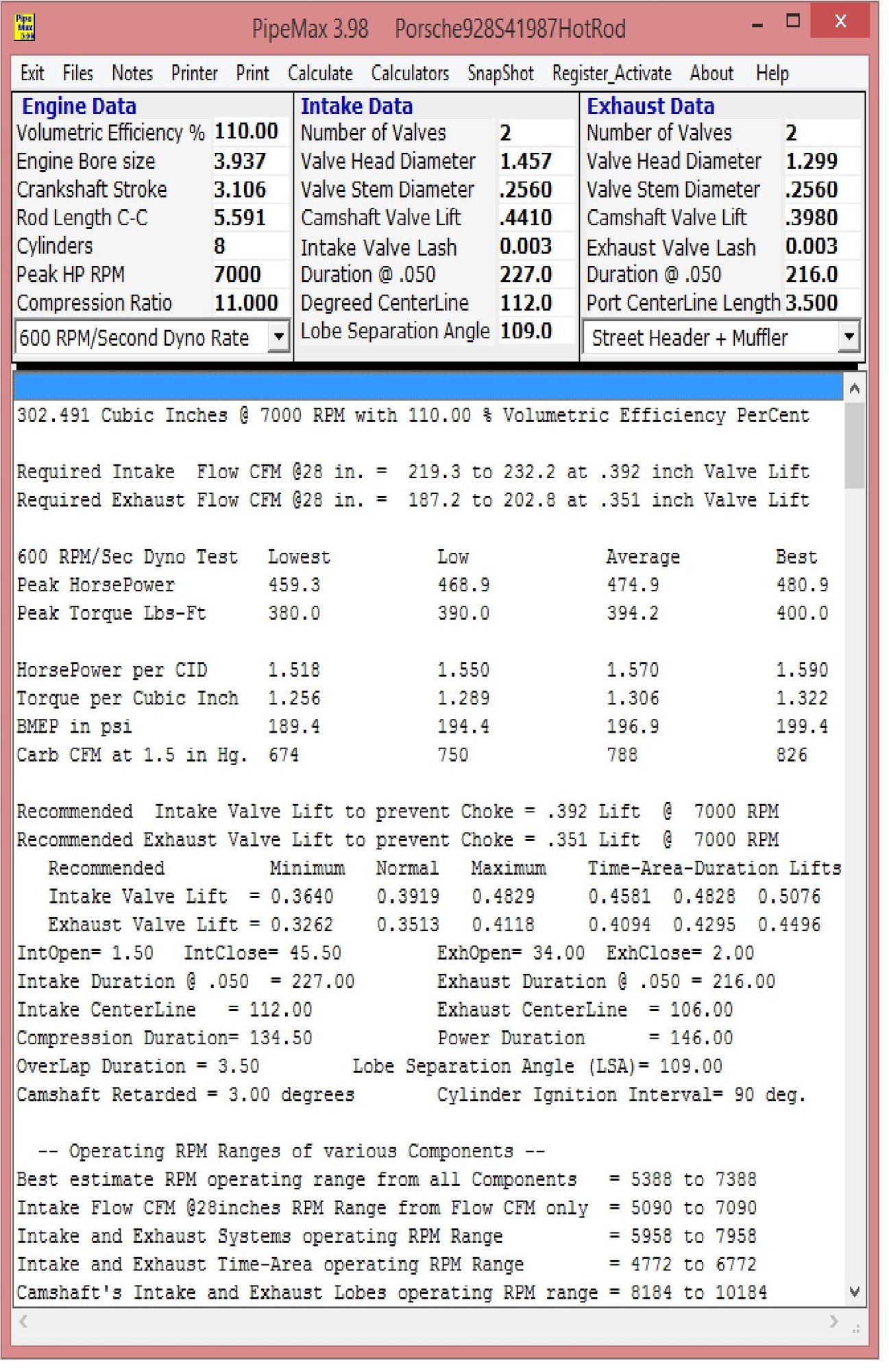
Furthermore, let's suppose we shoot for peak power at 7000 rpm and heroically assume we'll hit 110% VE at that rpm. To get there, one would have to get a lot of things right. Not implying it's easy, just saying suppose you could do it.
I run those number to pipemax:
Now, the program predicts that you'd make 450 hp at the crankshaft if you make 110% VE at 7000 rpm with a 5.0L engine. I don't think we see many normally aspirated 450hp 928 S4 5.0L engines running around, so let's say that this is probably towards the upper end of what people should expect to be able to do.
Now, to my point. Here's what pipemax recommends for the intake runners:
- Induction System Tuned Lengths - ( Cylinder Head Port + Manifold Runner )
1st Harmonic= 28.620 (usually this Length is never used)
2nd Harmonic= 16.244 (some Sprint Engines and Factory OEM's w/Injectors)
3rd Harmonic= 11.340 (ProStock or Comp SheetMetal Intake � best overall HP )
4th Harmonic= 8.926 (Single-plane Intakes , less Peak Torque � good HP )
5th Harmonic= 7.242 (Torque is reduced, even though Tuned Length)
6th Harmonic= 6.093 (Torque is reduced, even though Tuned Length)
7th Harmonic= 5.258 (Torque is greatly reduced, even though Tuned Length)
8th Harmonic= 4.625 (Torque is greatly reduced, even though Tuned Length)
Note> 2nd and 3rd Harmonics typically create the most Peak Torque
4th Harmonic is used to package Induction System underneath Hood
--- Cross-Sectional Areas at various Intake Port Velocities (@ 28 in.) ---
130 FPS at Intake Valve Curtain Area= 4.037 sq.in. at .441 Lift
158 FPS at Intake Valve OD Area and at Convergence Lift = .364
195 FPS 90% PerCent Rule Seat-Throat Velocity CSA= 2.701 sq.in.
--- 7000 RPM Intake Cross-sectional areas in Square Inches ---
350 FPS CSA= 1.502 Port has Sonic-Choke with HP Loss ( too fast FPS )
330 FPS CSA= 1.595 Port may have Sonic-Choke with HP Loss ( too fast FPS )
311 FPS CSA= 1.692 Highest useable Port velocity ( possible HP loss )
300 FPS CSA= 1.754 Smallest Port CSA ( Hi Velocity FPS � good TQ and HP )
285 FPS CSA= 1.846 Smallest Port CSA ( very good TQ and HP combination )
260 FPS CSA= 2.024 Recommended average Intake Port CSA (very good TQ and HP)
250 FPS CSA= 2.105 Largest recommended average Intake Port CSA ( good HP )
240 FPS CSA= 2.193 Largest recommended average Intake Port CSA (less Peak TQ)
235 FPS CSA= 2.239 Largest recommended Intake Port Gasket Entry area CSA
225 FPS CSA= 2.339 Largest Intake Port Gasket Entry CSA ( Slow FPS )
215 FPS CSA= 2.448 Possible Torque Loss with Reversion ( Slow FPS )
210 FPS CSA= 2.506 Torque Loss + Reversion possibility ( too slow FPS )
200 FPS CSA= 2.631 Torque Loss + Reversion possibility ( too slow FPS )
Note : these are calculated average Port cross-sectional areas and FPS
As a reference, the CSA of a 2" gauge 16 aluminum tube is about 2.75"! That matches the S4 intake port size fine, but it's way too large for a 450 hp V8.
Is pipemax wrong or are these intake ports and runners just too big for almost all 928 engines?
So I've been playing with cams, and for whatever it's worth, 11.2 mm / 10.1 mm of lift and 227/216 at .05" (1.27mm) is more lift and duration than ever ran in any of Anderson's or Fan's 6.5L motors. That would be awfully sporty on a 5-liter.
(Which begs the question of how much lift one can have on a 32V cam before you start to get the lobe too close to the edge of the 35 mm lifter? There's a picture of Ake's somewhere showing him having to enlarge the radius of the cuts in the heads for lobe clearance. That's 'crazy'!
More relevant to your modeling is Jim Corenman's 5-liter GT, which for a time ran Greg's intake in October 2013. Jim's cams are 10.7 and 10.1 lift, duration at 1mm are 220/220, LSA is 108. He's got good headers and exhaust, same ST-Alpha as me. 367 rwhp, 336 torque, STD. 8-10 less for SAE.
So that would be 420ish NA chp assuming 15% driveline loss.
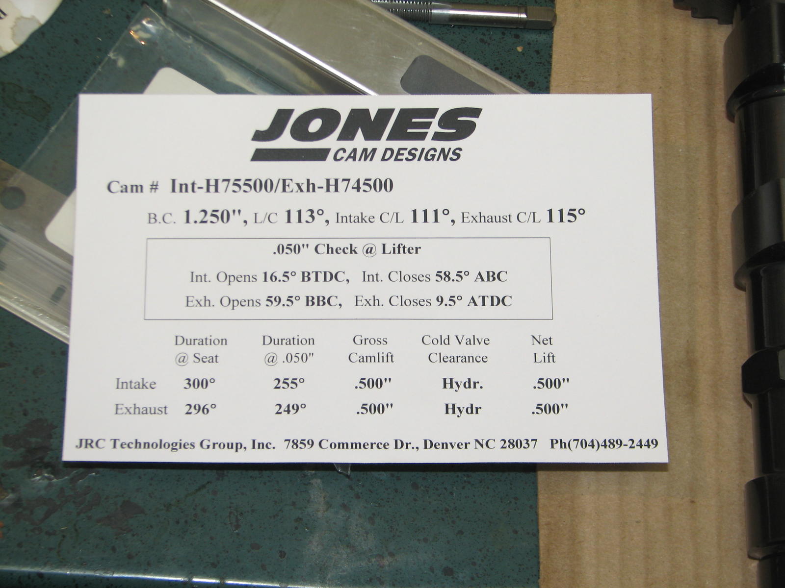
And this is what Simard runs on his ITB race car motor that "drives like a lamb":
I think that a lot of things impact the desired valve timing. The desired duration is influenced by the cylinder volume to valve throat area, higher number requiring more duration. The desired overlap is influenced by the cylinder volume to valve curtain area, higher number requiring more overlap (and lower LSA).
The peak lift is not very interesting number. What is much more interesting number is the valve lift at the peak piston speed. The maximum flow demand for intake port happens shortly after the maximum piston speed down in the bore (the short delay being equal to the time it takes for sound to travel from the piston to valve, which is a very short time). The valve has to be open high enough by that point for the head to supply what the piston wants. Additional lift after the peak piston velocity is not required, it's just whatever it ends up being when the valve is decelerated in a controlled fashion starting from the peak piston speed point. If you map those cam profiles, it would be interesting to know that when the are installed per designers spec of advance/retard, what is the lift at the peak piston speed point.
By the same logic, the head CFM flow is not that useful much above the lift that the camshaft provides at the maximum piston speed crank angle.
In terms of geometry, the peak lift has between little and nothing to do with how close to the edge of the lifter the cam lobe runs. The peak velocity determines how close the lobe goes. But you can lift the flat lifter at that peak velocity lmit for a long time without going over the edge. How these cams are designed is to first accelerate the valve about as fast as you can to the velocity that is limited by the lifter diameter and then the cam can dwell at that velocity up to the peak piston speed point after which it will be decelerated at the rate that is allowed by the negative acceleration limit. The negative acceleration limit is in turn determined by the redline rpm and the spring specification.
I've got one of Ake's tools for cutting the lobe reliefs into the heads. Recall that the relief geometry is not just determined by the peak lift, it's determined by half the base circle diameter plus the peak lift. There are some disadvantages to running a too small of a base circle, which is besides the point. However, it's just sufficient to say that whether you have to cut reliefs to the heads doesn't just depend on the peak lift.
GB's intake runners are IMO too big for a 5.0L but then again it wasn't designed for a 5.0L so that's no shocker there. The dyno graph from Jim Corenman's engine supports this view, that intake was not right for that car. The dyno from your bigger engine looked good, in contrast. And Jim Corenman's dyno with the stock intake S4 looks very nice.
I think the 8" and 12" runners of the S4 intake manifold have length and diameter that would support very high power levels if it weren't for the bends. The runners would just have to be straightened out and they would be good to go (and still have a too large of a diameter for most engines that have good headers and meaningful overlap).
To get these very high VE numbers, you have to use pulse tuning. Pulse tuning requires two things: meaningful camshaft overlap and _small enough pipes_. You need small enough pipes such that the peak velocities are high enough to generate strong pulses. With too big ports and pipes, you will not generate high velocities, and therefore you also don't generate strong pulses. This doesn't only apply to the intake, it also applies to the exhaust.
Originally Posted by Rob Edwards
So I've been playing with cams, and for whatever it's worth, 11.2 mm / 10.1 mm of lift and 227/216 at .05" (1.27mm) is more lift and duration than ever ran in any of Anderson's or Fan's 6.5L motors. That would be awfully sport on a 5-liter.
(Which begs the question of how much lift one can have on a 32V cam before you start to get the lobe too close to the edge of the 35 mm lifter? There's a picture of Ake's somewhere showing him having to enlarge the radius of the cuts in the heads for lobe clearance. That's 'crazy'!
More relevant to your modeling is Jim Corenman's 5-liter GT, which for a time ran Greg's intake in October 2013. Jim's cams are 10.7 and 10.1 lift, duration at 1mm are 220/220, LSA is 108. He's got good headers and exhaust, same ST-Alpha as me. 367 rwhp, 336 torque, STD. 8-10 less for SAE.
So that would be 420ish NA chp assuming 15% driveline loss.
Good point RE: the base circle reduction affecting relief geometry, it passed through my mind in thinking about my response but at the lifts I'm using the reliefs are a moot point.
Are you going somewhere with crazy cams that are going to necessitate lobe reliefs?
I've been playing with Hans's flanges for a week when I've had a spare moment.
Here's one issue with the 928 S4 intake and ports. To put it simply, they are very large. With the mild stock cams that don't have any overlap to speak off, these large runners and ports will produce a nice flat torque curve and acceptable pumping losses. However, one would have to really hot rod the stock engine to a very high level for the ports sizes to make sense with hot cams.
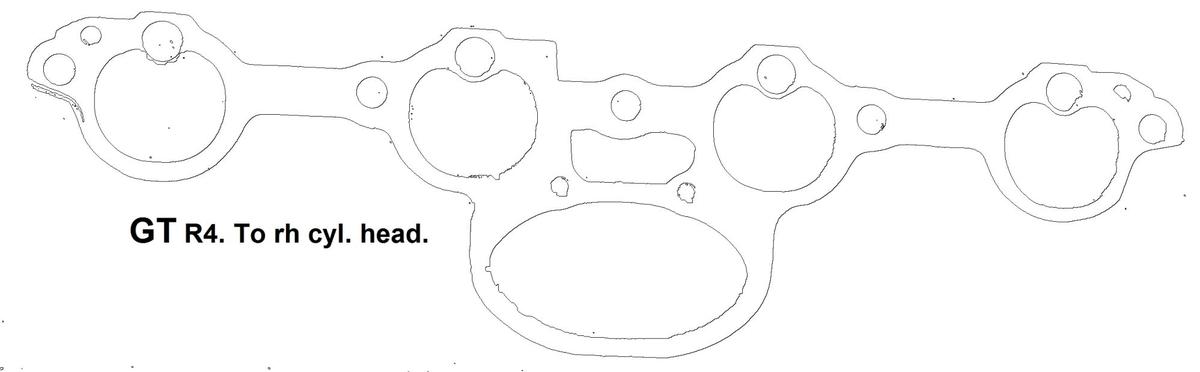
If you think these ports and intake are big.....you need to find a 968 (3.0 liter 4 cylinder) head and intake to look at.
While I do not happen to have a 968 head handy, here's a picture of a stock 968 intake gasket sitting on a stock 928 S4 intake port, as a reference.
I find the thought really interesting that Porsche, with their vast engineering skills and their huge testing facilities, not to mention their ability to have outside sources help them with engine development, would make the mistake of making port and intake systems too large....over and over again.
Certainly, if I had been involved in the development of the 968 engine, I would have certainly walked over to the shelf, plucked a stock 928 head off of it, and ran it on that engine, long before I went to the cost of having a completely new head designed and built.
The fact that they used bigger valves and made the port much, much larger must have some basis.
Here's what I think. I am not sure if it's correct or not, but I am sure that it's what I think! ;-)
If you can't use much camshaft overlap and headers, then big and slow ports give you decent top end performance, decent fuel economy, and a flattish torque curve without huge peaks and valleys. If you can use headers and and significant camshaft overlap, then you can make more power from the same displacement with smaller and faster ports.
What confounds me even more about your thought that the port is too big, is looking at the difference between the S3 and S4 engines.
The difference between these two engines is that the S4 has larger ports and bigger valves, while running a much milder camshaft than the S3. I believe the intake system design on an S3 is much more efficient than the more compact S4 intake (and thus unequal length runners), which should be a negative to the S4.
Yet the torque and horsepower is significantly better on the S4....enough that Porsche completely re-tooled and used the S4 design.....which for any automotive company, is a huge investment.
If I was the "bean counter" at Porsche, I would have certainly asked if the S3 head/intake could have been reworked to increase the flow to get the missing horsepower and torque from that design, before spending millions of dollars making a change to a completely different design.....
Seems, to me, like the bigger ports and bigger valves are exactly what was needed.

 02-05-2015, 06:12 PM