
S4 intake manifold facts and ideas
 02-04-2015, 12:12 PM
#196
Nordschleife Master
Thread Starter
 02-04-2015, 01:12 PM
#197
Addict
Rennlist Member
Rennlist Member
Join Date: Feb 2004
Location: Monterey Peninsula, CA
Posts: 2,374
Likes: 0
Received 16 Likes
on
12 Posts
I know there's a reason the in plug transducer was pricey!!
Good luck with the fitment, from the peanut gallery in CA, I send you faith, courage, and persistence!
From my useless brain, here's a thought.. A medical supplies place may have a surgical clamp that may give you the reach to insert the ring in the plug hole and screw it in the hole while having a firm grip. (My ex had lots of interesting surgical tools in her surgery cabinet) I would look for one that grips the inside of the ring and try not to mar the plug threads.
The plug can then be carefully threaded as normal, with care exercised with the piezoelectric leads.
Extracting the rings will be another matter... But you're not there yet.. Ultra copper may help here..
Cheers
Sent from my iPhone using Rennlist
Good luck with the fitment, from the peanut gallery in CA, I send you faith, courage, and persistence!
From my useless brain, here's a thought.. A medical supplies place may have a surgical clamp that may give you the reach to insert the ring in the plug hole and screw it in the hole while having a firm grip. (My ex had lots of interesting surgical tools in her surgery cabinet) I would look for one that grips the inside of the ring and try not to mar the plug threads.
The plug can then be carefully threaded as normal, with care exercised with the piezoelectric leads.
Extracting the rings will be another matter... But you're not there yet..
Ultra copper may help here..Cheers
Sent from my iPhone using Rennlist
02-04-2015, 01:56 PM
#198
Nordschleife Master
Thread Starter
Interesting findings, now we know why the 32V engine responds nicely to exhaust changes, specially good headers.
However, I remember reading one of the David Vizard books where he mentioned that dual-plane crank engines doesn't respond to primary pipe length changes
as long as they are in range of 28 - 40 inches. The MSDS primary lengths are 32, 26, 24 & 23 inches(valve face to collector), perhaps this will be the reason
for minimal gains together with uber short collector, go figure
Kind of OT for this thread, but talked some time ago with guy who has also experience of tuning stock ECUs. He mentioned that he's using WB datalogger which is capable of high enough
WBO2 sampling frequency to catch short AFR changes at higher rpms. Sometimes he has seen very quick rich conditions due to sudden exhaust suction, this will lead to lean cylinder AFR and possible knocks.
Only way is to add some fuel there even it looks like AFR is already in correct range from ECU point of view. At least, it will save lot's of expensive dyno time and you don't need to tune using trial and error method.
With stock cams that have relatively little overlap, long-tube headers probably helps bring the two 90-degree interference victim cylinders more in line with other cylinders. Long enough primary is all that is needed. That's something, but not much. Then there are some indirect gains from being able to set timing and fuel less conservatively. My uneducated guess is that these benefits are measurable but not huge. (Others have found some additional power from X-pipes and exhausts, no opinion on those.)
The situation changes with higher overlap cams. I think the potential gains from headers are larger when both the intake and exhaust valves are open together for a longer time. If you furthermore increase the static compression with the high-overlap, late IVC cams, there's yet more power available.
This is nothing revolutionary here, I think this is the consensus view on headers.
If one is making a set of headers, I'd consider welding O2 bungs to each of the primaries for testing purposes. They don't have to be exactly at the same spot, some can be closer to the port and others closer to the collector. They also don't need to be exactly at the usual orientation (10am-2pm) if they are only used for short periods of time for testing. Even if one has just one WBO2 sensor and controller, one can probably run a lot of WOT experiments that are informative, measuring the O2 in each runner by altering the sensor location.
Back to the stock intake...
02-04-2015, 11:57 PM
#199
Nordschleife Master
Thread Starter
As was quoted earlier in this thread, people who have extrude honed the S4 intake manifold have lost power. I've always wondered why that is, and as I am trying to learn this simulations software I decided to try extrude honing my model.
I tried extrude honing two intake models. The one has an intake tract with a good flow coefficient and the other has an intake tract with a bad flow coefficient. Blue and green simulate shapes that give good flow coefficients and red and black simulate shapes that give bad flow coefficients. Green and red lines have the runner ID extrude honed to 2mm larger.
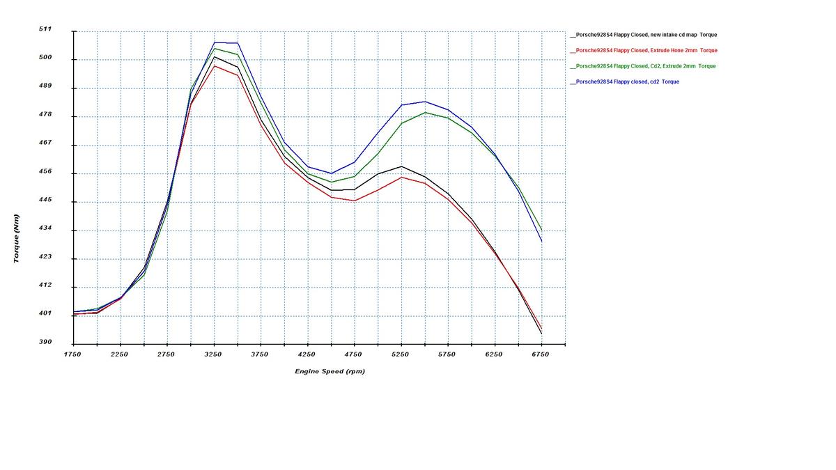
In both experiments, the runners that have been extrude honed larger (or otherwise expanded in size) by 2mm basically lose power across the board. At low rpms, there's little difference. At the first torque peak, the larger runners already lose, and the losses peak at about 5000 rpm. Only at 6300 rpm do the larger runners catch up again with the stock size runners and their very high rpm minimal torque advantage takes place at rpms that are beyond the peak power rpm.
The simulation results are consistent with experiments that find extrude honing hurts power. They are also consistent with our conjectures in other threads that the S4 intake ports and intake manifold runners are too large for the stock S4 engine.
I tried extrude honing two intake models. The one has an intake tract with a good flow coefficient and the other has an intake tract with a bad flow coefficient. Blue and green simulate shapes that give good flow coefficients and red and black simulate shapes that give bad flow coefficients. Green and red lines have the runner ID extrude honed to 2mm larger.
In both experiments, the runners that have been extrude honed larger (or otherwise expanded in size) by 2mm basically lose power across the board. At low rpms, there's little difference. At the first torque peak, the larger runners already lose, and the losses peak at about 5000 rpm. Only at 6300 rpm do the larger runners catch up again with the stock size runners and their very high rpm minimal torque advantage takes place at rpms that are beyond the peak power rpm.
The simulation results are consistent with experiments that find extrude honing hurts power. They are also consistent with our conjectures in other threads that the S4 intake ports and intake manifold runners are too large for the stock S4 engine.
02-05-2015, 03:28 AM
#200
Rennlist Member
Many thanks for these fascinating insights. Some time ago I started a thread to discuss why our motors were seemingly limited in terms of specific output. Not too difficult to see why our motors do not produce in excess fo 400crank BHP all things considered.
One thing that should not be overlooked is how many Vee 8 motors [today] have a hood line anywhere close to being as low as a 928? It would be interesting to compare with the latest "Vette" for instance.
your observation about the diamter of the runners is also interesting. I remember reading an interesting article about this wherein a Yamaha racer actually reduced the diameter of the stock runners to get the velocity up and made noticeably more power in the process.
I find that No. 6 then No. 2 seem to lead the charge knock wise being prone to onset in the 5300 rpm region. Doc Brown came up with the interesting observation that these cylinders run a bit hotter so try using a colder plug to even timing out a bit. Have not got round to that yet- I guess it is all interlinked. I have tended to assume these cylinder flow more air so comparatively leaner on a batch fired engine- thus Ken gets what he does by inventing a pseudo sequential firing system.
Seems we are progressively understanding ever more about these motors and their intrigues.
Rgds
Fred
 02-05-2015, 08:04 AM
#201
Nordschleife Master
Thread Starter
Coincidentally, all the above inefficient design decisions that make the stock engine a bad starting point for making normally aspirated power allow one to throw huge amounts of boost at the engine and make very nice boosted power number with completely stock components. By our experiments, the power that the S4 engine makes scales faster than one-for-one with manifold pressure.
I find that No. 6 then No. 2 seem to lead the charge knock wise being prone to onset in the 5300 rpm region... ...I have tended to assume these cylinder flow more air so comparatively leaner on a batch fired engine- thus Ken gets what he does by inventing a pseudo sequential firing system.
I don't understand why cylinder 2 would be particularly knock prone relative to other long-runner cylinders at any rpms. Yes, cylinder 2 fills very well in the 2500-4500 rpm range when the flappy is operated under the stock settings. This can be seen from the earlier IMEP graphs.
However, I think that the residual exhaust gas fraction is a much more significant driver of knock, because it heats up the charge and the max end gas temperature is a good predictor of knock. Cylinder 2 doesn't suffer from 180-degree or 90-degree exhaust blowdown interference.
The maximum unburned mixture temperature graphs suggest that the cylinder 2 at worst rpms shouldn't be any more knock prone than cylinder 3, for example. This stands in contrast with cylinders 6 which gets both a high pressure and high unburned mixture temperatures above 5000 rpm.
If you have logs in which cylinder 2 is statistically significantly more likely to knock than, say, cylinder 3, I'd like to know about it and try to reconcile it with the model.
02-05-2015, 01:28 PM
#202
Rennlist Member
I agree on cylinder 6 being knock prone.
I don't understand why cylinder 2 would be particularly knock prone relative to other long-runner cylinders at any rpms.
If you have logs in which cylinder 2 is statistically significantly more likely to knock than, say, cylinder 3, I'd like to know about it and try to reconcile it with the model.
If I can dig out anything of meaning from my ST2 data I will send it over to you.
Rgds
Fred
02-05-2015, 01:46 PM
#203
Addict
Rennlist Member
Rennlist Member
Join Date: Feb 2004
Location: Monterey Peninsula, CA
Posts: 2,374
Likes: 0
Received 16 Likes
on
12 Posts
Tuomo,
Have you looked into the setups that measure ionization energy across the plug gap? As I understand it, the signal measured between 10-60 degrees ATDC correlates closely to knock and pressure spikes.
Just curious, as this was proposed by several engineering researchers as an alternative to the Kistler/AVL in cylinder pressure sensors as they were very expensive. In addition, the data logger has to have a very high sample rate to gather enough data to make a knowledgeable determination..
Only professional grade loggers can sample at the higher levels, and they are also expensive.. One engineer for a development company mentioned 85k for a complete setup to monitor a 4 cylinder engine.!! Upside- all the power could be dialed in very easily, as you are able to tune each cylinder individually..
Ionization energy logging is an item I tagged for further examination as it showed promise in the technical papers I have read. If I remember correctly, there were 3 spikes in the combustion event, and the 3rd spike of ionic current measurement correlates to the pressure spike in the cylinder. I haven't explored the current measuring equipment, but I think Bosch Motorsports makes a coil with a pin that has a lead to measure the ionization energy. However, this requires 1 coil per cylinder so not LH friendly.
I plan to use COP, so I thought it may be an easier fit to my data logger, even if I had to buy a channel expander, it should be decent enough and fit with the dual channel Lambda enabled in my ECU. This analysis coupled with individual fuel and timing trims should enable tweaks to optimize the system..
Just a thought....
Best regards
Sent from my iPhone using Rennlist
02-05-2015, 01:58 PM
#204
Inventor
Rennlist Member
Rennlist Member

I have gone back to the basics and am working more incrementally with self-learning code that works well enough for the chip. I am running a 'simpler' 224 cell/RPM all-cylinder learned WOT ignition map while still looking forward to stable per-cylinder or 2-cyl group mapping. I hope to eventually generate enough data to be able to employ some of Tuomo's theories on cylinder grouping.
02-05-2015, 02:19 PM
#205
Nordschleife Master
Thread Starter
Do not forget Greg's observation that 6 & 2 run a bit hotter than the other cylinders- I assumed that was down to cooling performance but maybe it is also to do with combustion dynamics- a leaner mix usually runs hotter than an overly rich mix which cools things down a bit. If I can dig out anything of meaning from my ST2 data I will send it over to you.
If anyone posts WOT knock frequencies per cylinder per rpm form their stockish S4 data logs, I can try to correlate those with the simulations.
02-05-2015, 02:26 PM
#206
Nordschleife Master
Thread Starter
Have you looked into the setups that measure ionization energy across the plug gap? As I understand it, the signal measured between 10-60 degrees ATDC correlates closely to knock and pressure spikes.
Just curious, as this was proposed by several engineering researchers as an alternative to the Kistler/AVL in cylinder pressure sensors as they were very expensive. In addition, the data logger has to have a very high sample rate to gather enough data to make a knowledgeable determination..
Only professional grade loggers can sample at the higher levels, and they are also expensive.. One engineer for a development company mentioned 85k for a complete setup to monitor a 4 cylinder engine.!! Upside- all the power could be dialed in very easily, as you are able to tune each cylinder individually..
Ionization energy logging is an item I tagged for further examination as it showed promise in the technical papers I have read. If I remember correctly, there were 3 spikes in the combustion event, and the 3rd spike of ionic current measurement correlates to the pressure spike in the cylinder. I haven't explored the current measuring equipment, but I think Bosch Motorsports makes a coil with a pin that has a lead to measure the ionization energy. However, this requires 1 coil per cylinder so not LH friendly.
I plan to use COP, so I thought it may be an easier fit to my data logger, even if I had to buy a channel expander, it should be decent enough and fit with the dual channel Lambda enabled in my ECU. This analysis coupled with individual fuel and timing trims should enable tweaks to optimize the system..
Yes, this is the sort of technology that lends itself to coil on plug systems the best.
My sense however is that as an R&D tool the ion sensing signal is a lot more open to interpretation than a simple pressure trace.
02-05-2015, 02:36 PM
#207
Nordschleife Master
Thread Starter
I found that is a lot more ignition advance possible on some cylinders, but I haven't been able to implement it effectively. Inserting per-cylinder retard, based on the factory code, was a bad idea. I 'wasted' my holiday break chasing ghosts and nearly drove myself around the bend with the non-stop coding and testing...but it's all good. . I have gone back to the basics and am working more incrementally with self-learning code that works well enough for the chip. I am running a 'simpler' 224 cell/RPM all-cylinder learned WOT ignition map while still looking forward to stable per-cylinder or 2-cyl group mapping. I hope to eventually generate enough data to be able to employ some of Tuomo's theories on cylinder grouping.
. I have gone back to the basics and am working more incrementally with self-learning code that works well enough for the chip. I am running a 'simpler' 224 cell/RPM all-cylinder learned WOT ignition map while still looking forward to stable per-cylinder or 2-cyl group mapping. I hope to eventually generate enough data to be able to employ some of Tuomo's theories on cylinder grouping. (1) Do you have enough data logs that would allow you to compute an 8 by N table of knock probabilities (knock combustion cycles / total combustion cycles) at WOT? That is, N rpm groups as columns and 8 cylinders as rows? If you do, can you post that table? It doesn't really matter what the timing curve is as long as there are enough knocks. One can just demean the cells in each column by the column average (to focus on differences between cylinders at that rpm, instead of absolute level of knocks).
(2) I understand that a self-learning system can be tricky to update correctly. However, can you do something much simpler: Can you put in a constant additive term to the spark retard which is looked up from an 8 by N table of constants and applied conditional on WOT? N being the rpm dimension and 8 being the cylinder number. Even if that table is applied at WOT only regardless of load, it'll solve most of the imbalance problems. There would be no need for any self-learning features, these differences between cylinders aren't going to change much as long as the engine hardware isn't changed much.
02-05-2015, 02:43 PM
#208
Rennlist Member
Center cylinders run hotter in most V8's, but #3 and #2 are both center cylinders. I haven't been able to come up with a theory why #2 would knock easier than #3. I also haven't seen it in my tuning efforts, but then again my exhaust manifolds are nothing like the stock exhaust manifold.
If anyone posts WOT knock frequencies per cylinder per rpm form their stockish S4 data logs, I can try to correlate those with the simulations.
If anyone posts WOT knock frequencies per cylinder per rpm form their stockish S4 data logs, I can try to correlate those with the simulations.
Rgds
Fred
02-05-2015, 04:26 PM
#209
Former Sponsor

While theory and simulations are fun, one needs to be careful to not turn those into fact....which seems like what is happening, in this thread.
Actual real life dyno testing trumps theory and any simulation one can find.
And I've done that testing....over and over again. So, for those of you that haven't been following what I've been doing for the past 10 years....or just got out of a cave in the mountains.....
A hand ported and 2R manifold (which only addresses the bellmouths and as far as one can reach into the ports with an 8" carbine cutter), with stock exhaust and cats will "support" 340 rwhp (in a 928 with an automatic) on a 6.5 liter stroker. (That's right around 400hp flywheel HP.) Absolutely nothing that I did for 6 months of solid research and development made any change.....the dyno printouts were virtually exactly the same....to the point of being absurd. Cam timing changes, changing camshafts, changing intake plenum spacers, larger butterfly, dramtically altering the lower plenum, changing the injectors, tuning for days and days on end made any difference. The only change that did anything at all was a 10 rwhp loss when I installed a smaller resonator exhaust system, from the cats back.
When we finally bolted on my highly researched and developed headers and exhaust system (with cats), we were able to "move" the power up to the 360hp (rwhp) range....but repeating all of the earlier tests, the engine was absolutely "stuck" at that power output.
I believe two things limited that engine...and the testing was planned, until the car had a terminal incident.
I believe the driveshaft and possibly the torque convertor had reached the limit of what they could transmit. There was also a possibility that a change to the 4R manifold would have helped.
I have bolted on my prototype custom manifold onto a well tuned GT....and the results were pretty spectacular...but I doubt that an intake change on a stock 5.0 engine is going to do very much.
I will find out, because I test....and test....and test. Real world, no theory, no "dyno cheating" glory testing.
02-05-2015, 04:47 PM
#210
Instructor
Join Date: Aug 2013
Posts: 143
Likes: 0
Received 0 Likes
on
0 Posts
Research and development should always include theory and basic calculations/simulations in addition to testing. Just testing and testing without the theoretical knowledge is not "research and development".