
S4 intake manifold facts and ideas

 12-18-2013, 11:56 AM
#152
Pro
This is the solution:
https://rennlist.com/forums/8147443-post32.html
premade, all you need to do is get the intake manifold stacks to mate to it, and get a Y pipe for the intake so it uses a big throttle body and then the stock maf.. piece of cake!
https://rennlist.com/forums/8147443-post32.html
premade, all you need to do is get the intake manifold stacks to mate to it, and get a Y pipe for the intake so it uses a big throttle body and then the stock maf.. piece of cake!

Last edited by UpFixenDerPorsche; 03-12-2014 at 07:47 AM.
12-18-2013, 04:58 PM
#153
Rennlist Member

Join Date: Jul 2002
Location: Deep in the Heart of Texas!
Posts: 3,267
Likes: 0
Received 5 Likes
on
4 Posts
Interesting thread. I've wondered a long time why Porsche changed from the S3 'pipe organ' manifold to the S4 version after only two years and not that many engines, since the first 32V was only sold in US, Japan and maybe a few other countries.
I doubt they considered the S3 design flawed but perhaps some new technology like resonant induction with flappy valve or individual cylinder knock management with EZK motivated them to do a brand new solution? As previous posts confirm, we know they weren't looking for more top-end power with the direction they chose for 928 cams, so maybe the answer is they were focused on torque. That seems consistent with the 'Variocam' (928) and 'Varioram' (911) development underway around that same time for other models.
I doubt they considered the S3 design flawed but perhaps some new technology like resonant induction with flappy valve or individual cylinder knock management with EZK motivated them to do a brand new solution? As previous posts confirm, we know they weren't looking for more top-end power with the direction they chose for 928 cams, so maybe the answer is they were focused on torque. That seems consistent with the 'Variocam' (928) and 'Varioram' (911) development underway around that same time for other models.
Last edited by Tom in Austin; 12-18-2013 at 06:05 PM.
12-18-2013, 08:57 PM
#154
Rennlist Member
I hope someday before i die, someone uses one of these intake manifolds on the stock 5 liter and watch it wake up. i still cant believe no one has run and dynoed one.
12-19-2013, 11:24 PM
#155
Pro
Couldn't agree more Mark.
IMHO Porsche managed to make "the south end of a northbound horse".
Did you receive my email of a few days ago? (Send via this board).
Cheers
JC
03-12-2014, 07:19 AM
#156
Instructor
Join Date: Oct 2005
Location: Finland
Posts: 137
Likes: 0
Received 0 Likes
on
0 Posts
Some pictures requested by Tuomo.
Original idea of modifying S4 intake game from Jim Morton who modified GT intake for Kaos engine. I don't have current flow numbers, it was around 290cfm one time while tested in flowbench,
but variation between tubes was still more than 10cfm. Got frustunated and made my own flowbench from industrial vacuum cleaner, piece of 80mm plastic tube and transparent hose, that worked pretty well
If the worst stock intake tube is able to flow around 270cfm, it should be able to give more than 500hp, but that's not the case. There must be hell lot's of restriction somewehere.
When I started to work with turn from throttleplate to oval tube, I found that already well flowing tubes worked even better and I need to reduce the static flow for those.
While driving the car without flow reductions on those tubes, well flowing cylinders started to knock right after switching to WOT. This told me that I'm on right track, there is bunch of hiding improvement available.
When the flow demand is very high, the small plenum isn't able to supply requested amount and it starts to draw more air through throttle plate. If TP to plenum path is restrictive or TP is too little, the VE, torque and power starts to reduce rapidly.
Therefore the TP to plenum path ans TP size should be optimal as well, that wasn't the case with stock intake.
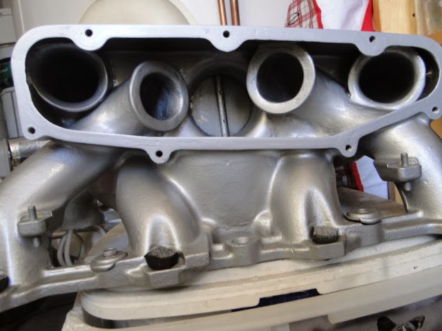
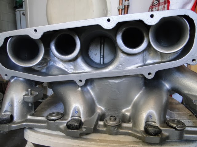
Notice also turn from oval tube to plenum, the radius has been enlarged to help flow for tubes like 5,8,6 & 7. All extra casting removed from behind the tubes to allow flow to turn from behind to front of bellmouth and so on..
The #5 and #8 bellmouths have been grinde to elliptical shape, to maximize flow and make them work equally with others.
The torque is now increasing rapidly after 2400rpm due to modified intake, low plenum resonance rpm point and reduced port CSA. As a result of this, engine was knocking even in cruise map area. The fix was to back off timing slightly there.
Need to make testing with flappy removed etc. to smoothen the torque lag. The whole project should be ready for dyno at upcoming driving season.
Sorry about quality of photos, took them quickly at late yesterday.
https://plus.google.com/photos/11456...CP7u0MvSsKS5Yw
Original idea of modifying S4 intake game from Jim Morton who modified GT intake for Kaos engine. I don't have current flow numbers, it was around 290cfm one time while tested in flowbench,
but variation between tubes was still more than 10cfm. Got frustunated and made my own flowbench from industrial vacuum cleaner, piece of 80mm plastic tube and transparent hose, that worked pretty well
If the worst stock intake tube is able to flow around 270cfm, it should be able to give more than 500hp, but that's not the case. There must be hell lot's of restriction somewehere.
When I started to work with turn from throttleplate to oval tube, I found that already well flowing tubes worked even better and I need to reduce the static flow for those.
While driving the car without flow reductions on those tubes, well flowing cylinders started to knock right after switching to WOT. This told me that I'm on right track, there is bunch of hiding improvement available.
When the flow demand is very high, the small plenum isn't able to supply requested amount and it starts to draw more air through throttle plate. If TP to plenum path is restrictive or TP is too little, the VE, torque and power starts to reduce rapidly.
Therefore the TP to plenum path ans TP size should be optimal as well, that wasn't the case with stock intake.
Notice also turn from oval tube to plenum, the radius has been enlarged to help flow for tubes like 5,8,6 & 7. All extra casting removed from behind the tubes to allow flow to turn from behind to front of bellmouth and so on..
The #5 and #8 bellmouths have been grinde to elliptical shape, to maximize flow and make them work equally with others.
The torque is now increasing rapidly after 2400rpm due to modified intake, low plenum resonance rpm point and reduced port CSA. As a result of this, engine was knocking even in cruise map area. The fix was to back off timing slightly there.
Need to make testing with flappy removed etc. to smoothen the torque lag. The whole project should be ready for dyno at upcoming driving season.
Sorry about quality of photos, took them quickly at late yesterday.
https://plus.google.com/photos/11456...CP7u0MvSsKS5Yw
03-12-2014, 01:55 PM
#157
Rennlist Member
Join Date: Oct 2009
Location: Michigan... Grand Rapids
Posts: 758
Likes: 0
Received 2 Likes
on
1 Post
So I said WTH this afternoon and bought a Cayenne intake manifold. The head openings are definitely larger on the Cayenne, but everything else seems to layout fairly close. It should be fairly easy to machine an adapter plate, and bolt it on. The price was right, and it came with the injectors, rails, throttle body, bolts, ect... Wish me luck!!! I will put it on my stock white 89 and see what the dyno says first before strapping on a supercharger
03-12-2014, 02:31 PM
#159
Nordschleife Master
Thread Starter
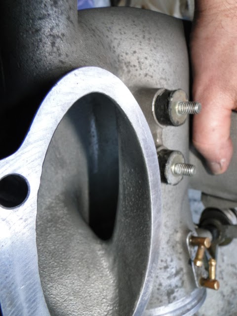
Here's a comparison of an unmodified intake with Simo's intake:
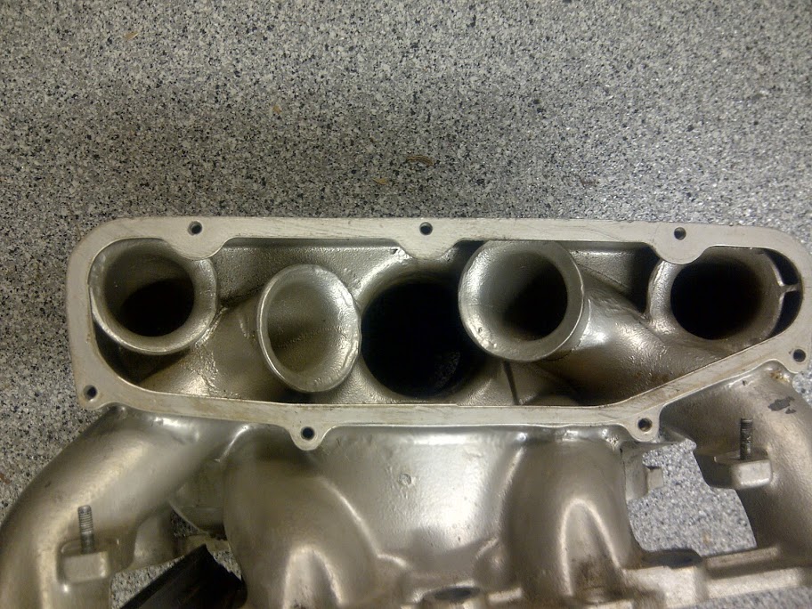
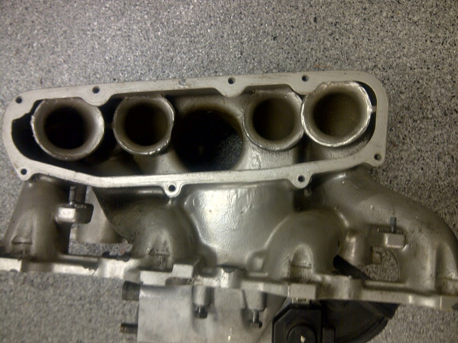
The long center runners have been constrained with something (I am guessing epoxy aluminum putty but I don't rally know). The short end runners have their bellmouths opened up.
Questions to Simo:
- Did adding the restrictors to some runners and enlarging others to ellipses equalize the steady state flow?
- Are you measuring the steady state flow with or without the plenum covers on? If you did both, does the cover further exacerbate the flow differences between runners?
- How much more will the intake manifold, stock or modified, flow with the lower throttle body element removed vs. thru it?
Last edited by ptuomov; 03-12-2014 at 08:08 PM.
03-13-2014, 04:54 AM
#160
Instructor
Join Date: Oct 2005
Location: Finland
Posts: 137
Likes: 0
Received 0 Likes
on
0 Posts
Tuomo,
Adding the restrictors and enlarging/making elliptical the inputs of entries did equalize the flow. First I worked with throttlebody and turn from oval tube to plenum
and then started to look for each intake tube issues. Some of the tubes needs entry to be reduced 1 - 3mm to balance the flow. Reducing the diameter is the most powerfull way to reduce flow.
I had plenum covers, throttlebody and even rubber elbow installed while making measurements. This is the only way to get correct idea of flow or it's restrictions,IMHO.
I had throttlebody installed with each flowbench test, the biggest problem is to make tubes 5 & 8 to flow as much as possible. Once you think you have done everythng with those,
you can start working with other tubes by reducing or increasing the flow of them.
Advancing the flow by working with throttlebody and upper oval tube turn, gives you possibility to reduce the flow on some of the tubes and even still they may flow more than stock, not much but..
The material thickness will be limiting factor in throttlebody and oval tube to plenum turn, this needs to be kept in mind and measured way or other.
There is a chance to add more material to outside of throttlebody turns(TIG), but didn't want to go that far, like to keep overall look stock.
You need to make each turn having smooth and large radius to give air more time to turn.
Try to smooth every corner and step inside the plenum, the air is also traveling quickly back and through inside the plenum.
There is a chance to make number 5 & 8 even better by enlargening the turn radiuses inside the intake tube. Goodson is selling grinds with longer safts to do this,
but there is always something to make better and decided to leave it. BTW. this trick is powerfull..
Finally,
It's not going to be any race intake, it will have less restrictions and balanced flow. This should help with pushing ignition advance as far as possible
03-13-2014, 05:24 AM
#161
Nordschleife Master
So I said WTH this afternoon and bought a Cayenne intake manifold. The head openings are definitely larger on the Cayenne, but everything else seems to layout fairly close. It should be fairly easy to machine an adapter plate, and bolt it on. The price was right, and it came with the injectors, rails, throttle body, bolts, ect... Wish me luck!!! I will put it on my stock white 89 and see what the dyno says first before strapping on a supercharger
Is the intake you bought from a 4.5 or 4.8L cayenne? (both make more power than an S4).
03-13-2014, 08:26 AM
#162
Nordschleife Master
Thread Starter
Simo --
The reason I am asking about flowing the top and bottom parts separately is that I think this could be helpful in separating where the restrictions and imbalances are coming from. If you flow the top part without the bottom part, how much will it flow and how unequal are the flow numbers per cylinder, compared to with the bottom TB part on? You'd need short oval extensions to simulate the missing parts, but given what you've already done with modeling clay that shouldn't be a problem.
Did you consider adding plenum spacers to the top intake manifold? Permanently attached plenum spacers would allow you to greatly unshroud the end cylinder runners. This is because permanent attachment would allow you to cut off some of gasket flange around the bolt holes.
One way to reduce the flow to center cylinders and increase it to the end cylinders would be to fill in some material behind the center cylinder trumpets. More material behind the center trumpets should by my logic speed up the air flow over the center trumpets and therefore reduce the flow to the center trumpets and increase the flow to the end trumpets.
I notice that you have filled some of the cavities on the wall between the runners. What's the motivation for that? The plenum volume is a tuning parameter for this manifold with flappy closed. Filling in the plenum will increase the resonance point. Is this intentional, or are you planning to recover the volume by adding plenum spacers? Or did the removing of casting behind the end runners offset the volume that you filled?
It makes sense that if you've filled in net the plenums to be a bit smaller, the first resonance peak should move to a slightly bit higher rpm.
Do I understand you correctly that after the runners have been equalized, you think this driver-side turn from the throttle body is the main restriction in the whole manifold?
If so, were you able to measure a benefit form your modifications, specifically to this spot? That is, does this driver side turn now flow more on a flow bench than it did before?
Best, Tuomo
Tuomo,
Adding the restrictors and enlarging/making elliptical the inputs of entries did equalize the flow. First I worked with throttlebody and turn from oval tube to plenum
and then started to look for each intake tube issues. Some of the tubes needs entry to be reduced 1 - 3mm to balance the flow. Reducing the diameter is the most powerfull way to reduce flow.
I had plenum covers, throttlebody and even rubber elbow installed while making measurements. This is the only way to get correct idea of flow or it's restrictions,IMHO.
I had throttlebody installed with each flowbench test, the biggest problem is to make tubes 5 & 8 to flow as much as possible. Once you think you have done everythng with those,
you can start working with other tubes by reducing or increasing the flow of them.
Advancing the flow by working with throttlebody and upper oval tube turn, gives you possibility to reduce the flow on some of the tubes and even still they may flow more than stock, not much but..
The material thickness will be limiting factor in throttlebody and oval tube to plenum turn, this needs to be kept in mind and measured way or other.
There is a chance to add more material to outside of throttlebody turns(TIG), but didn't want to go that far, like to keep overall look stock.
You need to make each turn having smooth and large radius to give air more time to turn.
Try to smooth every corner and step inside the plenum, the air is also traveling quickly back and through inside the plenum.
There is a chance to make number 5 & 8 even better by enlargening the turn radiuses inside the intake tube. Goodson is selling grinds with longer safts to do this,
but there is always something to make better and decided to leave it. BTW. this trick is powerfull..
Finally,
It's not going to be any race intake, it will have less restrictions and balanced flow. This should help with pushing ignition advance as far as possible
Adding the restrictors and enlarging/making elliptical the inputs of entries did equalize the flow. First I worked with throttlebody and turn from oval tube to plenum
and then started to look for each intake tube issues. Some of the tubes needs entry to be reduced 1 - 3mm to balance the flow. Reducing the diameter is the most powerfull way to reduce flow.
I had plenum covers, throttlebody and even rubber elbow installed while making measurements. This is the only way to get correct idea of flow or it's restrictions,IMHO.
I had throttlebody installed with each flowbench test, the biggest problem is to make tubes 5 & 8 to flow as much as possible. Once you think you have done everythng with those,
you can start working with other tubes by reducing or increasing the flow of them.
Advancing the flow by working with throttlebody and upper oval tube turn, gives you possibility to reduce the flow on some of the tubes and even still they may flow more than stock, not much but..
The material thickness will be limiting factor in throttlebody and oval tube to plenum turn, this needs to be kept in mind and measured way or other.
There is a chance to add more material to outside of throttlebody turns(TIG), but didn't want to go that far, like to keep overall look stock.
You need to make each turn having smooth and large radius to give air more time to turn.
Try to smooth every corner and step inside the plenum, the air is also traveling quickly back and through inside the plenum.
There is a chance to make number 5 & 8 even better by enlargening the turn radiuses inside the intake tube. Goodson is selling grinds with longer safts to do this,
but there is always something to make better and decided to leave it. BTW. this trick is powerfull..
Finally,
It's not going to be any race intake, it will have less restrictions and balanced flow. This should help with pushing ignition advance as far as possible
03-13-2014, 11:00 AM
#163
Rennlist Member
Join Date: Oct 2009
Location: Michigan... Grand Rapids
Posts: 758
Likes: 0
Received 2 Likes
on
1 Post
Hans and I are working together to come up with a good adapter plate
The openings are larger on the Cayenne, but all the locations initally appear very very close
03-13-2014, 11:57 AM
#164
Nordschleife Master
Thread Starter
What's the Cayenne bore spacing, or more importantly intake port spacing? Very few V8's are as far apart as the 928 and it's 122mm bore spacing.
03-13-2014, 12:20 PM
#165
Rennlist Member
Join Date: Oct 2009
Location: Michigan... Grand Rapids
Posts: 758
Likes: 0
Received 2 Likes
on
1 Post