
S4 intake manifold facts and ideas
 05-30-2013, 11:49 PM
#136

I want to make two of what I showed, and then put a D plenum on each side, with a forward facing entry for air.
 05-31-2013, 12:08 AM
#137
Nordschleife Master
Thread Starter
(I thought you) measured it recently, but this is not to give me more space - its to reorient and completely change the place at which air enters the runners - and in that way completely remove the side plate restriction, as well as the Throttle body position, which I don't like,
I want to make two of what I showed, and then put a D plenum on each side, with a forward facing entry for air.
I want to make two of what I showed, and then put a D plenum on each side, with a forward facing entry for air.
05-31-2013, 12:32 AM
#138
Addict
Rennlist Member
Rennlist Member
Join Date: Oct 2003
Location: Gone. On the Open Road
Posts: 16,466
Received 1,622 Likes
on
1,059 Posts
I'm armed with college-level fluid dynamics and English as a second language. But, unlike Tuomo, the powder in the bullets in my gun is so old that it won't ignite and I'm left with only the memory of what it sounded like...
Nevetheless, to me, simplifying the contexts of N/A and FI to just pressure sounds like modeling air as one would water. Whereas seeing what it does on a flow bench is an observation of air acting according to its nature as a compressible fluid.
05-31-2013, 06:54 AM
#139
Instructor
Join Date: Oct 2005
Location: Finland
Posts: 137
Likes: 0
Received 0 Likes
on
0 Posts
It's the piston which is sucking or pulling the air into cylinder. Top of this is the intake pumping process which is actually very strong. Pressurized plenum may help there, but isn't the major thing.
I like the following little document very much, don't know who wrote it but he really knows the stuff: http://www.google.pl/url?sa=t&rct=j&...Wu_98Q&cad=rja
When the valve opens, the air doesn�t flow in, it decompresses into the low-pressure region. All the air on the upstream side of the moving disturbance boundary is completely isolated and unaffected by what happens on the downstream side of it. The air at the runner entrance does not move until the wave reaches all the way to the end. It is only then that the entire runner can begin to flow. Up until that point all that can happen is the higher pressure gas filling the volume of the runner decompresses or expands into the low-pressure region advancing up the runner. (Once the low pressure wave reaches the open end of the runner it reverses sign, the inrushing air forces a high pressure wave down the runner.)
Conversely the closing of the valve does not immediately stop flow at the runner entrance, which continues completely unaffected until the signal that the valve has closed reaches it. The closing valve causes a buildup of pressure which will travel up the runner as a positive wave. The runner entrance continues to flow at full speed, forcing the pressure to rise until the signal reaches the entrance. This very considerable pressure rise can be seen on the graph below. At the closing of the intake valve, pressure rises far above atmospheric.
It is this phenomenon that enables the so-called �ram tuning� to occur and it is what is being �tuned� by tuned intake and exhaust systems. The principal is the same as in the water hammer effect so well known to plumbers. The speed that the signal can travel is the speed of sound in the gas inside the runner. The boundary between the wave affected gas and unaffected gas could be compared to the event horizon of a black hole.
This is why port/runner volumes are so important. The volumes of successive parts of the port/runner control the flow during all transient periods. That is any time a change occurs in the cylinder whether positive or negative. Such as when the piston reaches maxumum speed half way down the stroke.
The wave/flow activity in a real engine is vastly more complex than this but the principle is the same.
At first glance this wave travel might seem to be blindingly fast and not very significant but a few calculations shows the opposite is true. In an intake runner at room temperature the sonic speed is about 1100 feet per second and will traverse a 12 inch port/runner in 0.9 milliseconds. The engine using this system, running at 8500 RPM, takes a very considerable 46 crank degrees before any signal from the cylinder can reach the runner end. 46 degrees during which nothing but the volume of the port/runner supplies the demands of the cylinder. This not only applies to the initial signal but to any and every change in the pressure or vacuum developed in the cylinder.
As John pointed out and some of my previously sent documents proved, the vawe pulse effect will change the steady flow effect the way, that even not so well flowing port would still work quite well...
Also, the NA and boosted engine will work under same physical laws what comes to plenum and intake path functionality. The main difference is the compressed air in boosted application, which means that it has higher density.The velocity of intake port in both cases will be the same, but VE will be higher as in boosted application the air density is higher.
When velocity in port will exceed 0,55 mach, the port starts to choke. In this case, the velocity will still increase, but air starts to stretch and result is that the air has less density. This is the point, wehere power starts to drop quickly.
06-02-2013, 03:22 AM
#140
Rennlist Member
MK, for the life of me, I am tired of explaining that it is not possible. I bought an entire assembly from a crashed E39 M5 for my project. The 928 bonnet (hood for you 'mericans ) line does not allow for the ITBs on cylinders 1 and 5, and for their trumpets without major mods to the bonnet and the silhouette of the car, which kind of defeats the purpose. There is no space to mount the actual air box on top. It is that simple. Trust me, when it comes to being ingenious with our 928 race engine, we are hard to beat and we still had to be inventive to make the ITBs fit...
We even made more horsepower on a real dyno than you, from a 5.4ltrs block...
) line does not allow for the ITBs on cylinders 1 and 5, and for their trumpets without major mods to the bonnet and the silhouette of the car, which kind of defeats the purpose. There is no space to mount the actual air box on top. It is that simple. Trust me, when it comes to being ingenious with our 928 race engine, we are hard to beat and we still had to be inventive to make the ITBs fit... We even made more horsepower on a real dyno than you, from a 5.4ltrs block...
this will solve all the problems and give some big HP gains.
as far as the 5.4 liter making more power than my engine.... my engine is fed by all stock , no change, components. im sure with a shark tune or some changes to cams, some decent gains could get it up to 400-410rwhp like we have seen on other 6.4 liter engines. But, the intake is the element that is most interesting as Anderson and Fan bolted on a type similar to what im suggesting and gained near 100hp.(no other changes). so all the theory in the world aside, the gains were made with intake only over the stock stuff.
As far as the flappy, again, its only needed for drivability , in racing or dyno comparisons for peak HP, its meaningless, as it only helps below the "racing" rpm range (i.e. below 4500rpm)
as far as the semantic discussion between GB and others, its the pressure that does the work, vacuum does nothing. air moves to differential pressure. forced or not, the flow acts the same.
Mk
06-02-2013, 10:12 AM
#141
Nordschleife Master
Thread Starter
[Quoting a doc]
Conversely the closing of the valve does not immediately stop flow at the runner entrance, which continues completely unaffected until the signal that the valve has closed reaches it. The closing valve causes a buildup of pressure which will travel up the runner as a positive wave. The runner entrance continues to flow at full speed, forcing the pressure to rise until the signal reaches the entrance. This very considerable pressure rise can be seen on the graph below. At the closing of the intake valve, pressure rises far above atmospheric.
Agreed.
06-02-2013, 12:20 PM
#142
I measured the plenum volume to be about 1.85L per side. However, the question I was asking is how much a plenum spacer that is say 10mm increases the plenum volume. For that computation, one needs the area of the plenum opening. I was guessing that you might have that available if you have the geometry programmed.
06-06-2013, 11:10 PM
#143
Burning Brakes

Join Date: Oct 2008
Location: Palo Alto, CA
Posts: 972
Likes: 0
Received 0 Likes
on
0 Posts
Apologies if I have missed it, I haven't made it through the whole thread, but hasn't someone set up an 8-channel WBO2 setup in the past, one for each cylinder? If you are going to throw $$$ at a project, couldn't you just infer the air flow rate into the cylinder from the fuel map and the mixture reading on the WBO2? You could even individually calibrate the injectors so you could correlate injector pulse time to a precise fuel dose and remove that variability. Take a bunch of readings at various constant RPMs (to average out sensor response time), and then you get data on all 8 channels which you can massage to give you flow numbers. Of course I suppose that porting/polishing/whatever tweaking you want to do would be a time-consuming process to evaluate by trial and error, but this method ought to at least show you the standard deviation for the cylinders, no?
06-07-2013, 06:15 AM
#144
Nordschleife Master
If your FI brain is "smart" you can do a cylinder balance with a single WBO2 by tweaking the injector time one cylinder at a time and looking at the changes.
+1 on what PT said, its piston motion not valve closing, unless the timing is screwed. Ideal is zero flow at the valve as it closes.
+1 on what PT said, its piston motion not valve closing, unless the timing is screwed. Ideal is zero flow at the valve as it closes.
06-07-2013, 04:38 PM
#145
Nordschleife Master
Thread Starter
Apologies if I have missed it, I haven't made it through the whole thread, but hasn't someone set up an 8-channel WBO2 setup in the past, one for each cylinder? If you are going to throw $$$ at a project, couldn't you just infer the air flow rate into the cylinder from the fuel map and the mixture reading on the WBO2? You could even individually calibrate the injectors so you could correlate injector pulse time to a precise fuel dose and remove that variability. Take a bunch of readings at various constant RPMs (to average out sensor response time), and then you get data on all 8 channels which you can massage to give you flow numbers. Of course I suppose that porting/polishing/whatever tweaking you want to do would be a time-consuming process to evaluate by trial and error, but this method ought to at least show you the standard deviation for the cylinders, no?
06-09-2013, 01:19 AM
#146
Addict
Rennlist Member
Rennlist Member
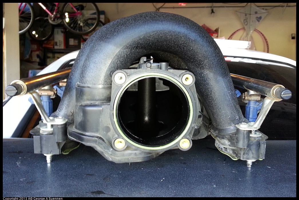
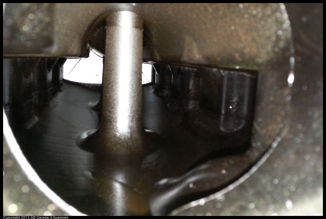
Pulled the intake on my Cayenne S yesterday with Van, to replace the coolant pipes (thanks
Roger for the parts, I appreciate the fine support we get from our 928 venders) and it's a interesting looking part.
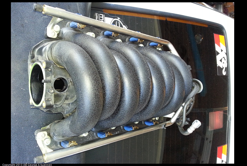
Something like this might work well on the 928.
George
90 S4 Grand Prix White (Murf #5)
94 GTS 5-Speed Midnight Blue
06 Cayenne S Havanna/Sand Beige (PASM)
http://928.jorj7.com
Roger for the parts, I appreciate the fine support we get from our 928 venders) and it's a interesting looking part.
Something like this might work well on the 928.
George
90 S4 Grand Prix White (Murf #5)
94 GTS 5-Speed Midnight Blue
06 Cayenne S Havanna/Sand Beige (PASM)
http://928.jorj7.com
06-09-2013, 01:45 AM
#147
Addict
Rennlist Member
Rennlist Member
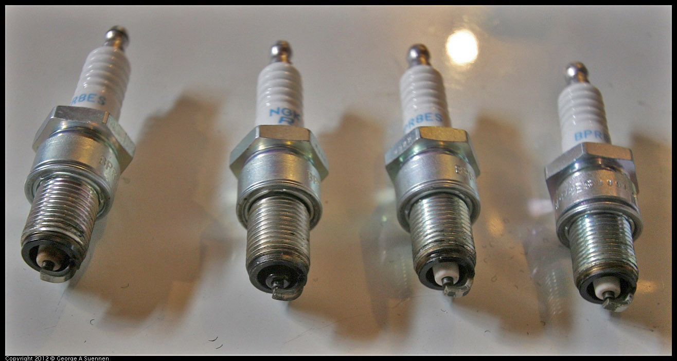
I can't ever recall pulling the spark plugs on a 928 engine and saying "Wow, those two cylinders are richer than the rest!" Has anyone else?
Actually I'm sure I've never seen a difference in "color" in a set of 928 spark plugs, at all.....even on my big horsepower stroker engines which use the stock manifold.....at its flow limits.
I've certainly seen both big and small block Chevy and Ford engines that have different color spark plugs when comparing the outer cylinders to the inner cylinders....and I know that small jet changes will fix this.....so I know that even slight differences in fuel mixture is certainly going to show up on the spark plugs.
Makes me wonder how big of a problem this really is, on a 928 engine....
George
90 S4 Grand Prix White (Murf #5)
94 GTS 5-Speed Midnight Blue
06 Cayenne S Havanna/Sand Beige (PASM)
http://928.jorj7.com
06-09-2013, 07:20 PM
#148
Race Director
George
Your plugs are interesting.....I'd say far left is about perfect, maybe a touch rich
#2 is FAT silly fat......way too much fuel
3 looks lean to me
4 isn't bad, the best of the group........
I read several articles about "reading" plugs.....what they recommend is getting a jewelers loop (I'm unlucky my wife has one) and looking into the base of the white conductor insulation where it meets the base....that is known as the "fueling" mark...it tells you what your AFR is at high load...of course I don't remember which colors mean what.....but drag race guys have it down to a science
for what its worth....mine all look like #4
06-10-2013, 08:06 AM
#149
Nordschleife Master
Thread Starter
I can read tea leaves, palms, or spark plugs, but the logical explanation for why the second plug from the left looks the way it looks is oil deposits. Can't feel the texture in the picture, of course, but it looks like oil problem. It would be a logical explanation as well since your engine had all sorts of oil control problems before Jim Morton rebuilt it right with his custom ring pack, after which I assume you didn't get spark plugs looking like that anymore.
I don't think these plugs are very informative about the intake manifold air distribution.
Last edited by ptuomov; 06-10-2013 at 08:31 AM.
07-08-2013, 02:26 AM
#150
Pro
This one I can't figure out at all. Basically the computer says "does not compute" and brain risks an aneurysm when trying to understand how would it conceivably be possible that these intake spacers would be worth 10 hp at the top end. Especially if it's an otherwise stock car with the stock ECUs that close the flappy at high rpms. The flappy-closed mode should bring further down any resonance points and help the bottom end and hurt the top. So where did these ten ponies (or maybe unicorns) come from?

These are the results to which I referred in my post of a day ago regarding intake plenum resonance.
.