
S4 intake manifold facts and ideas
 03-13-2014, 03:03 PM
#166
Rennlist Member

I would be amazed if you can simply transplant the V8 manifold but if you can it could well be an interesting breakthrough given the results on Rob's motor.
If the 928 inlet manifold was a roaring success Porsche would logically have retained it but they did not. Latest generation V8's seem to have gone down this inverted tube loop.
Doubt I will be pulling the manifold on my turbo S anytime soon but look forward to reading about where you get to on this one.
Regards
Fred
 03-14-2014, 05:30 AM
#167
Instructor
Join Date: Oct 2005
Location: Finland
Posts: 137
Likes: 0
Received 0 Likes
on
0 Posts
Tuomo ..
I started to look throttlebody and found that driver side turn to plenum was more tight than passenger side. Actually I felt that it must be really bad for flow.
So, I started to work with driver side first, then realized that I need to work for passenger side as well as I was able to
smoothen the flow path quite a much on driver side. After some work on both sides, I measured the flow difference and found that it really helped.
Also, found that both sides benefits the work quite a same amount.
Actually I reduced the OD of some of the bellmouths and shortened few mm the 5 & 8 bellmouths. There is enough material on those to modify them.
I think that spacers may be good to get some more space between 5 & 8 bellmouths and side plate, but haven't got them in hand during that time.
Perhaps testing those in future.. I you look carefully, you'll find that I tried to separate the bellmouth edges from walls as the air speed close the wall is zero.
If bellmouth is touching the wall, the velocity profile inside tube entry is not balanced and this is no good for flow itself.
Adding material behind the bellmotuh will work as well. However, I noticed that at beginning the #2 was flowing the best, but after working with throttlebody the #3 started to flow even better.
You can see that #3 is reduced evn more than #2. I came to a conclusion that because the #3 is close the air input(oval tube), it must be the best flowing for that reason.
This is basically the same thing as any other plenum and tubes, closer the intake tube is to input of the plenum, better it will usually flow..
Check also the #1 & #4, they are reduced quite a lot even they aren't that straight.
Sometimes you just need to trust on what the flowbench is saying to you and try to understand later what actually has happened.
I filled the cavities since I made too much putty one time.. Seriously, I was thinking they make turbulence, but perhaps that was wasting of time of epoxy.
I don't think making plenum that bit smaller really makes any change to resonance peak, but don't know this for sure.
You can see that the project was quite a complex, but it was also interesting and I learned a lot from flow dynamics. There are many ways to reduce restrictions from our intake.
I'm not saying I did everything right, surely it was also based on trial and error method.
03-19-2014, 05:29 AM
#169
Instructor
Join Date: Oct 2005
Location: Finland
Posts: 137
Likes: 0
Received 0 Likes
on
0 Posts
No I didn't since last summer I drove the car with retarded ignition as intake tubes were still unbalanced and too much knocking on some of the cylinders.
Will do it at upcoming driving season. However, my testing with real life engine and flowbench has shown that it works noticeably better than before.
The gains also depends on which engine it will be used, the stroker may be able to benefit more than "little" 5L. The 5L "air pump" isn't strong enough to draw that much air as others.
The flow on each cylinder and intake tube is not static steady flow in real life, it's rather series of pulses. If all the eight cylinders shares one plenum,
the flow through throttle plate is more steady and there is less pressure drop through TP. That said, single plenum is more efficient than dual plenums in our V8 engines, IIRC something like 97%.
Having dual plenums with spearate throttle plates, the efficiency of plenum is less than 90% and so on. More cylinders, gives higher pulse frequency which gives more steady flow through throttle plate.
This is the reason of why the ITBs are the worst efficient and therefore the diameter is relative large on those to compensate the effifiency drop.
Our intake is kind of mixture of single and dual plenums, the throttle body is shared, but plenums still have separate flow paths to each of them(oval tube).
This all means that steady state flow doesn't necessary tell of how well the intake is working, it still gives an idea of flow balance across intake tubes and plenums.
I would rather refer to flow restriction and pressure lost. By removing the restrictions from intake path results less pressure drops in live engine and the result is better cylinder filling.
Therefore the flowbench steady state flow increase will not necessary tell all of how succesfull is your flow path modification..
Don't know if I was able to explain this clearly as my english skills prevents it sometimes. Also, these are just my only conclusions, as being engineer I need to always try to find some sense of these things
Ps. depending on your HP goal, the 74mm throttle plate may be too little. The local 911 turbo guys told me that optimal hp for 74mm is around 750hp. Some of them has been used it up to 1000hp,
but pressure loss must be huge and higher boost may be needed to compensate this.
03-19-2014, 11:36 AM
#170
Rennlist Member
On the Cayenne front, not sure that is going to happen. An adapter is possible, but injector placement is lousy. Also, the necessary height of the adapter to get a decent transition would place it to high to clear the hood.
Only way this would work is with some cnc-milling to remove the original flanges, and use silicone couplers to a machined base.
It was worth a look.
Only way this would work is with some cnc-milling to remove the original flanges, and use silicone couplers to a machined base.
It was worth a look.
03-19-2014, 12:01 PM
#171
Nordschleife Master
Thread Starter
A big block Chevy or Mopar port injection manifold is way more likely to fit as a starting point, given the deck height and bore spacing. The modern V8's are tiny small blocks compared to the 928.
03-19-2014, 01:13 PM
#172
Rennlist Member
Join Date: Oct 2009
Location: Michigan... Grand Rapids
Posts: 758
Likes: 0
Received 2 Likes
on
1 Post
Yeah it was worth a look, but oh well. A Chevy would not work as the outlets sit on a V shape, not flat. I think the closest would be a Ford 5.4 like this. It also has outlets that are about the correct shape
03-19-2014, 01:35 PM
#173
Nordschleife Master
Thread Starter
A couple of thoughts:
- I think it's waste of time trying to modify plastic manifolds. One needs to start with a metal manifold.
- Since an adapter is needed anyway, the shape of the runner opening is not critical
- The deck height (or more accurately, the distance of the ports between banks) and the bore spacing have to be very close. These basic dimensions rule out modular Ford, Chevy small block, etc.
For an intake manifold project, I would look for an aftermarket cast forced induction manifold for an American big block engine. Everything else is likely a total waste of time and money. and even those most certainly are once the cost of fabricating an adapter is taken into account.
03-19-2014, 05:29 PM
#174
Rennlist Member
I don't think that intake manifolds are going to happen for our cars. Just not enough interest to justify the tooling expense for anything production. Machining is too expensive for one... Oh well, maybe when the price of SLS comes down we can make them.
03-19-2014, 09:24 PM
#175
Instructor

Join Date: Feb 2005
Posts: 209
Likes: 0
Received 0 Likes
on
0 Posts
There's always the sheet metal route for $2-3k for those that want a custom manifold through someone like Hogans. These cars are too low volume and everyone is doing something different with their cars. There will never be a one size fits all aftermarket manifold.
03-20-2014, 10:21 PM
#176
Nordschleife Master
Thread Starter
It would be great if a custom "sheetmetal" intake manifold fabricator would make us a well performing single plenum manifold for usd 3,000. I'm not sure you can get one done, even if you order three, for that unit price.t
03-20-2014, 11:48 PM
#177
Instructor
Join Date: Feb 2005
Posts: 209
Likes: 0
Received 0 Likes
on
0 Posts
Hogans will build a one off LS style manifold for around $3k if you provide them all the dimensions and measurements. How well it would perform on a 5 liter 32v engine is unknown. They seem to work pretty well on LS7's.
04-12-2014, 12:59 PM
#178
Nordschleife Master
Thread Starter
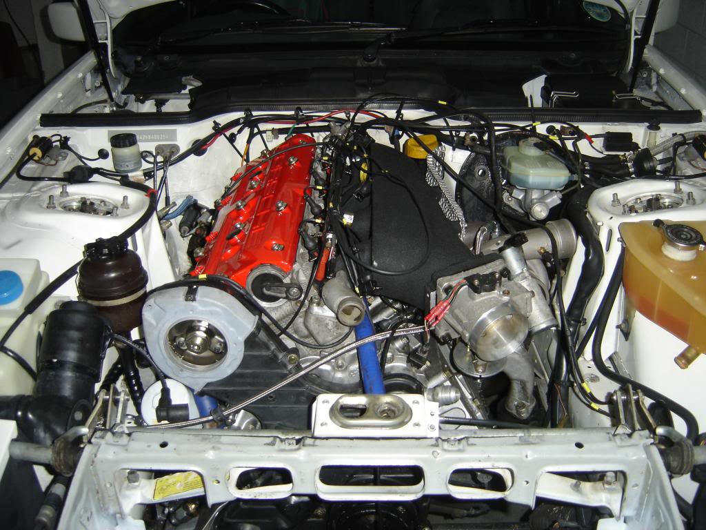
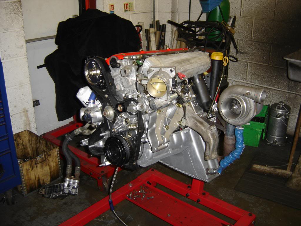
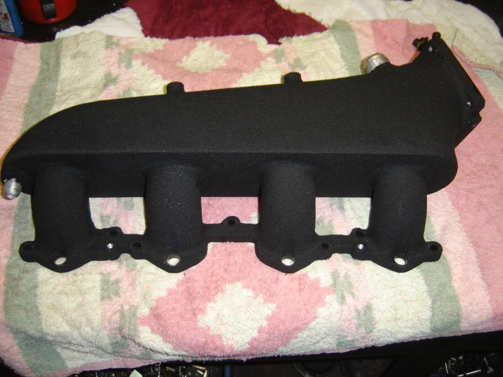
Here's an interesting manifold for a turbocharged 944 s2 with 16V head and 3.0L displacement. It's fabricated from a stock 944 S2 manifold and an aftermarket plenum cover originally meant for a Toyota (I think). What's remarkable about the manifold is that, once you factor out the impact of boost, it produces an almost perfectly flat normally aspirated torque curve between 2500 and 7000 rpm. I don't quite understand how the builder did it, maybe he's setting the Helmholtz peaks around the natural camshaft peak?
https://rennlist.com/forums/944-turb...o-project.html
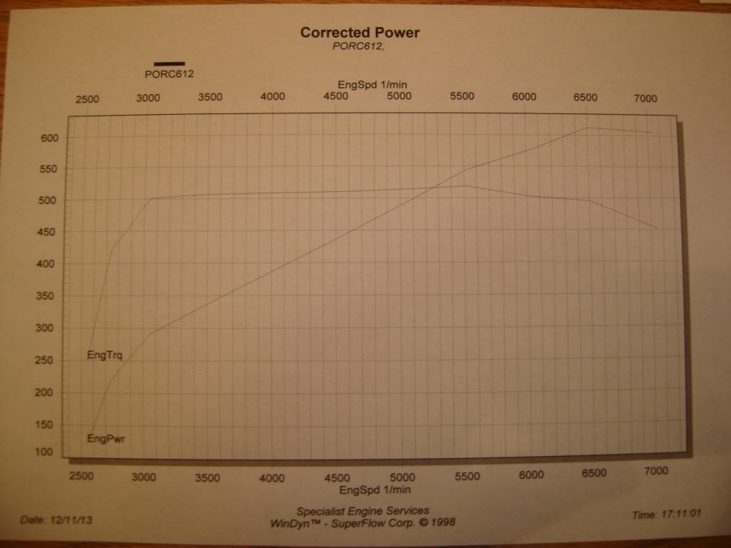
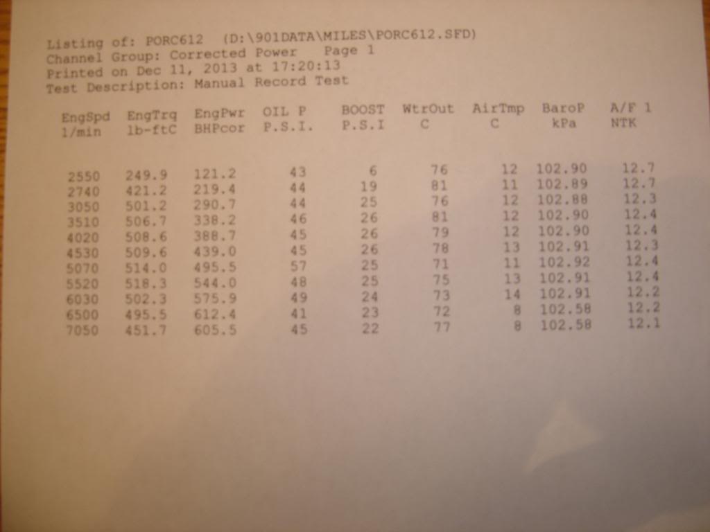
rpm, TT3 torque, TT3 boost psi, Torque per abs psi, TT3 torque rescaled to ambient, Stock 16v 3L torque
2550 250 6 12.1 178 195
2740 421 19 12.5 184 197
3050 501 25 12.6 186 200
3510 507 26 12.5 183 206
4020 509 26 12.5 184 207
4530 510 26 12.5 184 206
5070 514 25 12.9 190 205
5520 518 25 13.0 192 198
6030 502 24 13.0 191 182
6500 495 23 13.1 193 160
7050 451 22 12.3 181 130
https://rennlist.com/forums/944-turb...o-project.html
rpm, TT3 torque, TT3 boost psi, Torque per abs psi, TT3 torque rescaled to ambient, Stock 16v 3L torque
2550 250 6 12.1 178 195
2740 421 19 12.5 184 197
3050 501 25 12.6 186 200
3510 507 26 12.5 183 206
4020 509 26 12.5 184 207
4530 510 26 12.5 184 206
5070 514 25 12.9 190 205
5520 518 25 13.0 192 198
6030 502 24 13.0 191 182
6500 495 23 13.1 193 160
7050 451 22 12.3 181 130
04-17-2014, 06:06 AM
#179
I don't have time to read this whole thread but just in case Simos didn't know, the Nascar engine builders believe that the evening of airflow between the runners is worth between 5 to 20 HP. They do the airflow adjustment by the camshaft. That is every cylinder has its own profile.
Here's a comparison of an unmodified intake with Simo's intake:
Attachment 814508
Attachment 814510
Attachment 814509
Attachment 814511
The long center runners have been constrained with something (I am guessing epoxy aluminum putty but I don't rally know). The short end runners have their bellmouths opened up.
Questions to Simo:
- Did adding the restrictors to some runners and enlarging others to ellipses equalize the steady state flow?
- Are you measuring the steady state flow with or without the plenum covers on? If you did both, does the cover further exacerbate the flow differences between runners?
- How much more will the intake manifold, stock or modified, flow with the lower throttle body element removed vs. thru it?
02-01-2015, 02:27 PM
#180
Nordschleife Master
Thread Starter
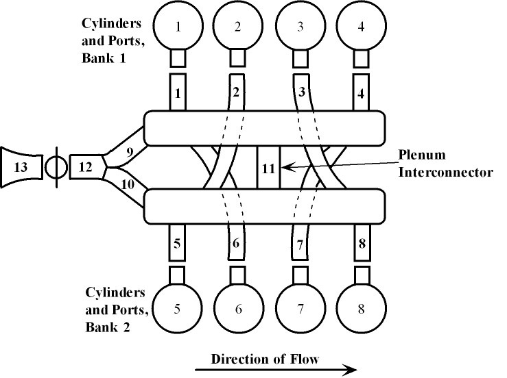
My dual pipe, dual chamber Helmholtz resonator spreadsheet gave some directional info, but ultimately it's turned out to be unsatisfactory. Subsequently to writing that spreadsheet, I've acquired a fairly comprehensive 1D simulation software for four-stroke engines. This software is a step up from packages like Engine Analyzer Pro 3.9 or Dynomation 5. In particular, the software package allows one to construct inlet manifolds from pipe section and plenum legos and it models the interaction of all cylinders explicitly. The designer of the software is helping me with programming the stock 1987 S4 engine, and it may become one of the example engines in the software package. I would guesstimate that this level of simulation technology matches or exceeds what Porsche engineers had available in the mid 1980's.
1D simulation technology by its nature will need some flow bench experiment data as input and some pressure trace data to validate the output. I anticipate that down the road I'll have access to both, although the pressure trace equipment is harder to install than I anticipated. I will also have to measure, estimate, and/or assume a friction model, which I haven't done yet.
Here's a sample output, pretty much out of the box.
The inlet is configured as a front feed, but it doesn't make any difference in the model whether it's front feed or rear feed.
Ignore the torque scale since there's no friction model yet. Focus on the shape, which will with friction model rotate slightly clockwise. I think it's a pretty good first effort.
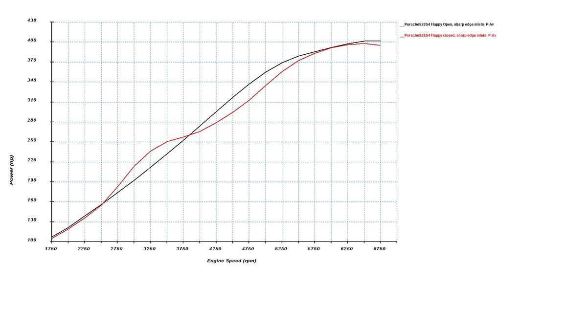
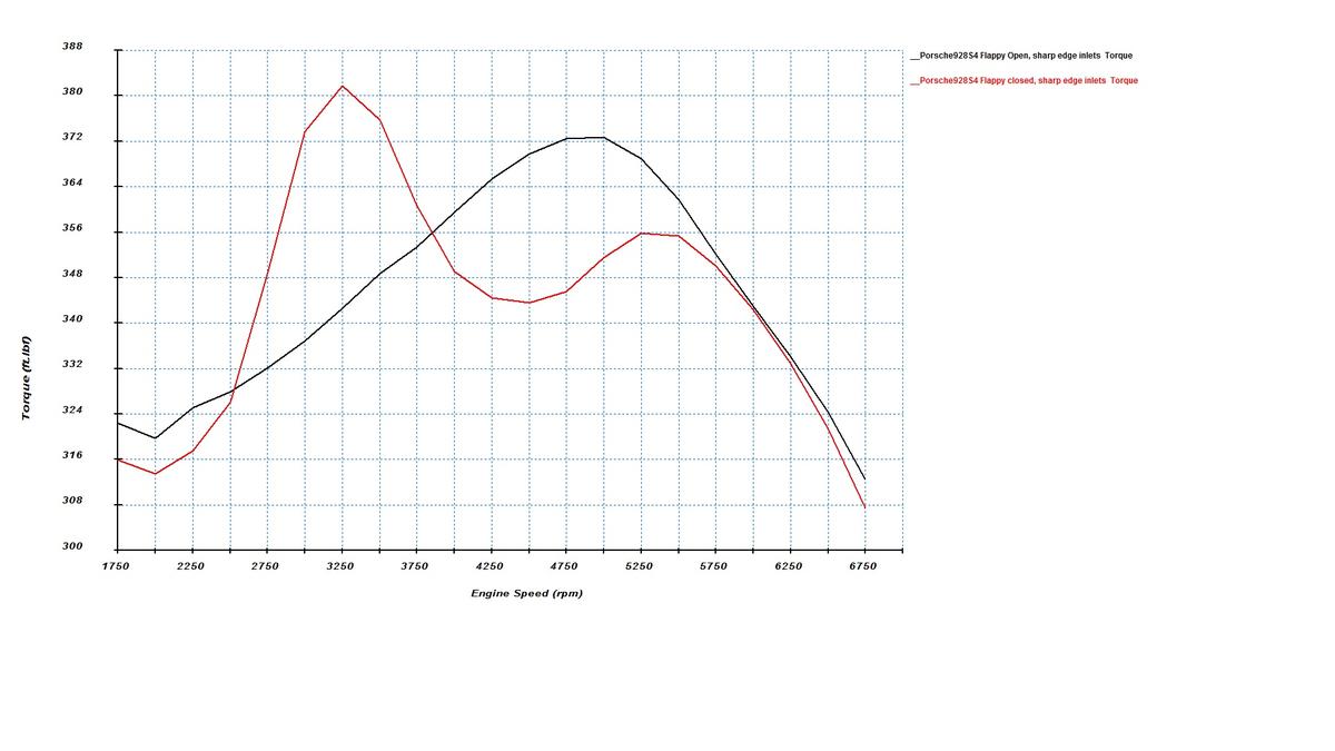
The biggest challenge is with modeling the lower cast throttle body element. The model is sensitive to the secondary pipe length and it's not obvious how that component works.
Even with this better software program, it's not "cut and dry". There's still a fair amount of "cut and try" left... Still, I think this is a step forward in understanding how the stock inlet manifold works and will allow for a somewhat accurate directional predictions about what things such as plenum spacers will do.
1D simulation technology by its nature will need some flow bench experiment data as input and some pressure trace data to validate the output. I anticipate that down the road I'll have access to both, although the pressure trace equipment is harder to install than I anticipated. I will also have to measure, estimate, and/or assume a friction model, which I haven't done yet.
Here's a sample output, pretty much out of the box.
The inlet is configured as a front feed, but it doesn't make any difference in the model whether it's front feed or rear feed.
Ignore the torque scale since there's no friction model yet. Focus on the shape, which will with friction model rotate slightly clockwise. I think it's a pretty good first effort.
The biggest challenge is with modeling the lower cast throttle body element. The model is sensitive to the secondary pipe length and it's not obvious how that component works.
Even with this better software program, it's not "cut and dry". There's still a fair amount of "cut and try" left... Still, I think this is a step forward in understanding how the stock inlet manifold works and will allow for a somewhat accurate directional predictions about what things such as plenum spacers will do.