When you click on links to various merchants on this site and make a purchase, this can result in this site earning a commission. Affiliate programs and affiliations include, but are not limited to, the eBay Partner Network.
Definitely bigger ones with those compression numbers, and/or running them retarded.
Elgin 65-6 lobes with 114 LSA installed straight up. So, yes, they are bigger than stock. Plus, the static compression ratio is 8.6:1. 15-17 Hg idle vacuum, depending on the day.
Those cams are really, really well matched for the 5.0L engine with stock intake manifold. They allow us to run constant boost and get a flat torque curve.
This is the last pump gas 93 octane run. The torque curve looks the way I want it to look, except the engine can�t be run up to high enough rpms. I believe that, with that right boost settings, the cams would carry the engine to 8000 rpm redline just fine. It would also be interesting to see how the stock S4 intake manifold works up there in the higher rpms.
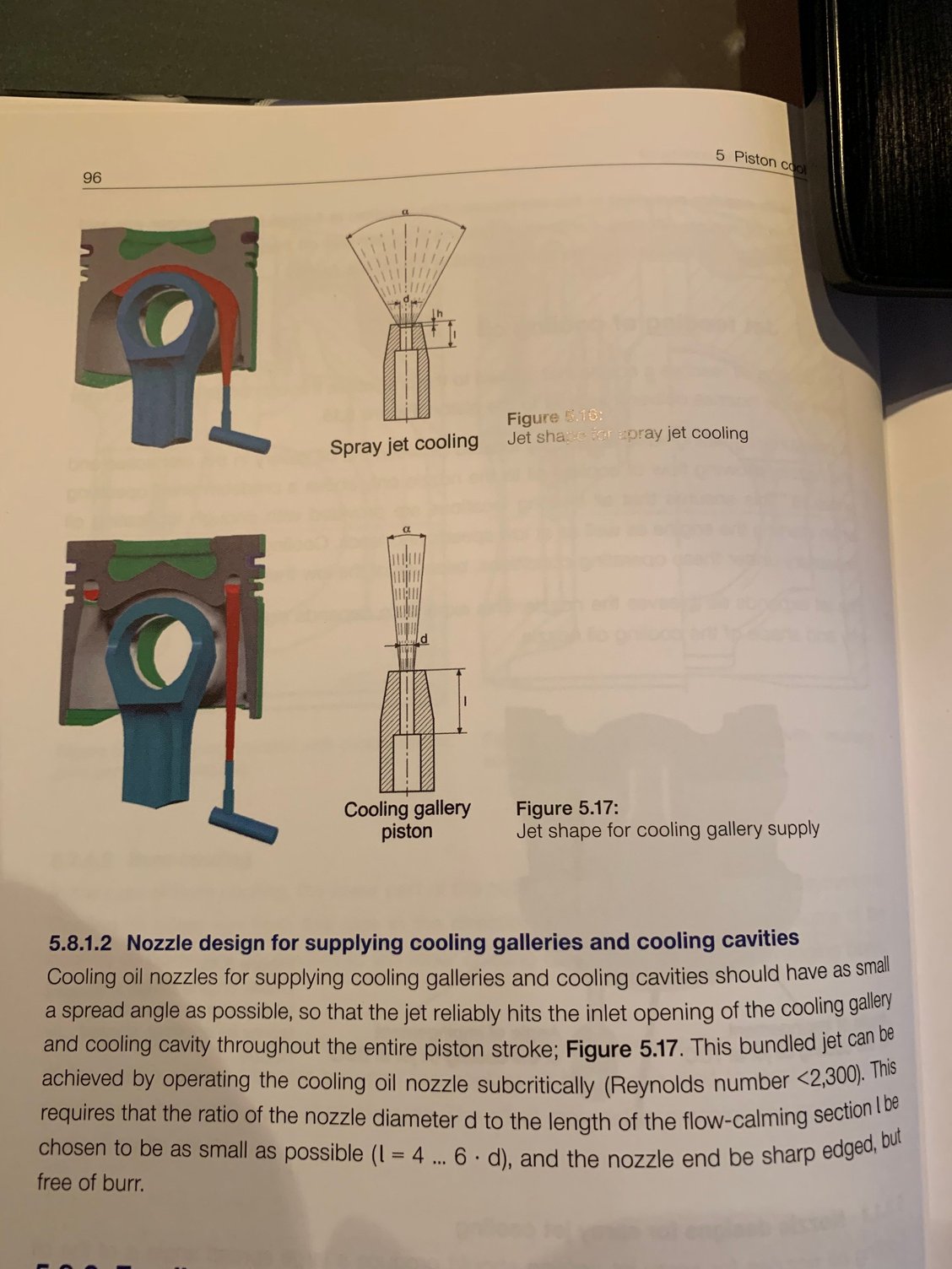
Next up is a piston oil cooling jet aka �squirter� spray pattern test. The result may conceivably influence the correct piston design for the higher rpm engine:
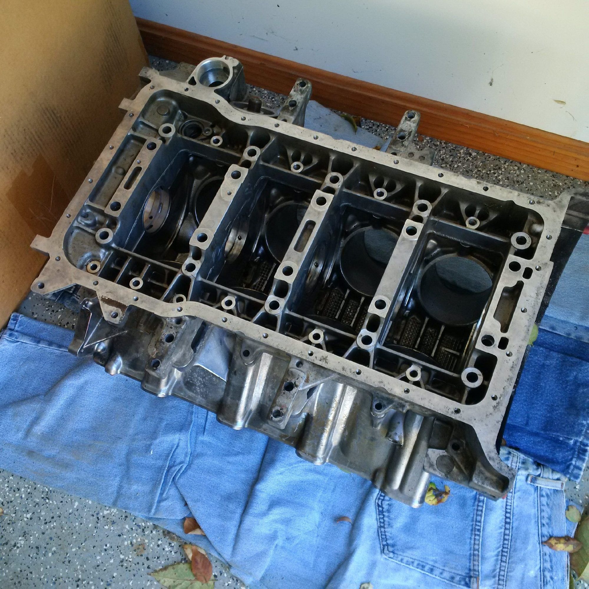
Since we hit the transmission limits on torque and we know the stock S4 bottom end rpm limits, the next logical thing is to build three short blocks that can take both boost and higher rpms.
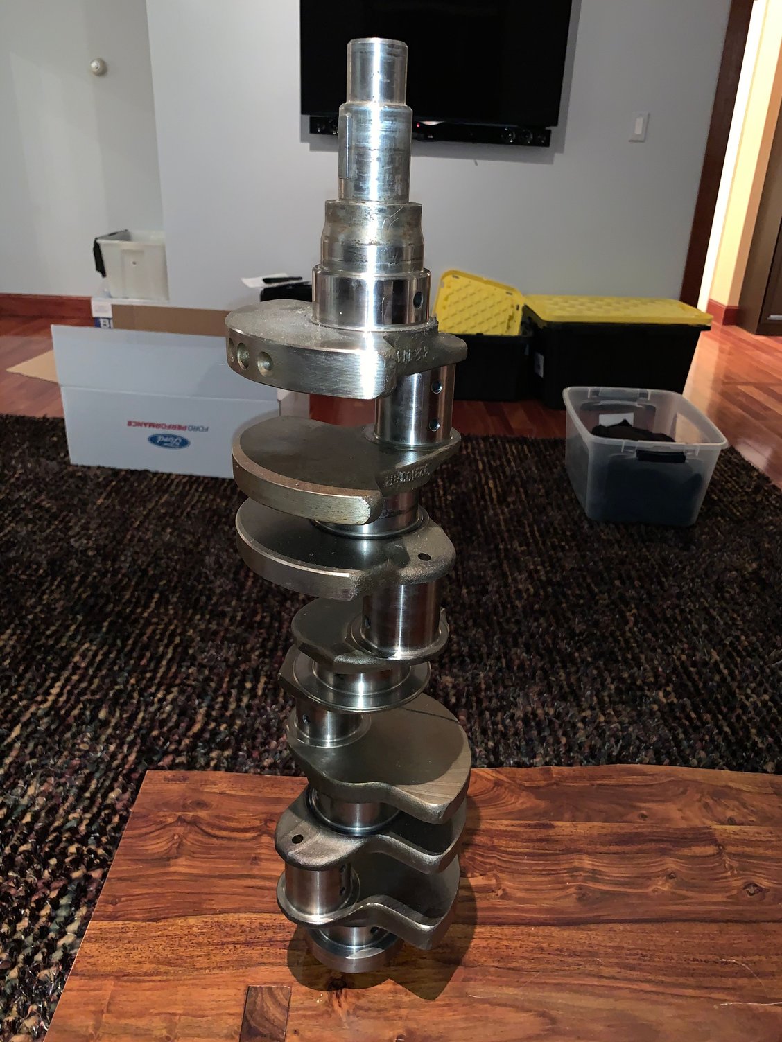
Since the S4 crankshaft is excellent overall, we are retaining that with minor modifications, which include reshaping the middle counterweights, reducing the sweep radius of all counterweights, and adding some oil passages for the scenario in which the main block feed passage receives a lot of air in addition to oil. The pistons and rods need to be changed, however, as the overall
excellent �87 stock S4 pieces are too heavy.
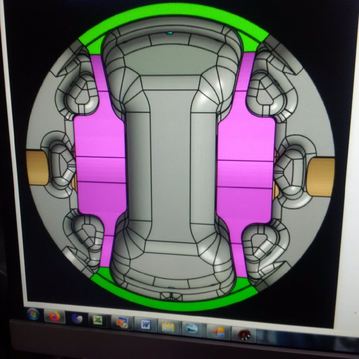
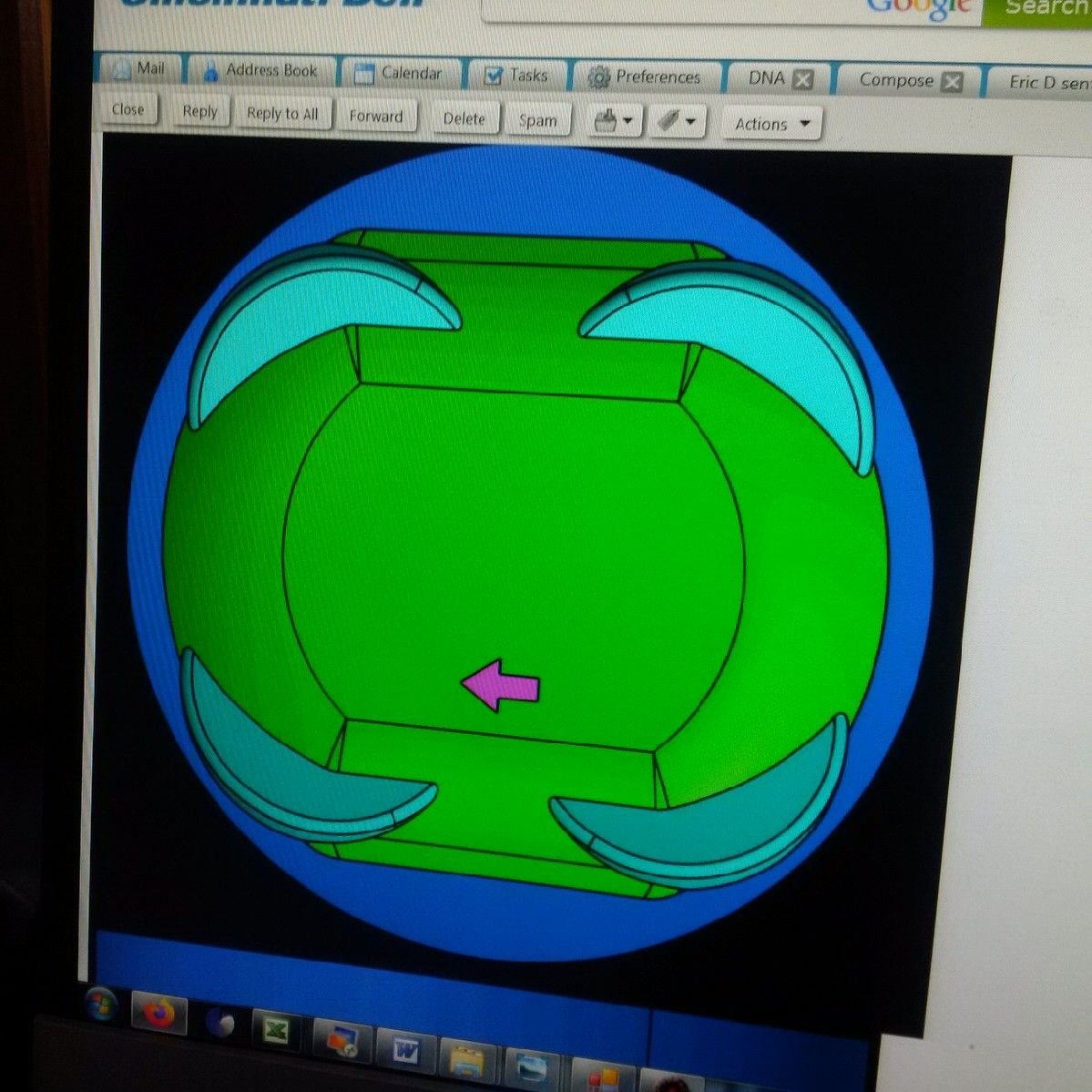
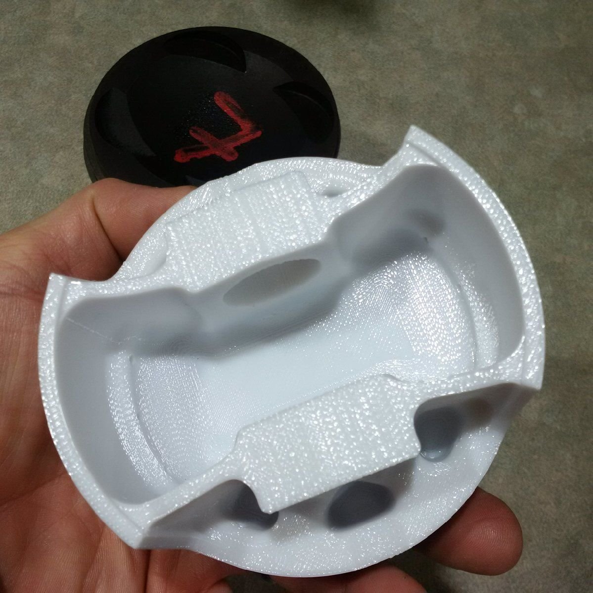
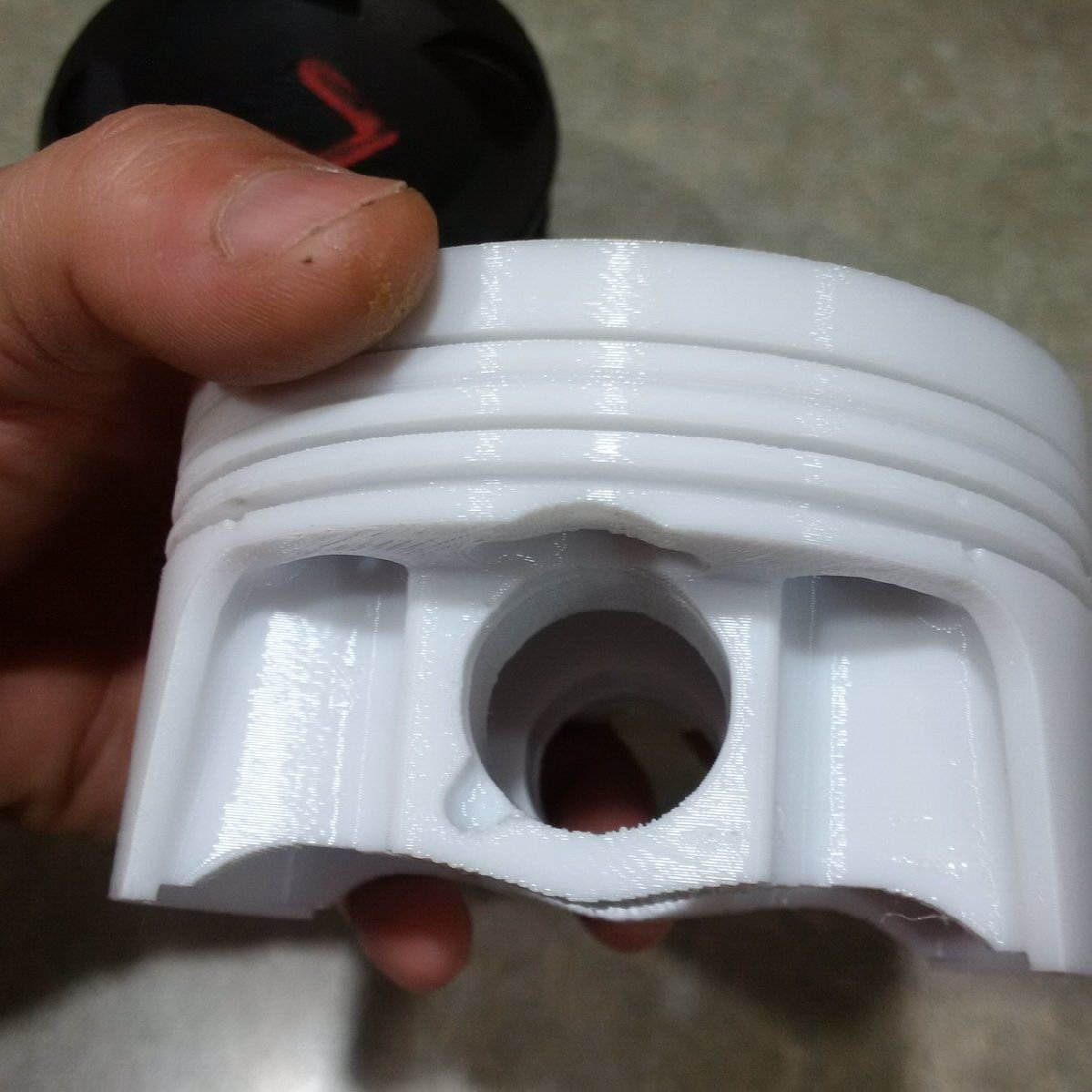
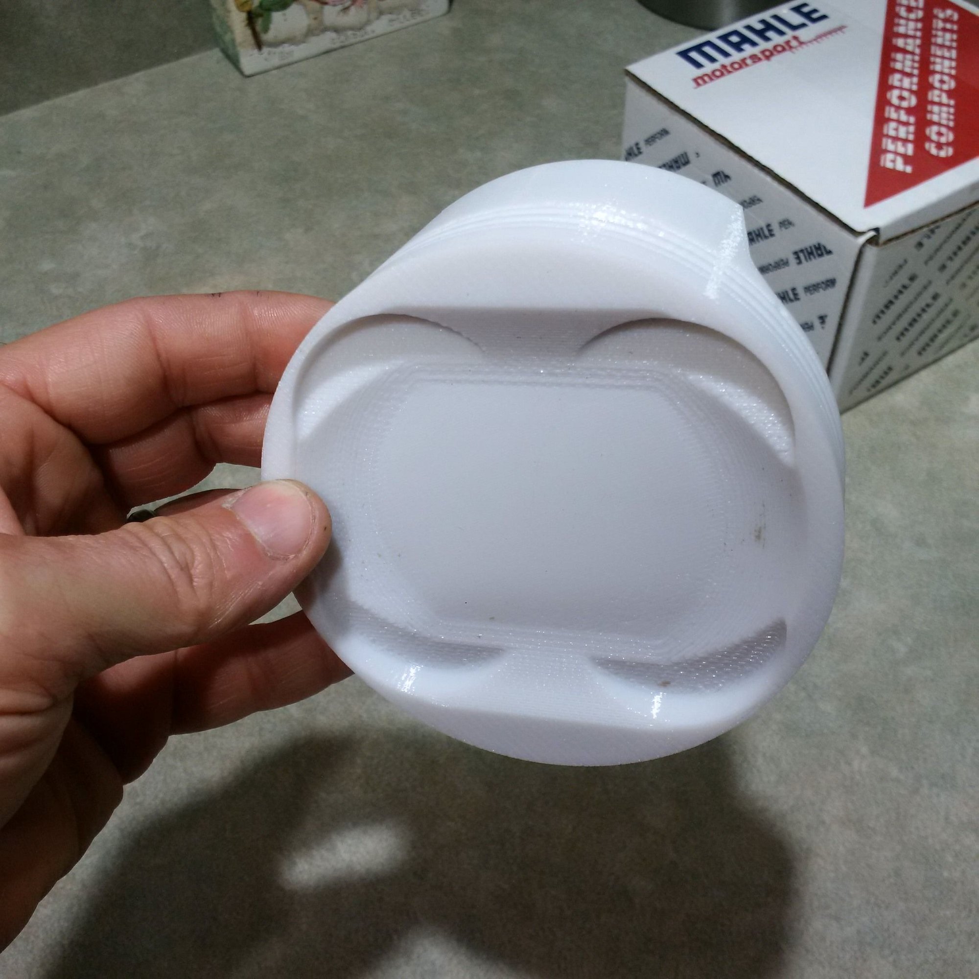
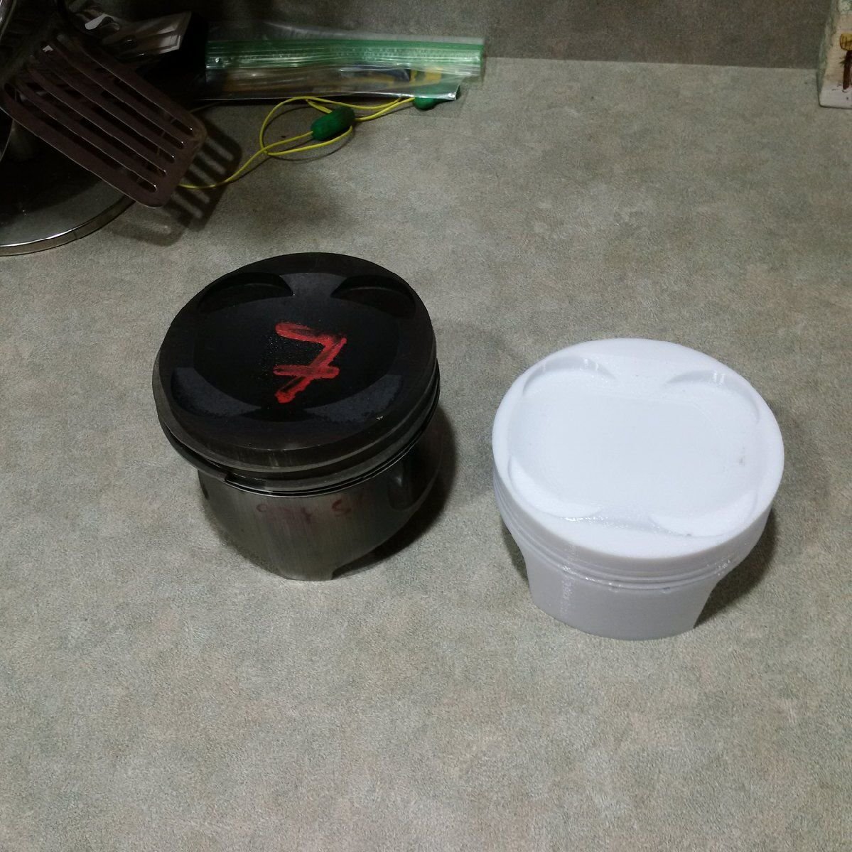
Here are some photos of a 100mm mock-up piston that John is planning to use in the next three short blocks.
We�ve spent some time understanding the 928 bottom end geometry.
An interesting engine related to bottom end geometry and turbo cylinder pressures is �even fire� turbo Buick 90-degree V6. The bottom end is weird in that the rod and bearing are offset by about 0.120�-0.125� or 3mm to the side of the piston. This unusual geometry is good for 750hp, which would mean about 1000hp in a V8 setup. This is with a rod that is about 5mm shorter than the 150mm 928 rod. You can read more about it at https://turbobuick.com/threads/on-ce...tage-2.323208/. My conclusion is that with power levels under 1000hp one shouldn�t worry too much about 1-2mm play of the piston relative to rod. On center is better than off center, of course, but this is a situation in which exactly centered can slightly offset makes no difference. Big offsets start getting harder and harder on the components, though.
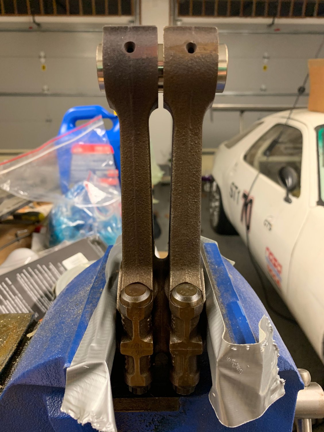
That said, I played around with some later stock cast rods and measured the rod big end offset parameters to best of my ability.
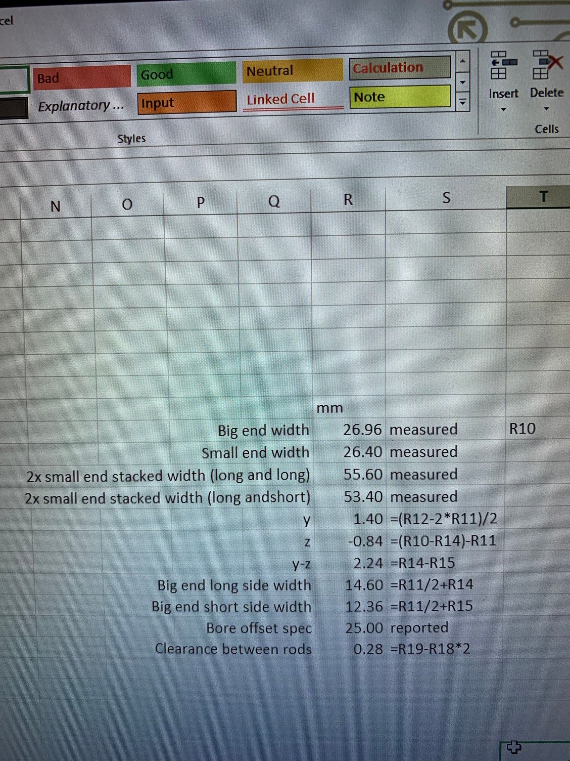
First, I stacked and clamped two rods from the big ends with the long cheeks on the center. Then, I measured the distance between the two small end outer edges. There�s a large air gap between the two small ends. The measurement result averaged about 55.60mm. This is not a super precise measurement, but close enough to government work.
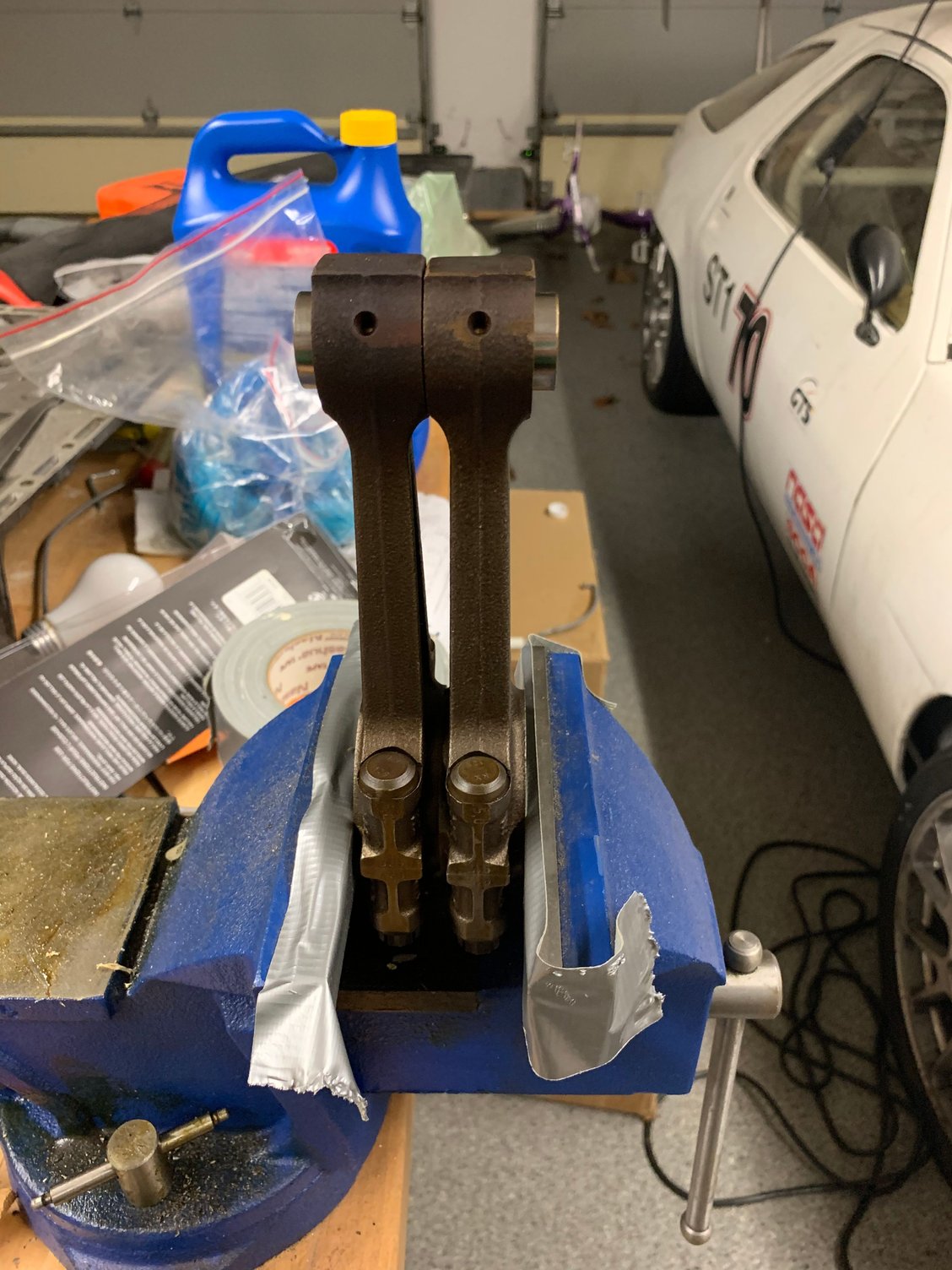
Then I flipped one rod so the two rods are now "spooning". This leaves a small air gap between the small ends. Again, I measured the span. The results averaged 53.40mm.
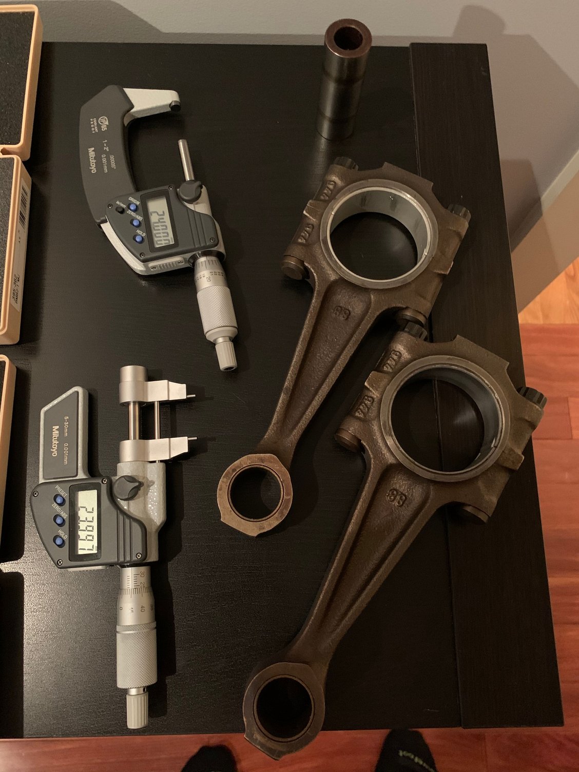
Then I measured the small ends and big ends again separately. The big end width averages 26.96mm and the small end width averages 26.40mm.
Then I did some math, two equations and two unknowns. Variable y is the long cheek extension from the small end plane. The result is +1.40mm. Variable z is the short cheek extension from the small end plane. The result is a negative number at -0.84mm.
With these numbers, you get long cheek big end width from the beam centerline at 14.60mm and the short cheek width from the beam centerline at 12.36mm. If we take the reported bore offset to be nominal 25mm, we get 0.28mm running center clearance between rods when they are exactly centered under the pistons, which is reasonable. The journal length for one crank is 54.10mm, with the factory maximum tolerance at 54.13mm. There�s measurement errors there for sure, but I think these numbers are at least indicative.
As far as I can tell, everything is consistent with nominal design parameters of 54mm crankshaft journal length, 52mm crankshaft journal diameter, 12.5mm short center cheek, 14.5mm long side cheek, and 25mm bore offset, plus then tolerances and clearances around that.
Since the we�re planning to run more rpms with lighter components, it isn�t �optimal� to run the insanely long 24mm stock bearings. Sure, they could work but they are not the best choice for our planned loads, oil flow, and/and bearing speeds.
So that plan involves switching from soft but long 24mm bearings to shorter but harder 19.6mm bearings. With shorter bearings, the oil hole location and diameter needs to be checked. The oil hole is 9.5mm diameter, so it�s big but I can�t see it causing any issues given that there�s over 10mm of support length even right at the hole. The journal diameter is 52mm and the bearing clearances on the tight side.
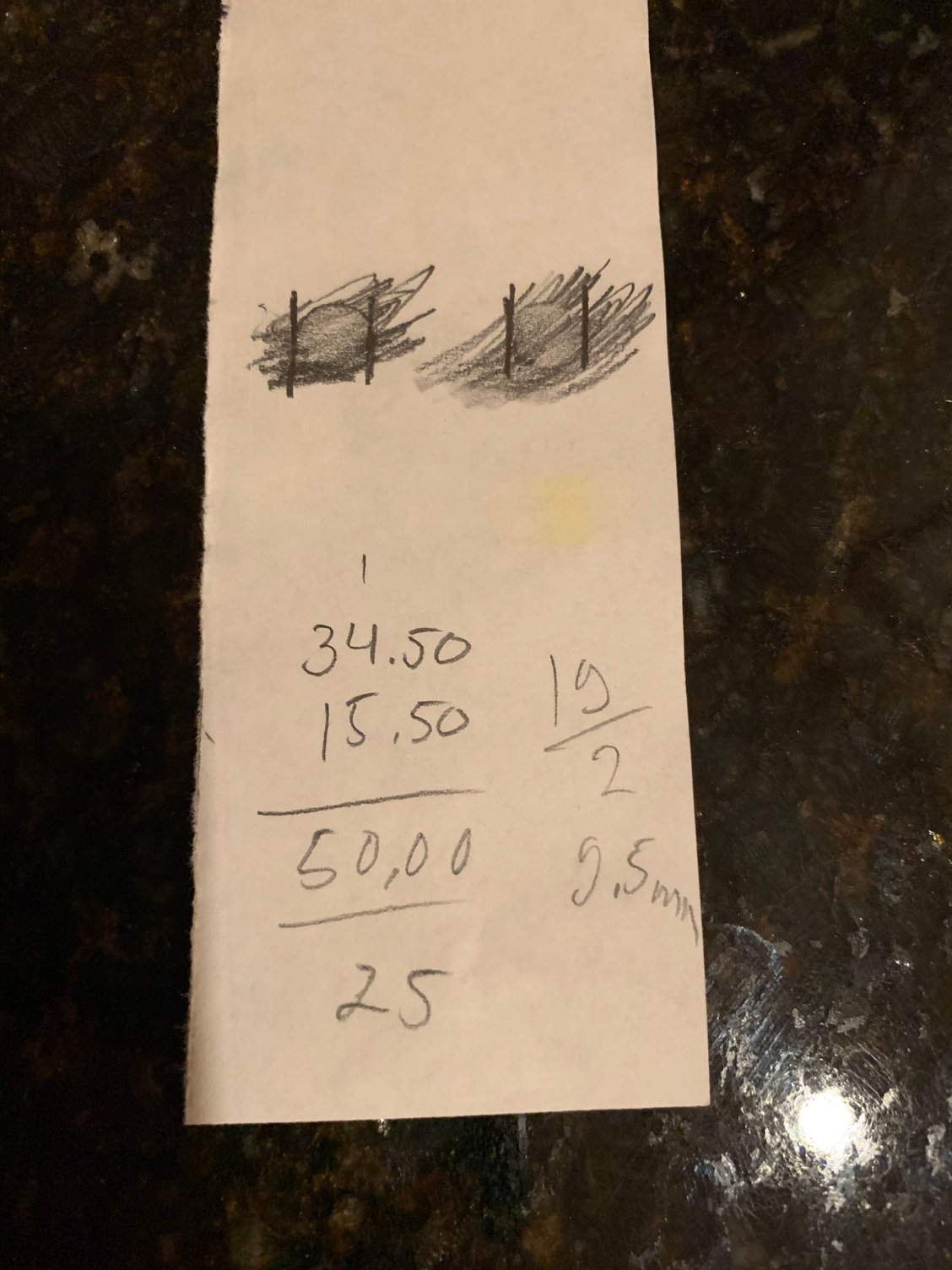
As a fun project, I was teaching my 11 year old daughter Sonja to take measurements of parts. Sonja and I took the oil hole distance measurements from a very awkward measurement location on one relatively recent model crankshaft using a �ghetto� technique. I had her take an imprint with pencil and paper and then we measured the oil hole width and spacing from the imprint. Outside edges 34.5mm, inside edges 15.5mm, for a center to center distance of 25.0mm. The hole diameter 9.5mm. All checks out for 25mm bore offset block.
Since we can fit a 24mm wrist pin in these Mahle piston forgings, we are planning to go with those. There are bending considerations and shearing considerations with the wrist pin. If the wrist pin clearance between the rod small end and piston pin boss is very small, the shearing consideration is relatively more important. If that gap is large, the bending consideration is relatively more important.
The end result is design with about 1mm of clearance on both sides between the pin bosses and the rod small end. Also, a short but massively thick 5.5mm wall, 24mm diameter steel pin.
There�s also the question of pin to rod small end clearance. We�ll be in a fortunate position with a stiff, large diameter pin and wide rod big end. This means that there�s relatively little bending and flex. Everything points to wrist pin oil clearance of 0.08-0.1% of the wrist pin diameter.
By the way, it�s difficult to improve on the stock 24mm pins given the design. Even used, them all in my pile measure +/- 0.004mm (!) from the spec mid point.
Here are some more specifics on the shorter bearings.
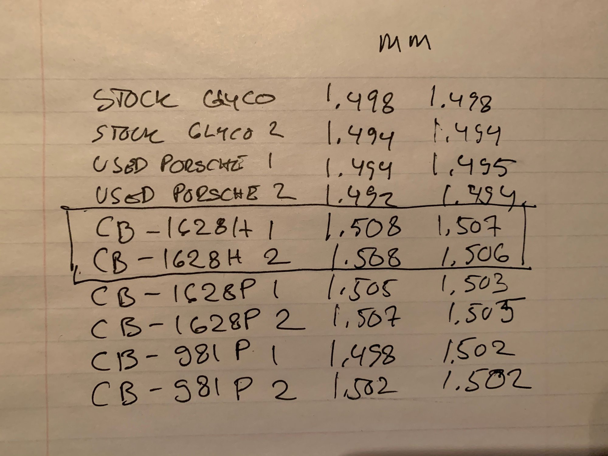
Earlirt this month, I measured various bearing shells after everything warmed up to 70 degrees. The attached photo has all the measurements. This is with a ball anvil mic which is not perfect for this job, cylinder anvil would be perfect. Ball anvil is still pretty good if you�re really gentle.
New Glycos average 1.496mm
Used Porsche bearings average 1.493mm
Supra Clevite CB-1628H bearings average 1.507mm.
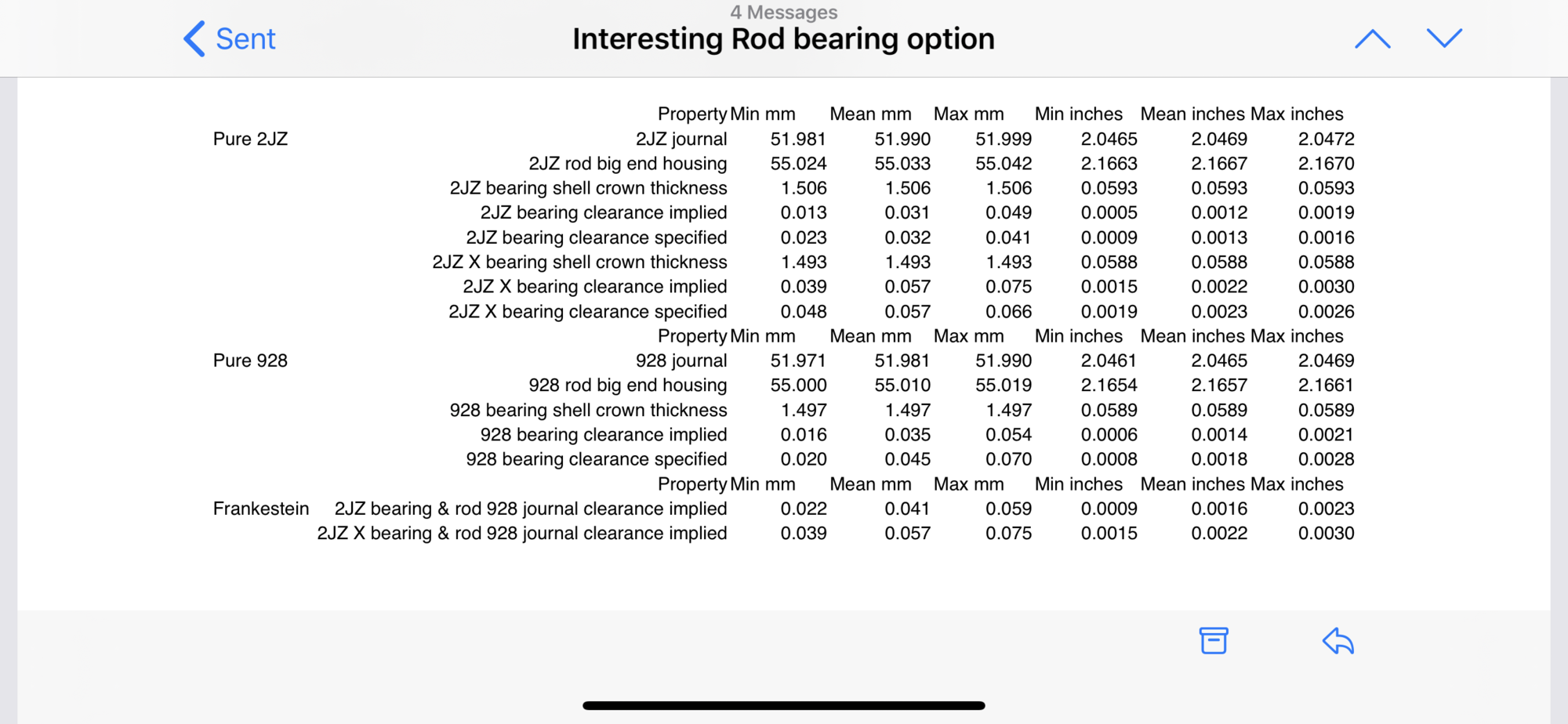
One could run the Clevite CB-1628H or HX bearings on reconditioned stock rods, too. However, they really start making sense to me when one moves the redline up from the stock 6700 rpm redline. Those bearings run all day and all night in high-boost Toyota Supra 2JZ-GTEs that go over 8000 rpm with high boost and longer than 928 stroke. Our piston and rod weights will come in under the 2JZ-GTE values, too.
Saw one of the more tastefully modified 911s on the way to heating the old-school sauna:
In the meanwhile, I�ve been thinking about the S4/GT crankshaft that is a very high quality piece as far as crankshafts go.
People are often very critical of the oil passage scheme, in my opinion it works perfectly as long as the pickup doesn�t suck air, even at high rpms. At high rpms, the crankshaft just needs enough oil pressure at the mains.
When the pickup sucks air, the air gets separated into main #2 and from there to 2/6 rod. The �Taylor� drilling of the crank connects all the passages between main and rod journals and helps distribute the air more evenly when the pickup sucks air. Girdle modifications at the galley to main #2 also help even the air distribution. I think both are useful crutches, even though the real problem is the pickup sucking air.
For these two short blocks, the bobweight will go down a lot. This leads to the question of how to lighten the crankshaft. The first method is to cut the center 3 and 6 counterweights to better align behind the 2/6 and 3/7 for journals, which should reduce the main bearing loads. The second method is to reduce the radius if all the counterweights on a lathe. This has the benefit of keeping rotating components further from oil and helping the crankcase gas flows. Scratching my head on how to trade off the two.
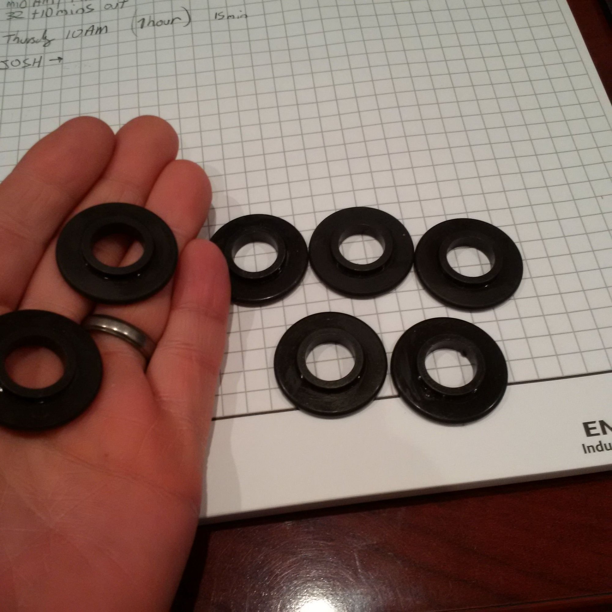
John had some spring bases manufactured from some specific steel alloy (don�t know the details) and they have ban hardened as well. These produce the ideal fit for the PAC-1223 beehives.
I can tell you that after forty years of letting the manufacturing base to hollow out, whoever is left in the US manufacturing sector is currently drowning in work. Really hard to get small series of anything made quickly!
I can tell you that after forty years of letting the manufacturing base to hollow out, whoever is left in the US manufacturing sector is currently drowning in work. Really hard to get small series of anything made quickly!


 10-04-2019, 05:59 PM