When you click on links to various merchants on this site and make a purchase, this can result in this site earning a commission. Affiliate programs and affiliations include, but are not limited to, the eBay Partner Network.
As far as the high-rpm knock problem goes, it's not that 1&6 fill better with new air. They don't. It's that the hot exhaust gas doesn't get out of the cylinder because 3&5 blow into the exhaust ports during the valve overlap, and that exhaust gas heats up the new charge such that it knocks. So those cylinders don't really need more fuel, they just need a retarded ignition timing.
For the mid-range rpm knock that is not caused by exhaust but instead by some cylinders having better filling intake runners, fueling and ignition trims both would be useful.
In my case, however, that mid-range imbalance problem isn't nearly as consequential as the high-rpm imbalance problem, so cylinder-specific ignition trim would be a higher priority than cylinder-specific fuel trim.
There is a thread where Todd, the Mad Scientist, hooked up 8 WBO2 to look at this issue. As I recall there was a few points differece between the richest and leanest. But not nearly as bad as a corvette. He abandoned the stock ECU in favor of a more sophisticated controller.
AFAIK, the stock ECU only gives individual ignition trim in a "safety-corrective" manner (i.e. in response to knock) which is not ideal when trying to maximize power. You will likely have to tune to the overall threshold that works across all cylinders (both fuel and ignition) without knock. Just a limitation of the systems that came with the car.
Mike Vance had a switch that allowed one to switch between Maps on the fly (using the coding plug). In that way, one could, in theory, to have a map for cool weather, normal, or "wicked hot" to maximize output based on conditions/fuel/boost, whatever. But you only get 3 options.
There is a thread where Todd, the Mad Scientist, hooked up 8 WBO2 to look at this issue. As I recall there was a few points differece between the richest and leanest. But not nearly as bad as a corvette. He abandoned the stock ECU in favor of a more sophisticated controller.
I am familiar with the data from this particular experiment, as I have the fueling data from that engine/experiment and have spent some time analyzing it. I've merged it with some simulation data, estimated the cylinder specific vol-F numbers, and ended up with slightly different conclusions.
First, just to figure out the magnitudes, the differences are not AFR points, they are percentage points. Second, while the intake manifold causes some of the differences in fueling, my conclusion from the data was that exhaust blowdown interference is as important if not more important factor causing vol-F differences. Third, the tendency to knock at high rpms is caused by the heat from residual exhaust gas and not by the high vol-F.
Here's my estimated impact of 180-degree and 90-degree exhaust blowdown interference on vol-F at each rpm. At 6000 rpm and above, the 90-degree exhaust blowdown interference victims are down about -6% in vol-F.
Controlling for the exhaust blowdown interference, the long runners generally fill better, but the difference isn't huge:
RPM 2000 2500 3000 3250 3500 3750 4000 5000 5500 6000 7200
Short -0.8 -0.1 -0.4 -0.1 0.3 -1.4 -2.0 -1.0 -1.9 -1.3 -1.1
Long 0.8 0.1 0.4 0.1 -0.3 1.4 2.0 1.0 1.9 1.3 1.1
The below table averages the filling for curvy and straight runners. Runners #5 and #8 are classified as curvy while the rest of the runners are classified as straight. This also controls for the exhaust blowdown interference, but not for the runner length:
So the curvy runners start hurting as the flow rates increase.
By my estimates, the largest cause of the cylinder-to-cylinder vol-F imbalance and fueling needs in the 928 engine with exhaust manifolds (not headers) and S4 intake manifold is the blowdown interference.
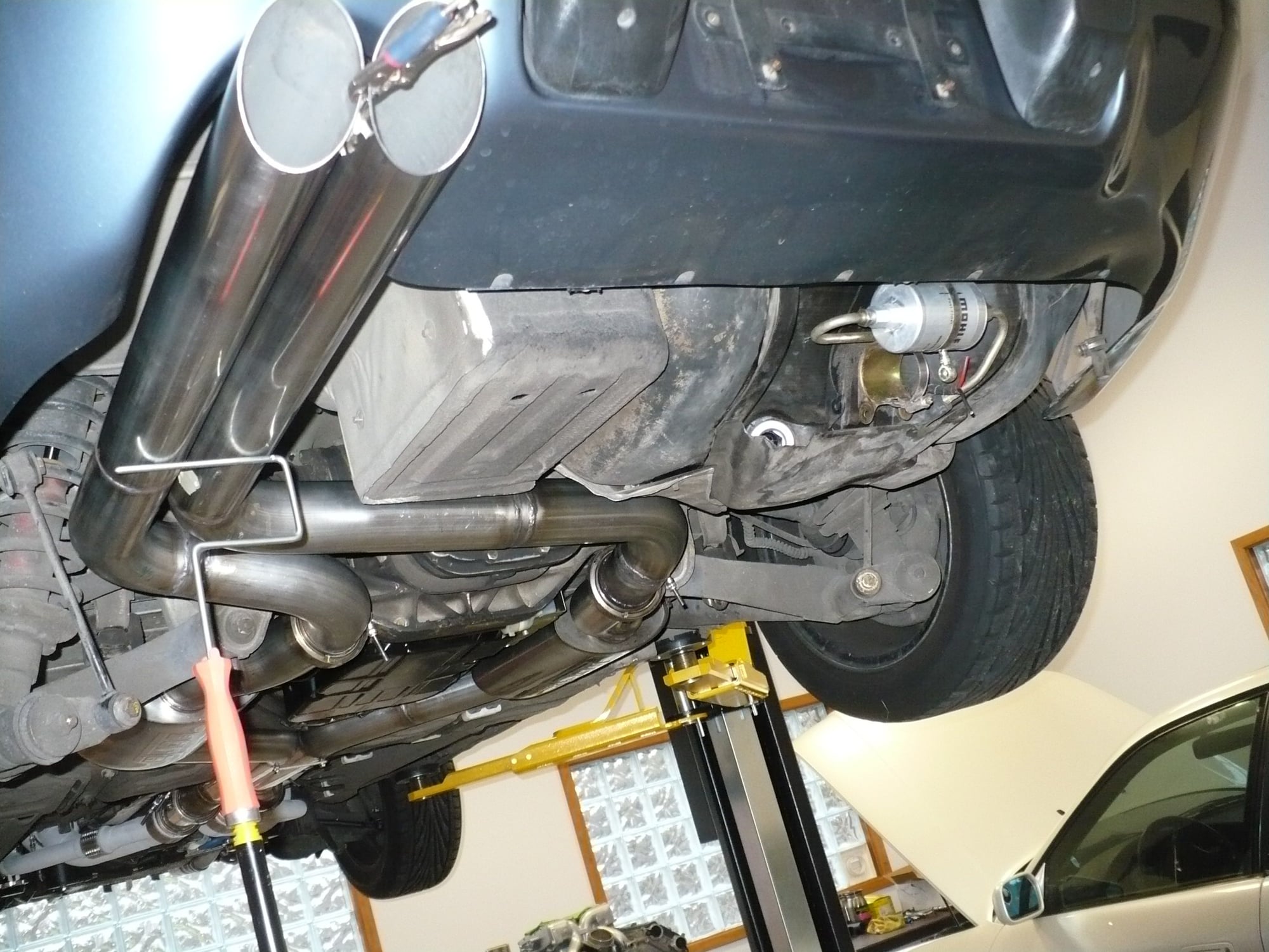
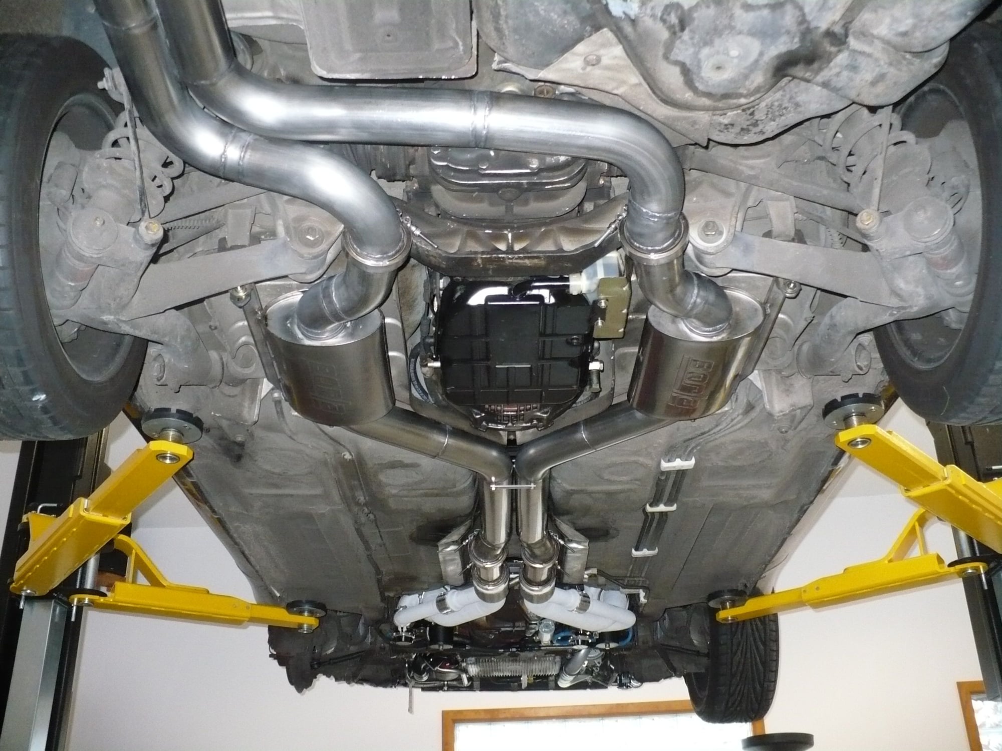
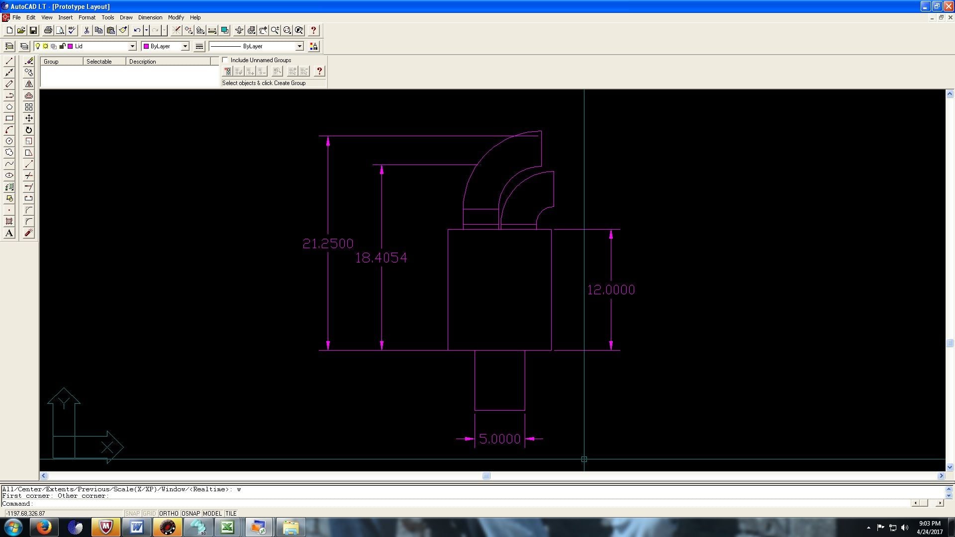
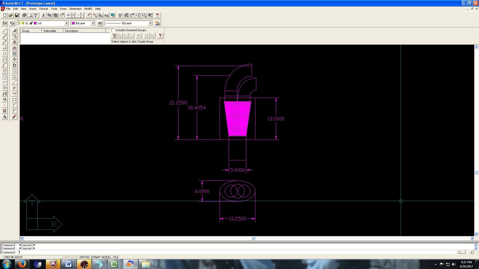
Here are some photos that show the existing exhaust design with 3" inch dual pipes (not my car but the same design) and the beginning of the efforts of designing a bigger exhaust with oval pipe. Right now, it looks like we need everything a little bit bigger starting from the turbine outlet.
The trickiest thing to figure out in the new system is the rear muffler. From sound suppression perspective, I think one needs a rear muffler. The question is what are the requirements for a rear muffler that is fed by two 3.5" pipes.
The sound attenuation is mainly driven by the following formula: h=(m-1/m)^2, where m is the ratio of the pipe area to the muffler cross-sectional area. The frequencies that the muffler mostly impacts is driven by the length of the muffler.
Some observations: When the Borla XR-1 Sportsman muffler can is fed with a single 3.5" pipe, the ratio m is 0.32 and h is 7.85. When the same can is fed with two 3.5" pipes, the ratio is about 0.63 and h is 0.93. It unfortunately doesn't do that much more that a simple pipe merge wouldn't do. Combining pulses however it does do, and it would therefore be better than nothing.
For that tail can muffler to be really effective as a muffler and not just a way to combine pulses, we would need to about double the cross-sectional area for the can compared to the Borla can used as the center muffler per side. We basically need a canister that extends much further down, like a big oval muffler but sideways. Unfortunately, nothing like that is available off the self.
Then, there's the length. The can cancels none of the frequencies that are multiples of 0.5c/l where c is the speed of sound at exhaust temperature (about 500 m/s if the exhaust gas is under 400C by that point) and l is the muffler length (0.3m for that Borla can used at the axle). It cancels the frequencies 0.25c/l + 0.5nc/l the best where n is a positive integer.
If the first muffler has 0.3m length, the second muffler should be either 1.5x the length of the first (0.45m) or 2/3x of the length of the first (0.20m).
The same way, if you have a two-chamber muffler, you probably want to have one chamber be 2/3 the length of the other.
So basically, with all that math, for the requirement you have on backpressure after the turbine, you will have a very loud exhaust.
Just make two paths. One for when you can't be loud, and one nearly open downpipe.
Basically add a cutout,
Originally Posted by ptuomov
Here are some photos that show the existing exhaust design with 3" inch dual pipes (not my car but the same design) and the beginning of the efforts of designing a bigger exhaust with oval pipe. Right now, it looks like we need everything a little bit bigger starting from the turbine outlet.
The trickiest thing to figure out in the new system is the rear muffler. From sound suppression perspective, I think one needs a rear muffler. The question is what are the requirements for a rear muffler that is fed by two 3.5" pipes.
The sound attenuation is mainly driven by the following formula: h=(m-1/m)^2, where m is the ratio of the pipe area to the muffler cross-sectional area. The frequencies that the muffler mostly impacts is driven by the length of the muffler.
Some observations: When the Borla XR-1 Sportsman muffler can is fed with a single 3.5" pipe, the ratio m is 0.32 and h is 7.85. When the same can is fed with two 3.5" pipes, the ratio is about 0.63 and h is 0.93. It unfortunately doesn't do that much more that a simple pipe merge wouldn't do. Combining pulses however it does do, and it would therefore be better than nothing.
For that tail can muffler to be really effective as a muffler and not just a way to combine pulses, we would need to about double the cross-sectional area for the can compared to the Borla can used as the center muffler per side. We basically need a canister that extends much further down, like a big oval muffler but sideways. Unfortunately, nothing like that is available off the self.
Then, there's the length. The can cancels none of the frequencies that are multiples of 0.5c/l where c is the speed of sound at exhaust temperature (about 500 m/s if the exhaust gas is under 400C by that point) and l is the muffler length (0.3m for that Borla can used at the axle). It cancels the frequencies 0.25c/l + 0.5nc/l the best where n is a positive integer.
If the first muffler has 0.3m length, the second muffler should be either 1.5x the length of the first (0.45m) or 2/3x of the length of the first (0.20m).
The same way, if you have a two-chamber muffler, you probably want to have one chamber be 2/3 the length of the other.
So basically, with all that math, for the requirement you have on backpressure after the turbine, you will have a very loud exhaust.
Just make two paths. One for when you can't be loud, and one nearly open downpipe. Basically add a cutout,
This new exhaust is designed to work without valves, but as a contingency plan there's a location at which a cutout valve can be installed if the system isn't quiet enough at low rpms and low loads. Basically, the valve would block half the flow paths and turn the blocked flow path into two quarter wave resonators. The exact location of the valve would determine which frequencies would be cancelled. In addition, the area ratio of the rear muffler would double. Adding moving valves to the exhaust is only a contingency plan at this point, however.
so your car needs the equivalent of a turbofan "hush kit"...
they slow down and diffuse the jet exhaust and wrap it in an envelope of cooler air to knock noise down ~10db.
ford and chevy diesels use a sort of "venturi exhaust tip" to cool off the exhaust gas exiting the pipe during their DPF "regen" periods by letting outside air get pulled in by the rushing exhaust gas.
wonder if something similar could be made to cut down noise.
so your car needs the equivalent of a turbofan "hush kit"... they slow down and diffuse the jet exhaust and wrap it in an envelope of cooler air to knock noise down ~10db. ford and chevy diesels use a sort of "venturi exhaust tip" to cool off the exhaust gas exiting the pipe during their DPF "regen" periods by letting outside air get pulled in by the rushing exhaust gas. wonder if something similar could be made to cut down noise.
This system has very specific requirements. Low noise level at low load and low rpms, low back pressure at high load and high rpm. Can be loud at 6000 rpm and full boost, that's not an issue. Turbomachinery in other settings is often run at high load for long times and muffled for that, and the solutions are different. For example, at low load and low rpms, the velocity in my pipes is not very high and the exhaust isn't very hot and there's really no need to bring in outside air (if I've understood the concern correctly).
The plan is to get the exhaust as quiet as possible at low loads with acceptable (very low) high-load back pressure and to do that using a purely passive system. Once we've taken the passive system as far as we can, then we'll evaluate the need for an active valve. Moving components, such as valves, in car exhaust are always unreliable, especially anything that is made by the "performance" aftermarket industry, so I'd rather not put anything like that in the pipes if it can be avoided. Wastegate is already enough for me.
To get the passive system as quiet as possible, we need to avoid unwanted resonances. The different segment lengths need to be acoustically different length and they can't (or at least shouldn't) have acoustic length that is a low-order integer multiples of each other. Getting to what I call "acoustic length" which may be a total misnormer I need not only the physical length of the segment but also the speed of sound at each segment, which requires a model of exhaust cooling. Here's what I've got so far on that department, after looking at our measurements and reading some papers on the topic. I'm thinking that the below might be ball-park correct for high-load operation:
80 Ambient temperature F
14.7 Ambient pressure psia
459.67 R at zero F
1400 Turbine outlet temperature F
3 Pipe length in m
2 Back pressure psig
0.75 Temperature decay coefficient per m
3.5 Turbine outlet pipe diameter OD inches
0.065 Pipe wall thickness inches
Distance from turbine outlet m, Gas temperature F, Gas pressure psig, Density ratio relative to turbine outlet, Constant velocity flow area sqin, Equiv. single pipe OD inches, Equiv. dual pipe OD, inches Speed of sound m/s, SoS ratio relative to turbine outlet
0.00 1400 2.000 1.000 17.84 4.90 3.50 644 1.00
0.50 1223 1.667 1.083 16.47 4.71 3.37 613 0.95
1.00 1070 1.333 1.167 15.28 4.54 3.25 584 0.91
1.50 937 1.000 1.251 14.26 4.39 3.14 558 0.87
2.00 823 0.667 1.335 13.37 4.26 3.05 535 0.83
2.50 723 0.333 1.415 12.60 4.14 2.96 514 0.80
3.00 637 0.000 1.493 11.95 4.03 2.89 494 0.77
I'm officially getting psyched about this new exhaust.
It'll take some time to build and it'll not be cheap even just from the perspective of materials cost, but we've figured out some things in the process about noise and flow that are very satisfying.
Among othert things, we'll need some custom fabricated oval pipe, three inconel bellows, a bunch of 3.5" bends, a couple of Borla mufflers, and the materials to fabricate a custom rear muffler with modular outlet configuration.
When I had my 944 Turbo the best exhaust was 3" at the downpipe and increased in steps up to 4 inches before the rear muffler.
If the best exhaust is taken to mean the one that makes the most power, approximating a megaphone with gentle cones or small steps like that is probably the ideal thing to do with the turbo-back exhaust.
However, if one wants to get an efficient tradeoff between noise suppression and power for a street car, then I think one should do the opposite. That is, first gently expand the cross-sectional area from the turbine outlet like you'd do with the race car. After that maybe three feet out of the turbine, one should in my opinion start reducing the pipe size and cross-sectional area gently. The reason for that is that the exhaust gas cools and its density increases as it moves thru the pipes. Compared to the turbine outlet, the density may go up 50% over the length of the car, allowing the same velocity (and thus the same back pressure generation) with one 2/3 of the pipe area or 82% of the pipe diameter. That is, if one runs 3" at the turbine outlet, then one can run 2.5" at the tailpipe. Muffling a 2.5" tailpipe pipe with the same muffler case cross-sectional area is a whole lot easier than muffling a 3" tailpipe. This is what all the car factories do, the tail pipe is a lot smaller than the pipe under the car -- of course then they'll tag on massive tips for the visual effect... Get the hormones running for us boy racers walking in to the dealer's showroom with our checkbooks in our hands.
Since my car is somewhere in between these two extremes, what we'll probably do is go up from the dual 3" turbine outlets to dual 3.5" in the downpipe (including the wastegate merge) and then run dual 3.5" all the way to the rear muffler. At the rear muffler, we'll take advantage of the exhaust gas cooling and the reduced pulsation and step it down to single 4.5" for the tail pipe with the perforated Y-pipe inside the muffler. This Y-pipe will have about 16% reduction in flow area. This (we hope) will be a good compromise between minimizing back pressure at high loads and suppressing noise at low loads.
There are a bunch of other tricks planned for noise suppression in this new exhaust, it'll be interesting to see if they work as well in steel as they work on paper...


 04-18-2017, 06:04 PM