When you click on links to various merchants on this site and make a purchase, this can result in this site earning a commission. Affiliate programs and affiliations include, but are not limited to, the eBay Partner Network.
I was expecting the oil stream to be like a high-pressure fire-hose, but it's simply slow 'n steady.
I know that the oil's primary job is to lubricate the engine, and secondarily to cool it, so oil-flow thru the squirters need to be measured/throttled so as to not impede lubrication in any way.
Have you guys run any flow-tests to eyeball the spray pattern and measure volume?
Because of other commercial projects, John Kuhn has a full test rig with correct viscosity test fluid for testing oil system components. Of course he hooked up these squirters to the test rig, how could you resist!?
These are the same squirter components that were used in the early �87 S4. They produce a pencil-like spray pattern that at 928 S4 oil pressures fly much further and flow much more than those about 0.25l/minute MG squirters In the video. I don�t have the exact figures, but it�s a lot more.
Because these squirters came with one model year 928, because they only open at relatively high pressure, and because the 928 S4 oil pump is very oversized at high rpms, I don�t think there is any chance of us running out of the oil pump capacity because of these squirters.
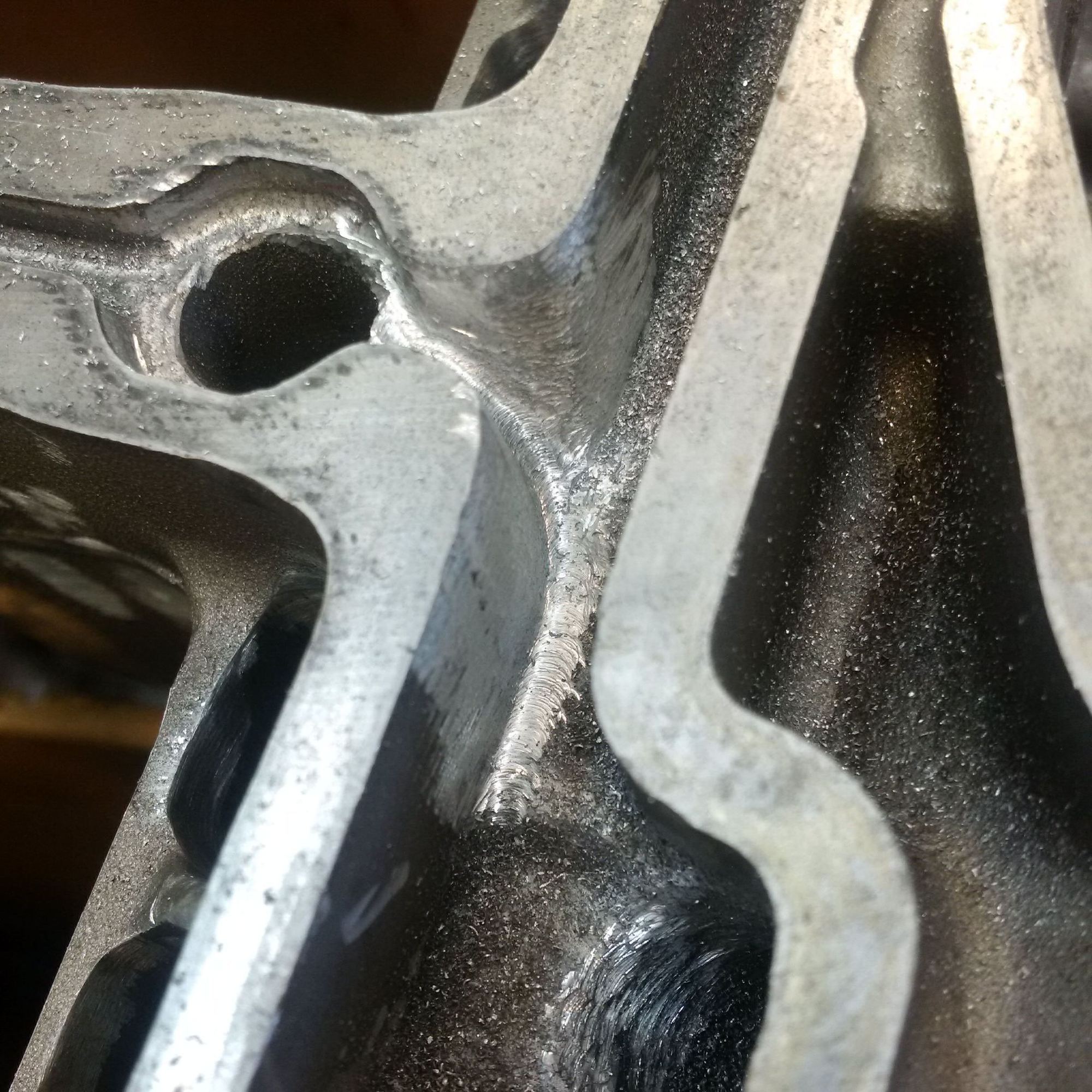
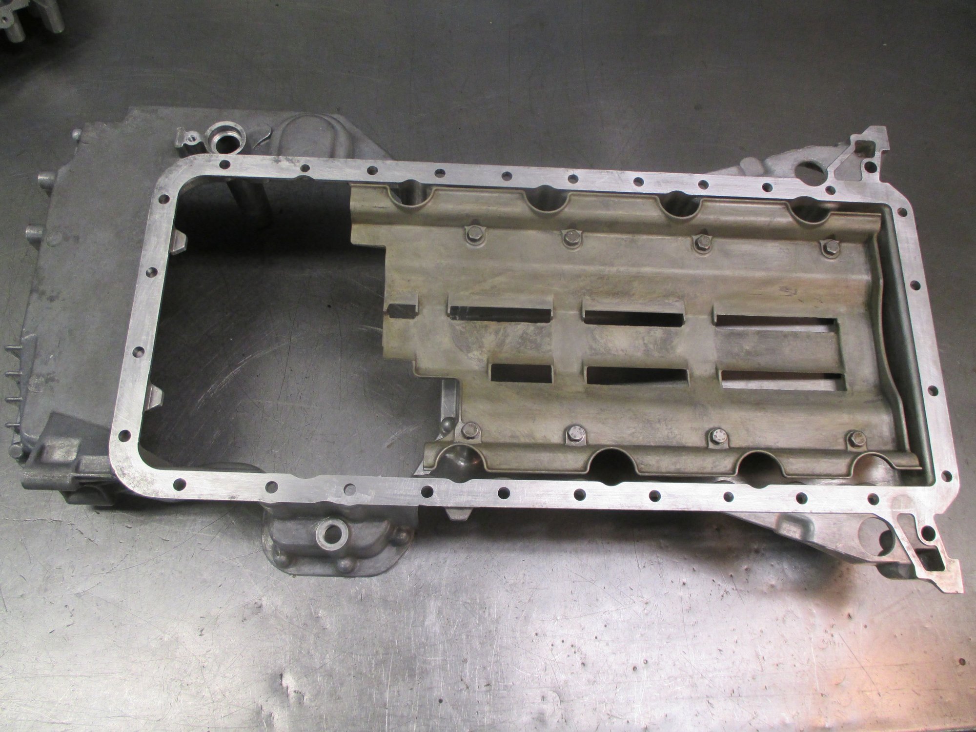
Here�s some work in progress. John Kuhn is hand reshaping the girdle oil passage junction to main #2. The objective is to make it less of an air-oil separator that sends air to #2 and oil further down in the passage. The physics principles are based oil being denser than air, and thus ending up on the bottom and not wanting to turn. Photo:
Here�s some work in progress. John Kuhn is hand reshaping the girdle oil passage junction to main #2. The objective is to make it less of an air-oil separator that sends air to #2 and oil further down in the passage. The physics principles are based oil being denser than air, and thus ending up on the bottom and not wanting to turn. Photo:
Excellent physics implementation to keep the rods and pistons happy
Here�s some work in progress. John Kuhn is hand reshaping the girdle oil passage junction to main #2. The objective is to make it less of an air-oil separator that sends air to #2 and oil further down in the passage. The physics principles are based oil being denser than air, and thus ending up on the bottom and not wanting to turn. Photo:
Should not the far away corner be sharp in order to help the oil to turn?
�ke
Should not the far away corner be sharp in order to help the oil to turn?
�ke
Good question. My layman thinking (not to be confused with a fact) is that you want a relatively sharp edge at the bottom of the channel and a rounded edge at the top, if the air is at the top and the oil is at the bottom. In a sense, the rounded edge at the top gives air another chance to get back to the main channel if the oil from the bottom pushes up. It's all speculation and hypothesizing, and will remain so as I don't think this version will get a plexiglass bolted on it for experiments.
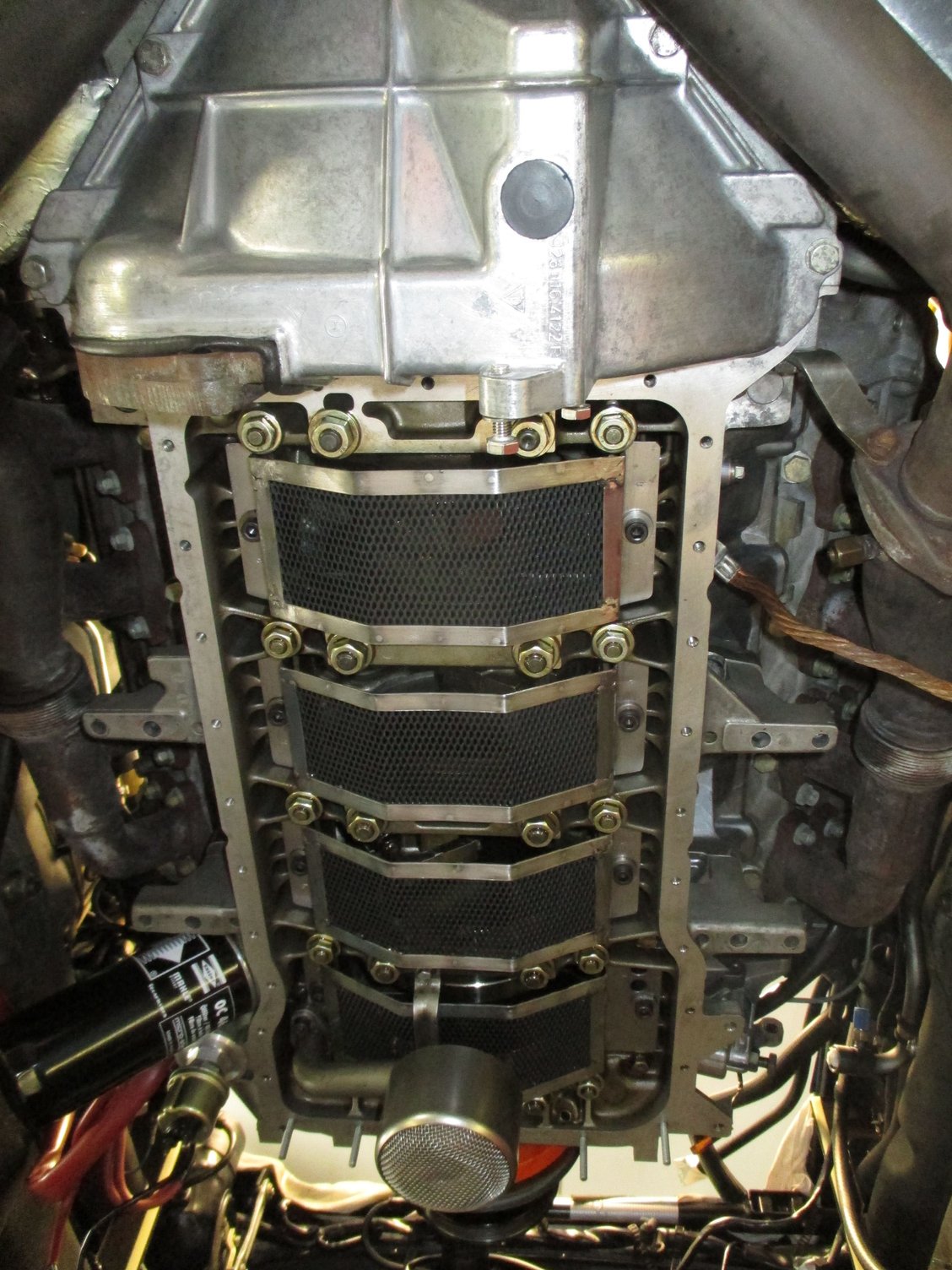
Your oil control system reminds me of Ihihara-Johnson Crank Scraper and Windage Tray but not exactly the same. Is it your own design? You do not show the inside of the oil pan. For the blue car I made my own windage tray (first picture) for testing and it seems to work alright. The second picture show how the oil scraper is designed for the BMW Alpina V8.
�ke
Last edited by Strosek Ultra; 06-14-2020 at 01:11 PM.
That is an Ishihara-Johnson crank scraper - looks exactly like mine.
NLA from Ishihara-Johnson. Suppose that is the system sold by Carl. Pictures from Ishihara-Johnson show a GTS system.
SwayBar how does it work for your engine?
�ke

 05-23-2020, 10:29 AM