
Cruise control and speedometer failure.
 08-03-2008, 12:30 AM
#1
Under the Lift
Lifetime Rennlist
Member
Lifetime Rennlist
Member
Thread Starter
I'm trying to help George Suennen with the failure of his cruise control and speedo in his 90 S4. This is going to be long because I don't know what I am doing.
The failure sequence happened over 10 minutes of normal driving, rare as that is in George's 530+ RWHP car. First, the cruise control started acting up. Then the digital speed readout began to read 20 MPH below analog, then the digital speed readout failed, and finally the analog speedo failed. Curious sequence.
Based on George's description, I thought perhaps the CC brain went kabloey, but from the wiring diagrams, it appears to get the pulse sender signal as an input while the signal goes on unmodified to the instrument panel.
Today we tested the signal at the pulse sender. We spun the rear wheels while checking for an Ohm pulse across the sender wires and picked up nothing. Testing a new sender off the car with a magnet pass, we got a clear on/off signal. So, we installed the new sender, which actually turned out be very easy. Still no speedo. So, we tested the old sender with the magnet, and it responded like the new one.
We went back and spun the wheels and we got a signal, although it was not regular. We got a signal every 1/2 revolution, and 2 signals would be close together, then a space, then another 2. Since the magnet holder is mounted on the differential in line with the ring gear we should get 8 evenly spaced pulses per revolution, but maybe using an Ohm meter just isn't reliable. The sender appears to act like a switch, and we were using continuity testing as an indicator. And since we are getting SOME on/off signals, we expect SOME speedo indication, if erratic. Have the magnets been known to fall out of the carrier plate? This is a PSD, and the magenetic carrier appears to be unlike the earlier versions.
I have reviewed the wring diagrams again and again. You can look at the files I have attached. Added color highlights are not wire-accurate. The two wires from the sender connect to two brown/red wires and go into a harness (WH12) in the automatic cars. Both wires then go to connector T7, which is a 4-pin that is supposed to be located in the spare tire well. George's well is hacked up with a fuel cell, but I checked my car, which is supposed to have the same 4-pin connector, and I cannot find it. The wires from the sender go into a large harness which meanders off towards the front of the car. After passing through the missing T7, the 2 red/brown wires are supposed to pass through a 26-pin connector T19 "near the CE panel". You'd think a 26-pin connector would be easy to spot, but we cannot find T19. From T19 one wire goes to ground. We confirmed that the ground path is intact back at the the sender plug. The other red/brown wire goes from T19 to pin 11 on the cruise control before going on to the instrument cluster plug 4.
It still puzzles me that the CC acted up for 10 minutes before the analog speedo failed. So, you can understand why I thought the brain was suspect, and maybe it should be. But that is a black box to me. They are known to fail, but I don't know if George's failure mode could happen from CC brain failure.
HELP!
Can CC brain falure account for this?
Where exactly is connector T7?
Where exactly is connector T19?
What do you think of the irregular pulse based on ON/OFF continuity testing result across the pulse sender wires?
The failure sequence happened over 10 minutes of normal driving, rare as that is in George's 530+ RWHP car. First, the cruise control started acting up. Then the digital speed readout began to read 20 MPH below analog, then the digital speed readout failed, and finally the analog speedo failed. Curious sequence.
Based on George's description, I thought perhaps the CC brain went kabloey, but from the wiring diagrams, it appears to get the pulse sender signal as an input while the signal goes on unmodified to the instrument panel.
Today we tested the signal at the pulse sender. We spun the rear wheels while checking for an Ohm pulse across the sender wires and picked up nothing. Testing a new sender off the car with a magnet pass, we got a clear on/off signal. So, we installed the new sender, which actually turned out be very easy. Still no speedo.
So, we tested the old sender with the magnet, and it responded like the new one.We went back and spun the wheels and we got a signal, although it was not regular. We got a signal every 1/2 revolution, and 2 signals would be close together, then a space, then another 2. Since the magnet holder is mounted on the differential in line with the ring gear we should get 8 evenly spaced pulses per revolution, but maybe using an Ohm meter just isn't reliable. The sender appears to act like a switch, and we were using continuity testing as an indicator. And since we are getting SOME on/off signals, we expect SOME speedo indication, if erratic. Have the magnets been known to fall out of the carrier plate? This is a PSD, and the magenetic carrier appears to be unlike the earlier versions.
I have reviewed the wring diagrams again and again. You can look at the files I have attached. Added color highlights are not wire-accurate. The two wires from the sender connect to two brown/red wires and go into a harness (WH12) in the automatic cars. Both wires then go to connector T7, which is a 4-pin that is supposed to be located in the spare tire well. George's well is hacked up with a fuel cell, but I checked my car, which is supposed to have the same 4-pin connector, and I cannot find it. The wires from the sender go into a large harness which meanders off towards the front of the car. After passing through the missing T7, the 2 red/brown wires are supposed to pass through a 26-pin connector T19 "near the CE panel". You'd think a 26-pin connector would be easy to spot, but we cannot find T19. From T19 one wire goes to ground. We confirmed that the ground path is intact back at the the sender plug. The other red/brown wire goes from T19 to pin 11 on the cruise control before going on to the instrument cluster plug 4.
It still puzzles me that the CC acted up for 10 minutes before the analog speedo failed. So, you can understand why I thought the brain was suspect, and maybe it should be. But that is a black box to me. They are known to fail, but I don't know if George's failure mode could happen from CC brain failure.
HELP!
Can CC brain falure account for this?
Where exactly is connector T7?
Where exactly is connector T19?
What do you think of the irregular pulse based on ON/OFF continuity testing result across the pulse sender wires?
Last edited by Bill Ball; 08-03-2008 at 01:04 AM.
 08-03-2008, 05:15 PM
#2
Racer
Join Date: Aug 2008
Location: ft lauderdale
Posts: 427
Likes: 0
Received 0 Likes
on
0 Posts
I have a 89s4, The CC never worked, and it's a common failure in these cars ( I owned a 82, and it didn't work in that one either), The Speedo and digital dash conked out on me also. I went thru every fuse in the panel, found one blown, replaced it...and guess what? Everything lit back up like a Christmas tree.
08-03-2008, 05:33 PM
#3
Under the Lift
Lifetime Rennlist
Member
Lifetime Rennlist
Member
Thread Starter
It is true that a blown interior light fuse will take out the gauges, but it affects more than the speedo.
Still reviewing more of the wiring diagrams and finding the CC brain connects up with a gaggle of other devices including the bulb control unit. WTF for? Maybe to get the brake (light) signal for cutting the CC. That doesn't sound like the right way to do it, though.
Found a digital speedometer "A" output from the instrument panel that connects to the kickdown relay too. I'm getting more confused.
Since the CC failed before anything else, I should probably start there, although I don't get how it affects the speedo. In most cars when the CC brain fails, the speedo keeps working and it looks like it should here as well.
Last edited by Bill Ball; 08-04-2008 at 04:44 PM.
08-03-2008, 06:38 PM
#4
Addict
Lifetime Rennlist
Member
Lifetime Rennlist
Member
Bill,
T7 is a two wire connector only on automatics. It is screwed to the body near the spare tire. If you replaced the sender you must have opened the connector up to replace the pins. If the car is a 5-speed it should be a 4 wire connector.
T7 is a two wire connector only on automatics. It is screwed to the body near the spare tire. If you replaced the sender you must have opened the connector up to replace the pins. If the car is a 5-speed it should be a 4 wire connector.
08-03-2008, 06:46 PM
#5
Three Wheelin'
Join Date: Sep 2007
Location: Ridgecrest, California
Posts: 1,363
Likes: 0
Received 147 Likes
on
31 Posts
Hello Bill,
Sorry to hear about your '90 S4 Cruise/Speedo problem. I've worked quite a bit on the '84 CC and speedo but the 90 is different. I can say that on the '84, I've tested many CC amps (brains) - about 20 - some would not work at all, some worked rather unpredictably, and some worked correctly. But none of them affected the speedometer. On the '84, the CC uses a branch signal off the pulse sensor while the other branch goes to the instrument cluster (speedo) - sounds like the same set up as the 90. Also, I have not tried to test the speedo pulse sensor using an Ohm meter. I used an analog mulit-meter set for 12V DC so I could watch the pulses as the wheels turned. This seemed to be a very reliable method of testing the pulse sensor but it requires power (ignition key in "on/run") or the engine running. Sorry I don't have better info to help....good luck.
Sorry to hear about your '90 S4 Cruise/Speedo problem. I've worked quite a bit on the '84 CC and speedo but the 90 is different. I can say that on the '84, I've tested many CC amps (brains) - about 20 - some would not work at all, some worked rather unpredictably, and some worked correctly. But none of them affected the speedometer. On the '84, the CC uses a branch signal off the pulse sensor while the other branch goes to the instrument cluster (speedo) - sounds like the same set up as the 90. Also, I have not tried to test the speedo pulse sensor using an Ohm meter. I used an analog mulit-meter set for 12V DC so I could watch the pulses as the wheels turned. This seemed to be a very reliable method of testing the pulse sensor but it requires power (ignition key in "on/run") or the engine running. Sorry I don't have better info to help....good luck.
08-03-2008, 07:00 PM
#6
Addict
Lifetime Rennlist
Member
Lifetime Rennlist
Member
The first to check is what the CC and speedo have in common. From the wiring diagram it looks like pin nr. 11 on the CC plug.
08-03-2008, 07:08 PM
#7
Under the Lift
Lifetime Rennlist
Member
Lifetime Rennlist
Member
Thread Starter
George's is an automatic. Yes, we found the two-wire connector, which is the harness plug for pulse sensor. The wiring diagram seems to show a separate 4-pin T7...and according to the connector key chart, it includes the backup light for automatics (Field coordinate P5). We can see another 3 pin connector and a couple of 6 pins (that have only 5 wires).
Trending Topics
08-03-2008, 07:35 PM
#8
Addict
Lifetime Rennlist
Member
Lifetime Rennlist
Member
Bill, the wiring diagram is somewhat screwy here. P5 shows the back up switch for a 5-speed (M481). It should say T28 instead of T7. It also says WH 16.
08-03-2008, 08:08 PM
#9
Three Wheelin'
Bill,
You should see stable 8 pulses per axle rev at the sender using an ohm meter, or voltmeter, or O'scope. Missing pulses could cause some weird sort of error. The sender has to be seated tight in the differential cover as it appears Porsche didn't squander money to put strong magnets inside. Any space at the sender will cause trouble.
When I first got my '90GT running again, I had a very strange problem where the speedometer would work until I put on the brakes, then it quit until I restarted the car. I went all through the speedo sensor wiring, the cruise control circuitry too since the brake light switch connects to the CC module. I finally realized that either one or both brake lights weren't working whenever the speedometer quit. I fixed that and all was good again in the world of speedometer and cruise control. I do wish I could remember what the problem was exactly that fixed it. I believe it was a fuse, but not one you'd normally associate with the speedometer.
08-03-2008, 10:28 PM
#11
Addict
Rennlist Member
Rennlist Member
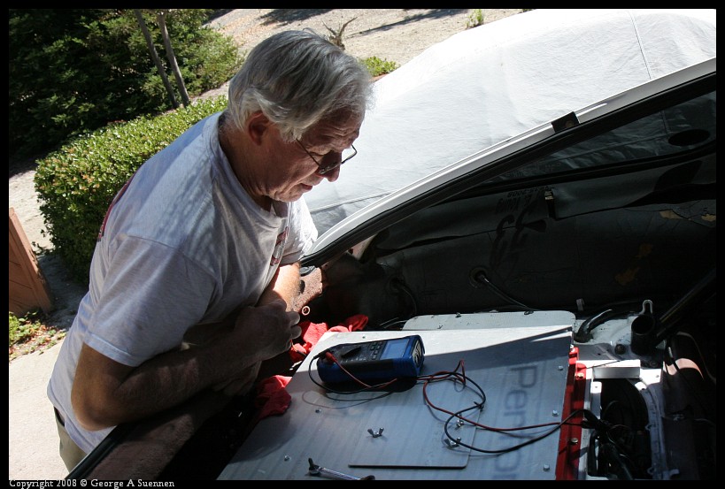
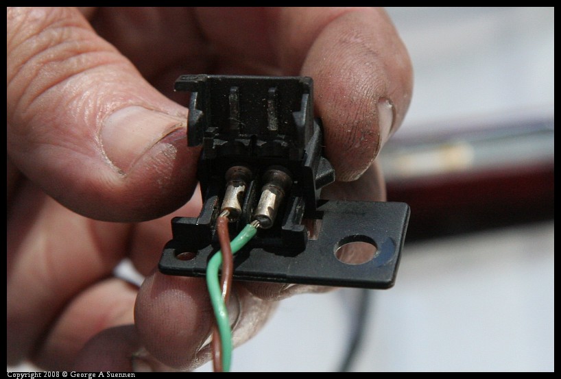
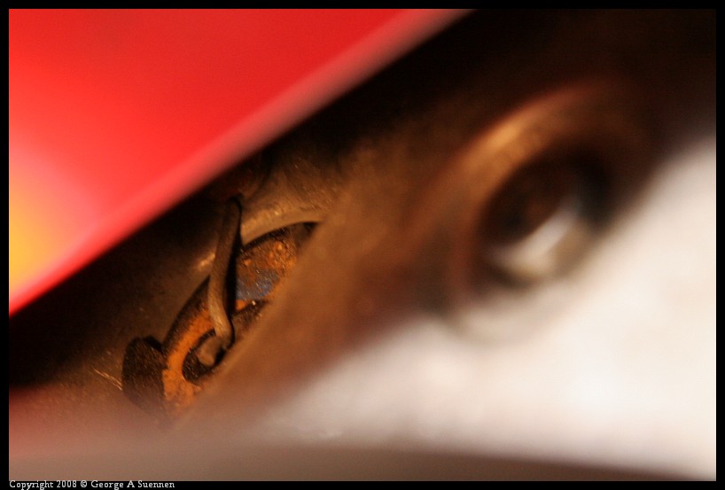
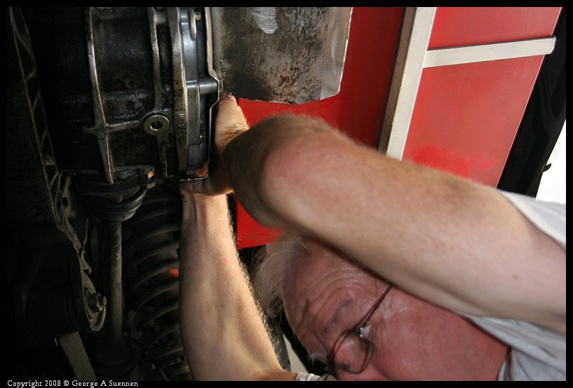
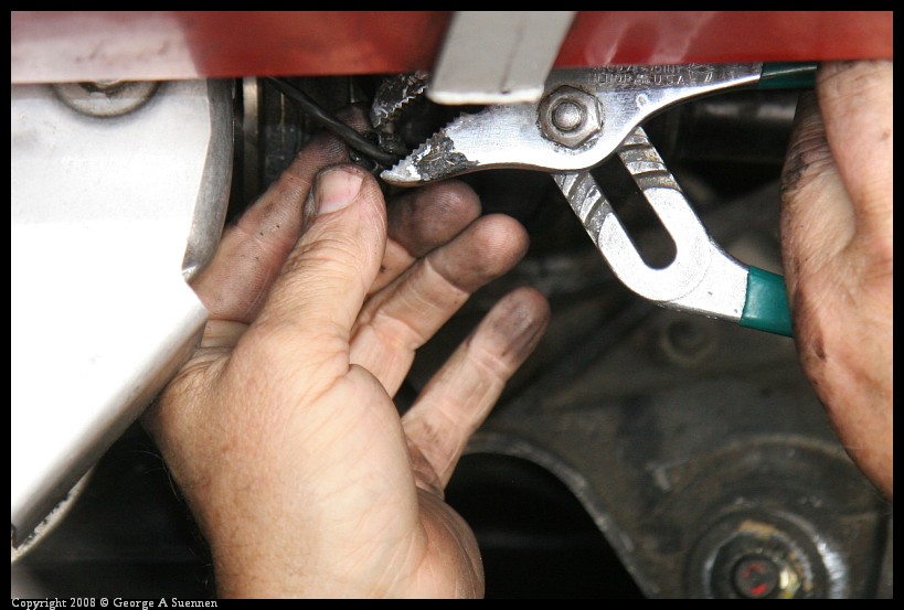
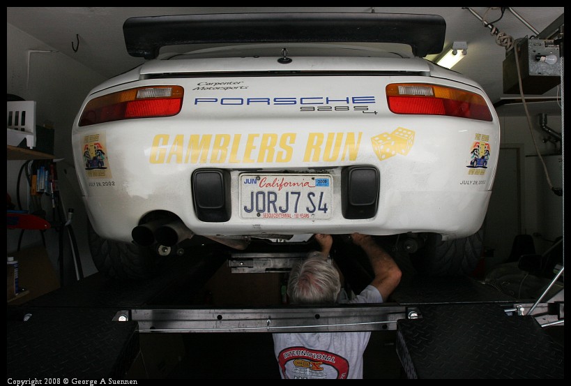
Here are a few photos to add a few details to Bill's description of replacing the speedometer sensor.
1 The sensor plug after it's detacted and unplugged.
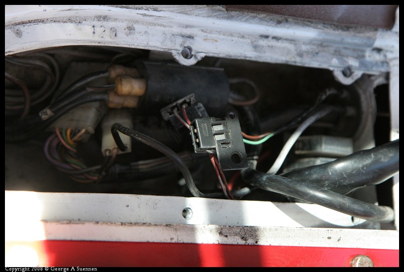
2 Connecting the ohm meter to the plug
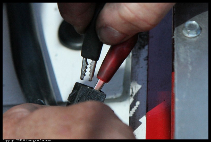
3 Bill checking for continuity while I turn the rear wheel.
4 Inside of the sensor plug. We had to disassemble the plug to get it through the wheel well wall.
5 The speedo sensor mounted at the back of the diff.
6 Tight squeeze getting the nut back on the wire that holds the sensor in place.
7 Put the clip on the wire clip to hold it in place.
8 It's nice to have a lift to do this job Thanks Bill.
1 The sensor plug after it's detacted and unplugged.
2 Connecting the ohm meter to the plug
3 Bill checking for continuity while I turn the rear wheel.
4 Inside of the sensor plug. We had to disassemble the plug to get it through the wheel well wall.
5 The speedo sensor mounted at the back of the diff.
6 Tight squeeze getting the nut back on the wire that holds the sensor in place.
7 Put the clip on the wire clip to hold it in place.
8 It's nice to have a lift to do this job
Thanks Bill.
08-03-2008, 11:14 PM
#12
Three Wheelin'
Here are a few photos to add a few details to Bill's description of replacing the speedometer sensor.
1 The sensor plug after it's detacted and unplugged.
2 Connecting the ohm meter to the plug
3 Bill checking for continuity while I turn the rear wheel.
4 Inside of the sensor plug. We had to disassemble the plug to get it through the wheel well wall.
5 The speedo sensor mounted at the back of the diff.
6 Tight squeeze getting the nut back on the wire that holds the sensor in place.
7 Put the clip on the wire clip to hold it in place.
8 It's nice to have a lift to do this job Thanks Bill.
1 The sensor plug after it's detacted and unplugged.
2 Connecting the ohm meter to the plug
3 Bill checking for continuity while I turn the rear wheel.
4 Inside of the sensor plug. We had to disassemble the plug to get it through the wheel well wall.
5 The speedo sensor mounted at the back of the diff.
6 Tight squeeze getting the nut back on the wire that holds the sensor in place.
7 Put the clip on the wire clip to hold it in place.
8 It's nice to have a lift to do this job
Thanks Bill.
08-04-2008, 12:07 AM
#13
Drifting

T19 connector on my 90' S4..... photo in this thread...
https://rennlist.com/forums/showthre...&highlight=t19
https://rennlist.com/forums/showthre...&highlight=t19
08-04-2008, 01:21 AM
#14
Under the Lift
Lifetime Rennlist
Member
Lifetime Rennlist
Member
Thread Starter
When you are turning the wheel to check the sensor output, what's happening with the other wheel? You have to have the diff ring gear turning to get the sensor to react.
08-04-2008, 01:23 AM
#15
Under the Lift
Lifetime Rennlist
Member
Lifetime Rennlist
Member
Thread Starter
T19 connector on my 90' S4..... photo in this thread...
https://rennlist.com/forums/showthre...&highlight=t19
https://rennlist.com/forums/showthre...&highlight=t19