When you click on links to various merchants on this site and make a purchase, this can result in this site earning a commission. Affiliate programs and affiliations include, but are not limited to, the eBay Partner Network.
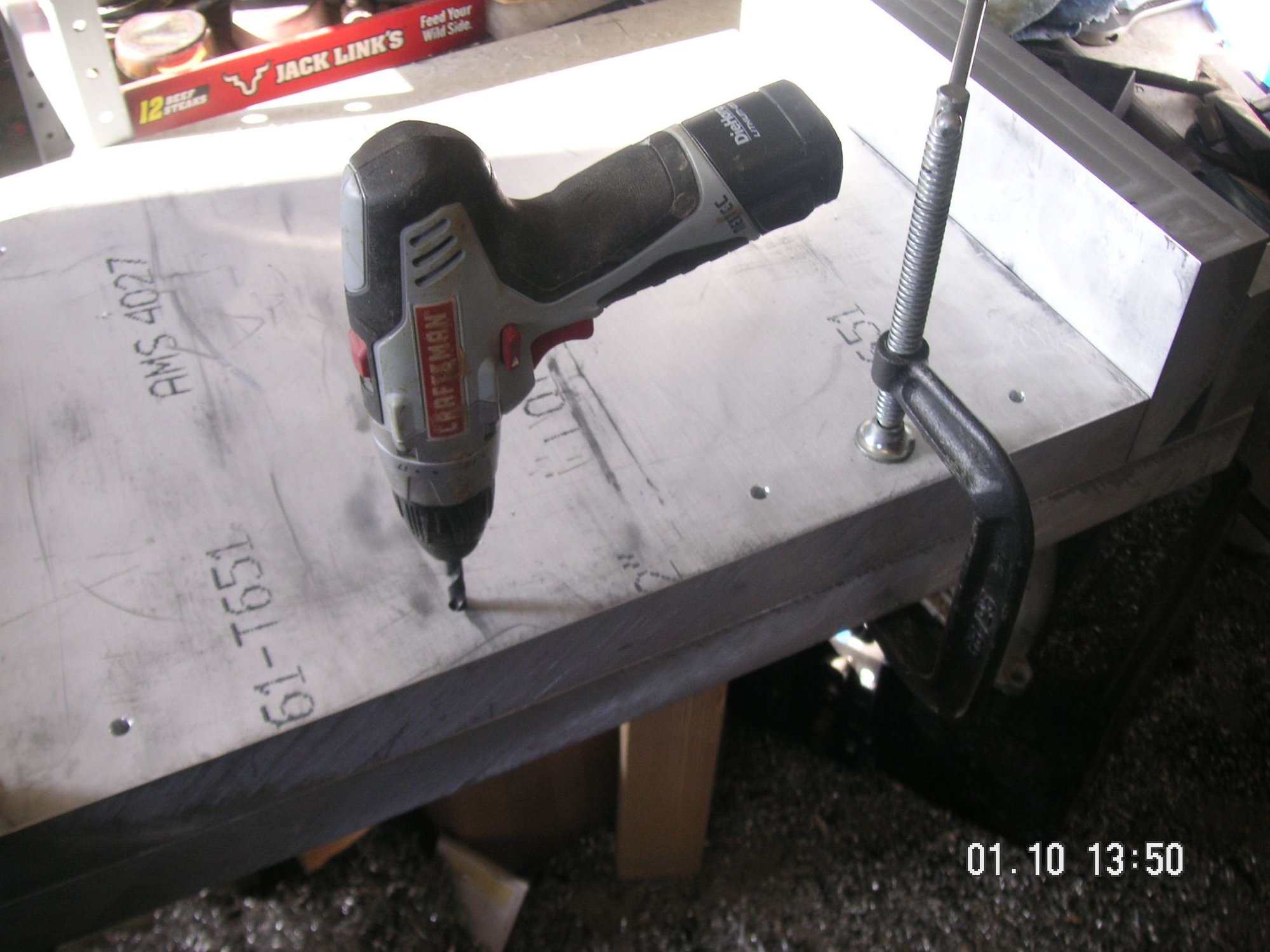
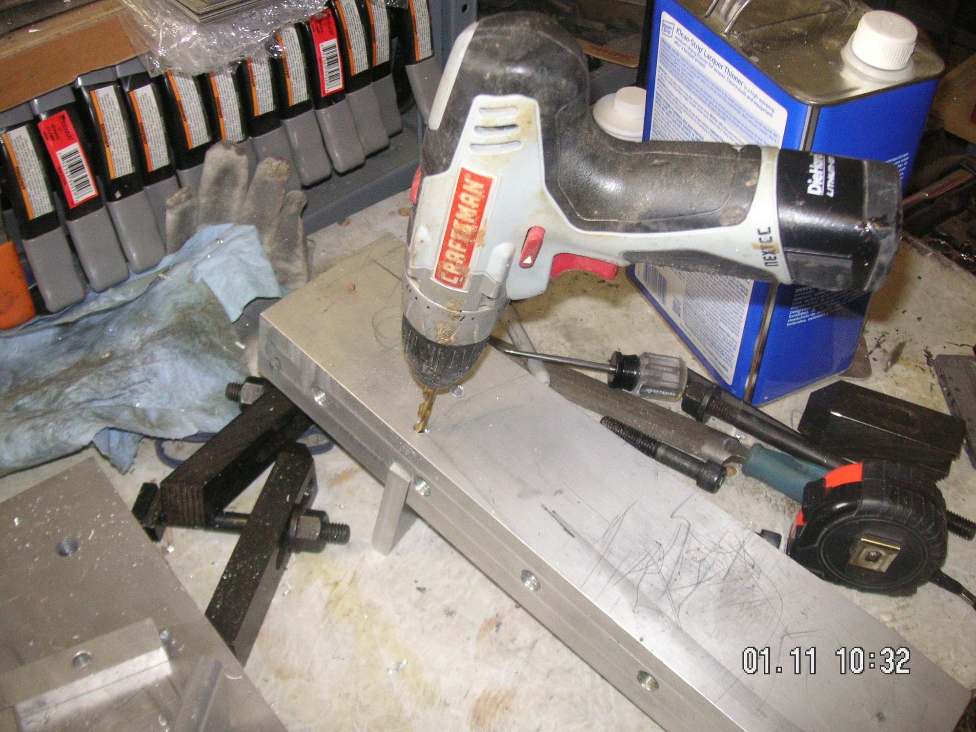
I took the center form plate out of the mill and then drilled the pilot or location holes a little bit into the big base plate. I also discovered that I need to shave a bit off of one end of the center plate. I'll do that the next time I have it in the mill.
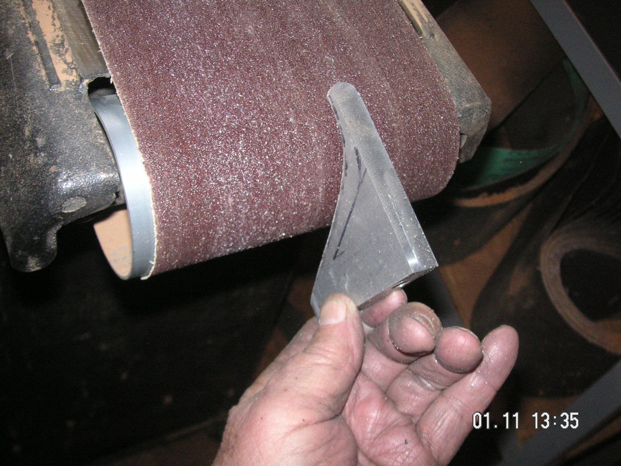
Then maybe I am getting ahead of myself, but I cannot resist trying to start with what I call the details. I put one of the end pieces in the mill and lined it up to cut slots for what wil be bolted in the form to form the two corner stiffeners on the passenger end. Tomorrow I'm going to try to work up those to some extent, at least all but cutting their inner radii. That will entail holes and threads to bolt them in and then milling off the bottoms flat the the base plate. When all three of them are done I'll probably, with my band saw, cut the radii and then finish them by hand with the rounded end of my belt sander.
Last edited by Jerry Feather; 01-11-2020 at 10:15 AM.
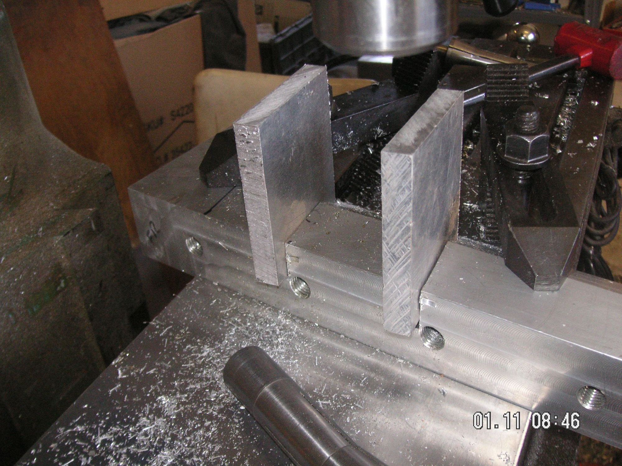
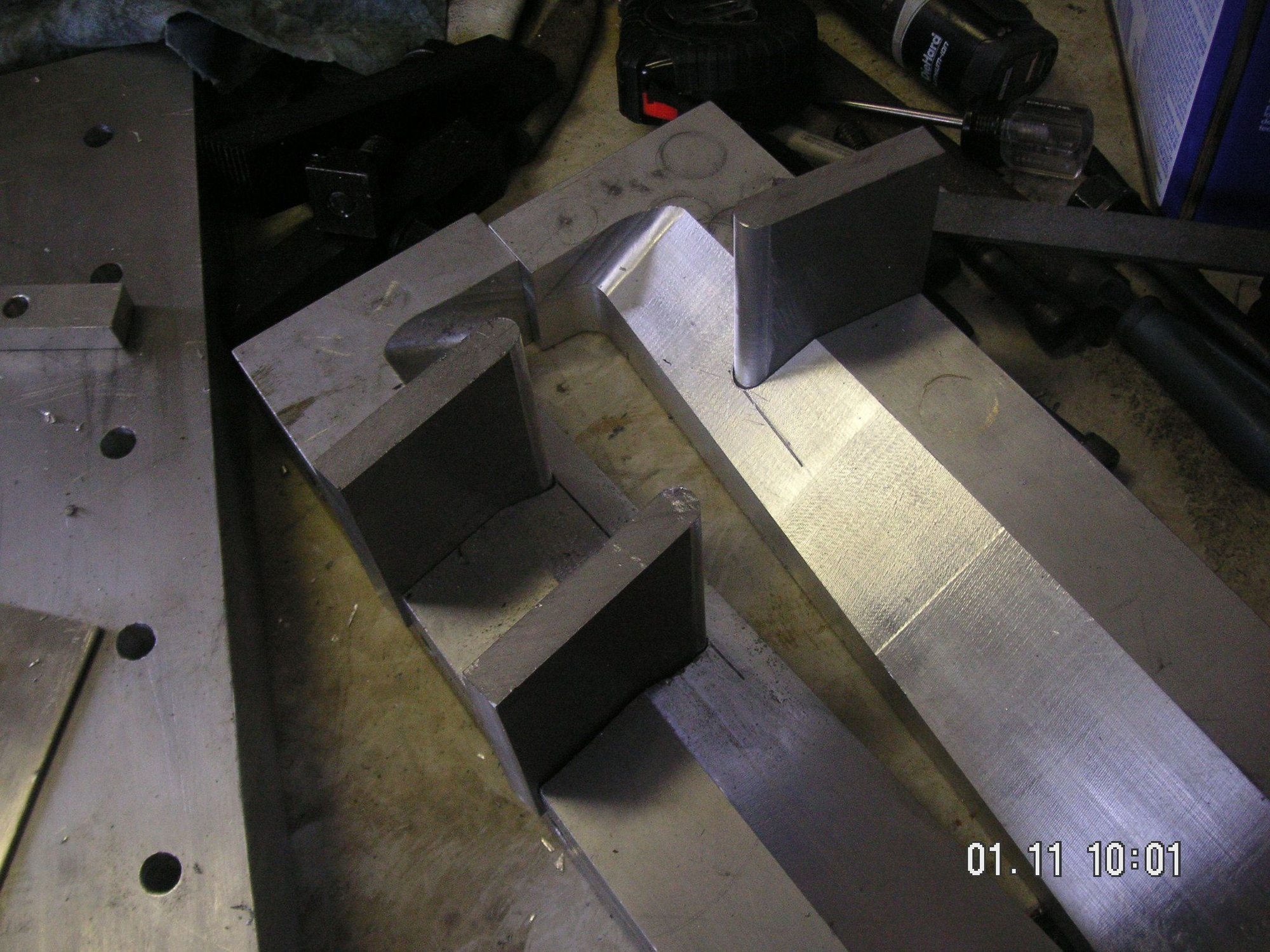
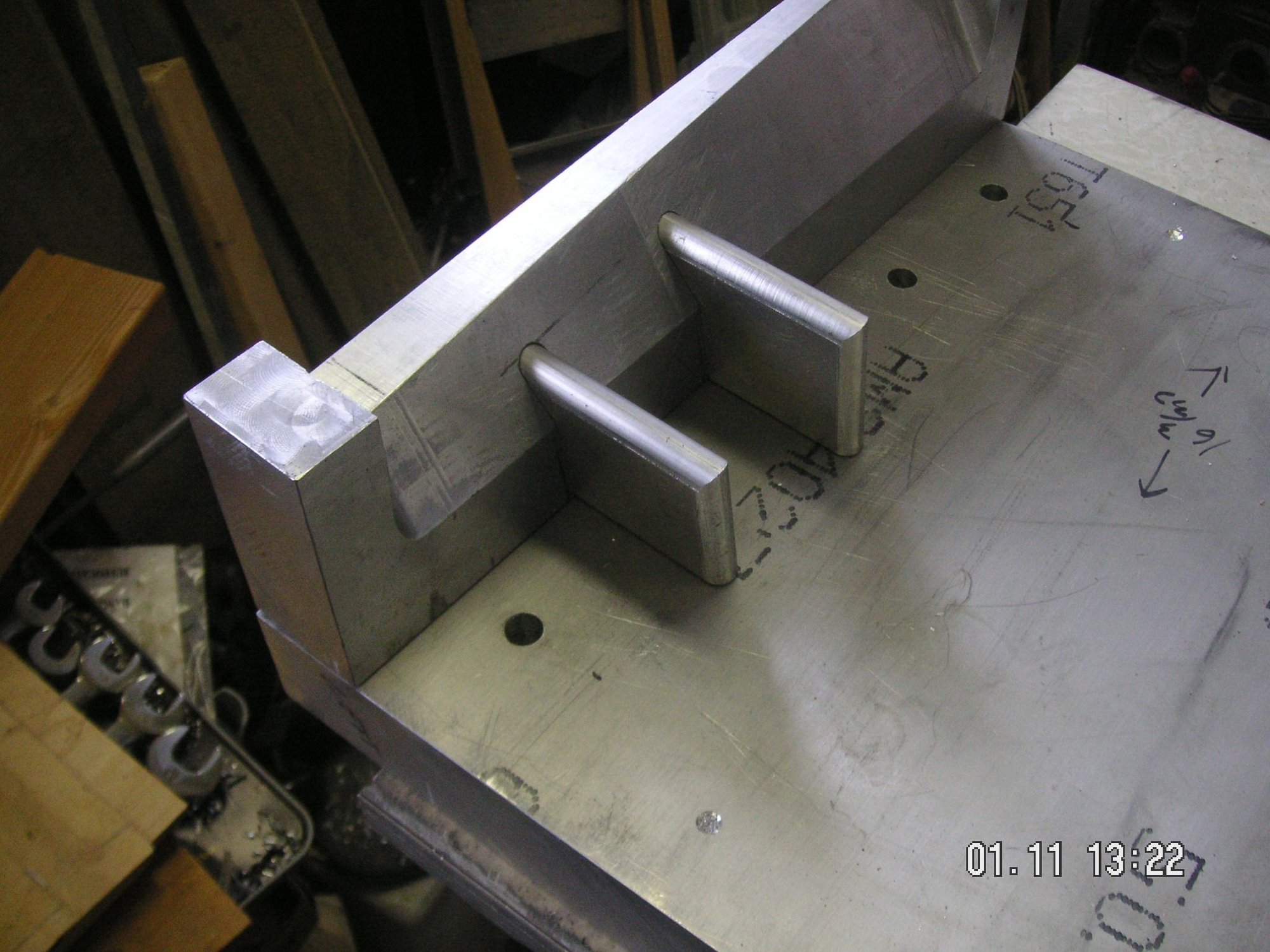
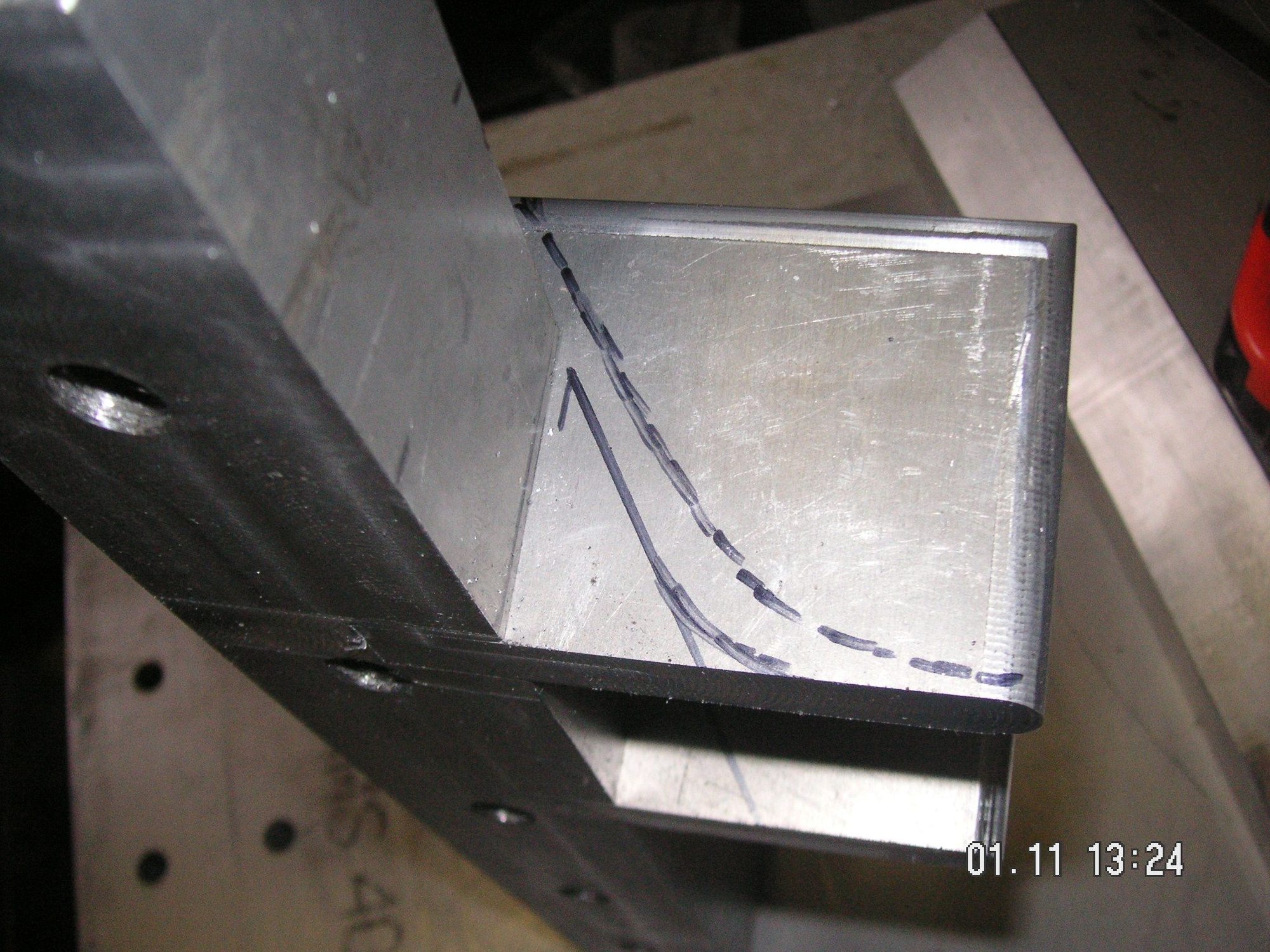
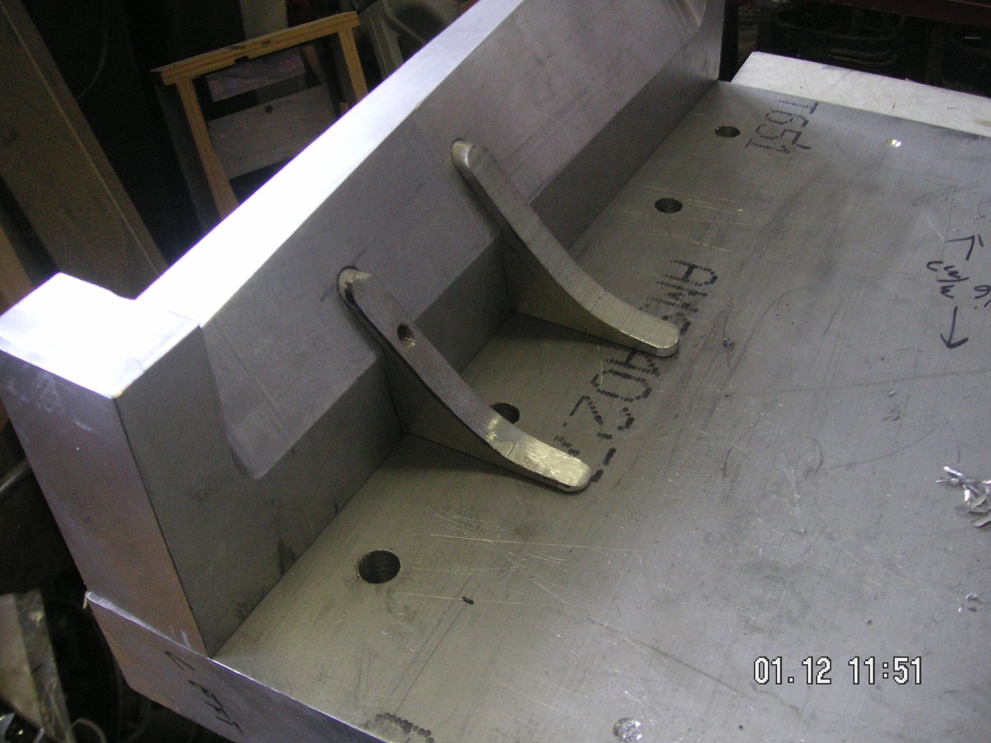
I knew the details were going to take a lot of time and I have spent about 3 hours in the shop this morning woeking on these three corner stiffener form pieces. I am about half way done with them, but thought I would take a break and post a few pictures of where I am so far. I have the two edges of each piece corner rounded and I have all the holes drilled and taed in the pieces. Right now i am opening up the pilot holes in the end pieces and counter boring them for the bolt heads. When I get the rest of those done I'll be able to start with the final shape of the edge of the pieces that will actually be doing the forming.
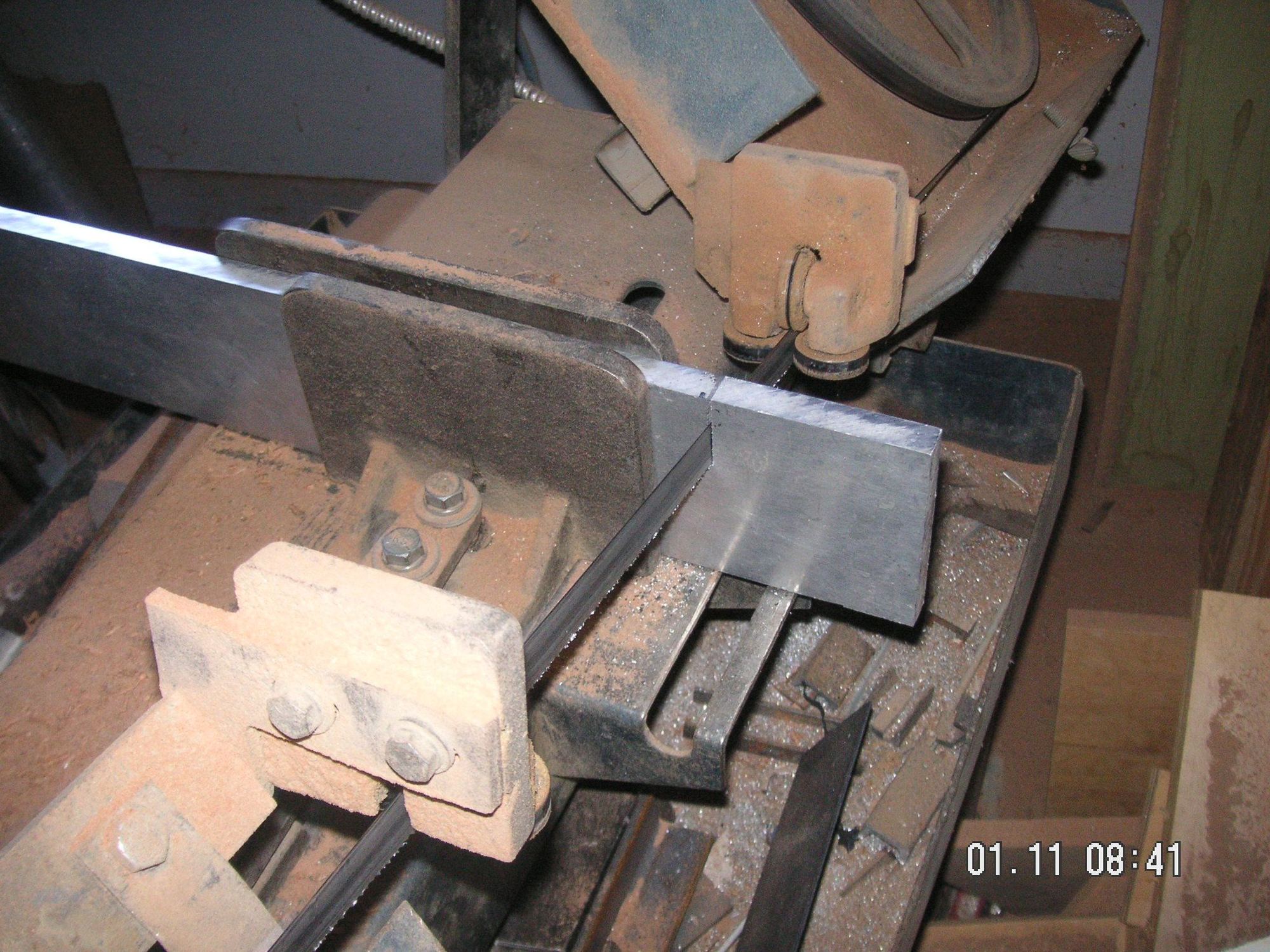
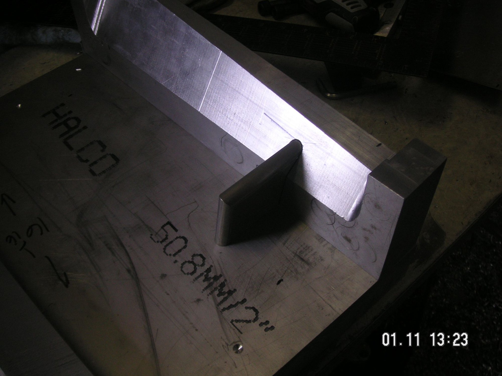
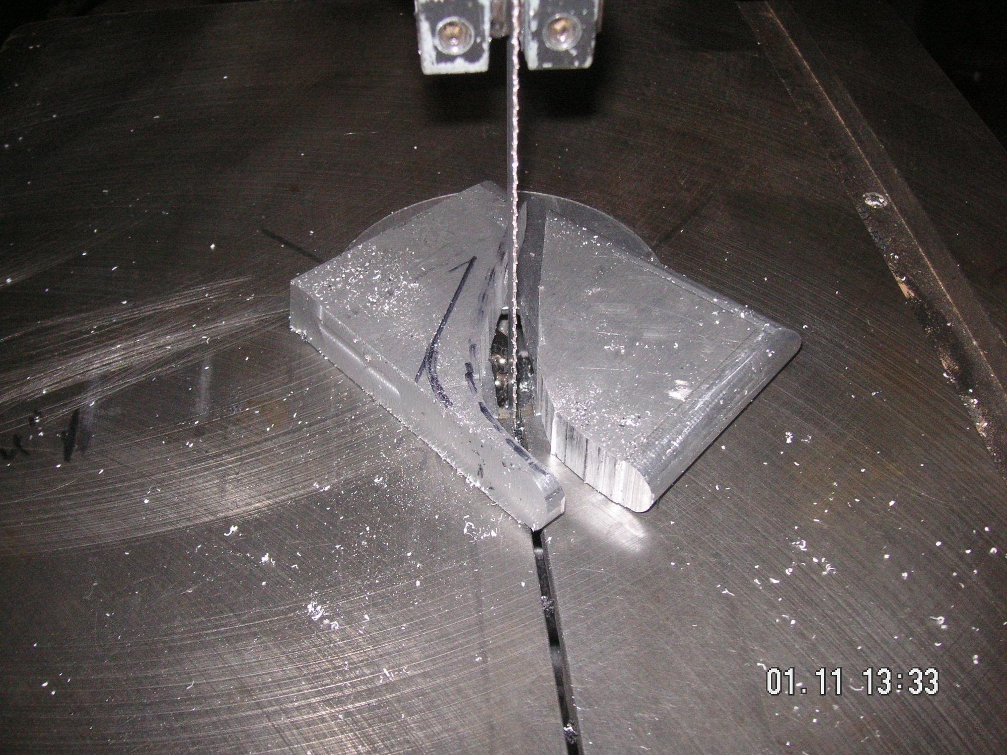
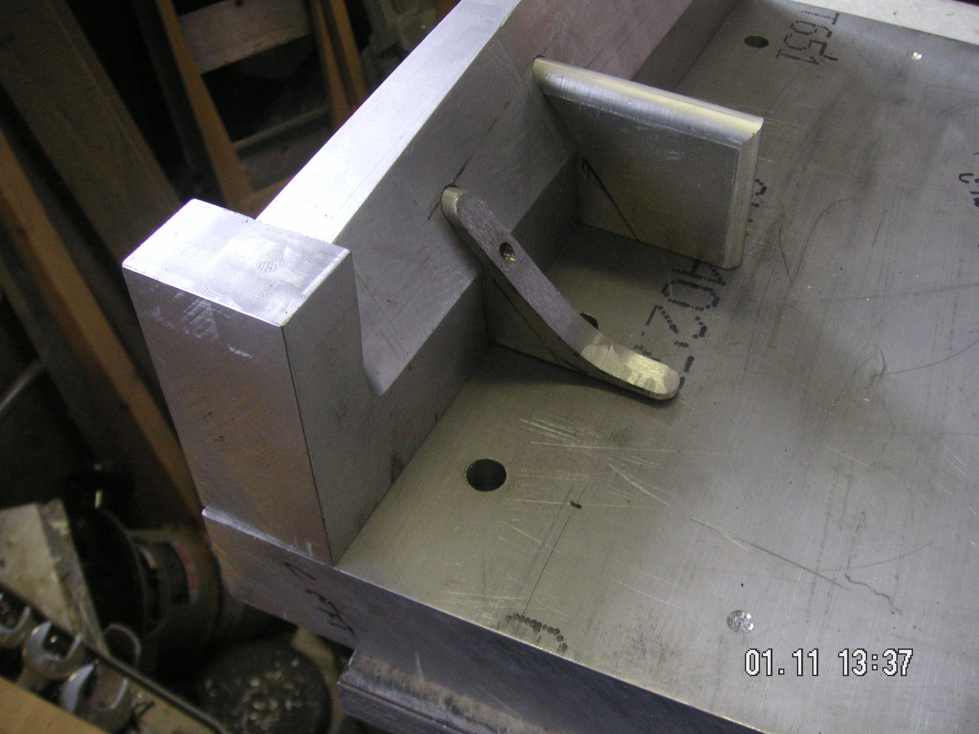
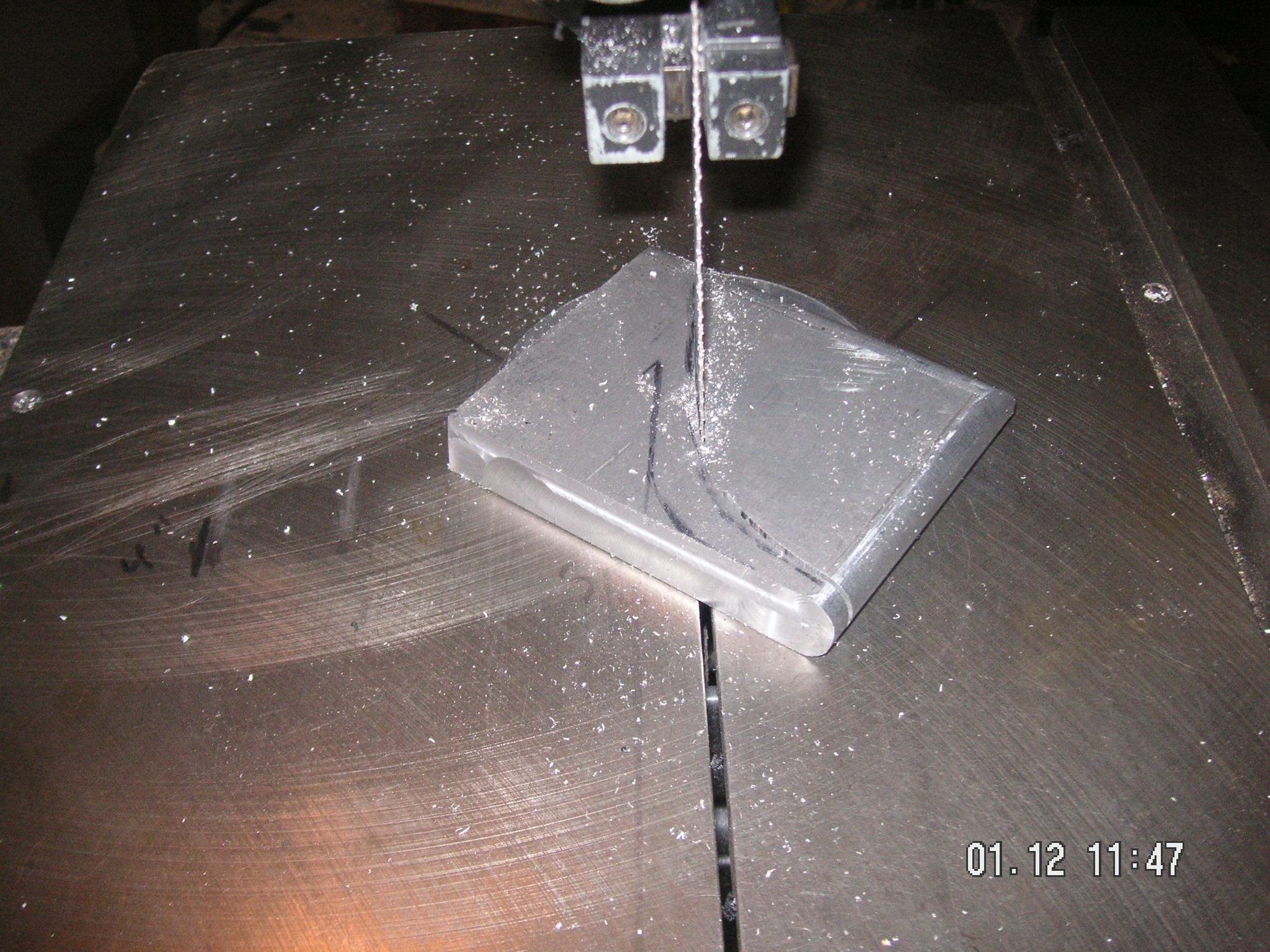
It took a little extra effort to get the bolts to align and screw in, but I got these three detail pieces firmly mounted into the end pieces. Then I milled the bottoms off flat and even with the end piece. Then I finally got to mark them and then cut one of them in the bandsaw to near its final shape. I sanded it a little further, but I'll leave it where it is now before I try for the final shape. That's probably enough for today since my son and his family are coming over shortly to watch football and then I'll cook some steaks for supper. I think I need to go to the store for some rolls, so I guess I am done for today.
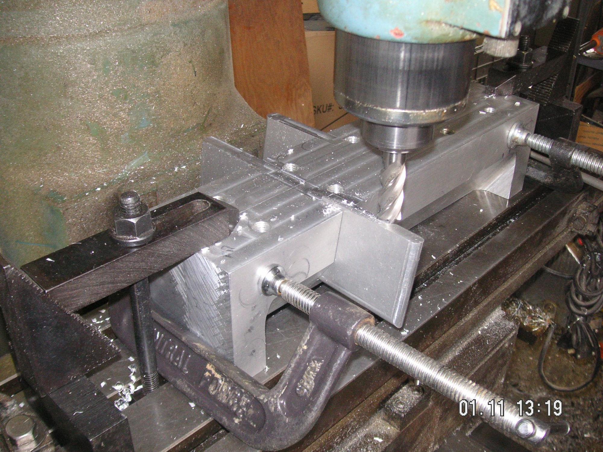
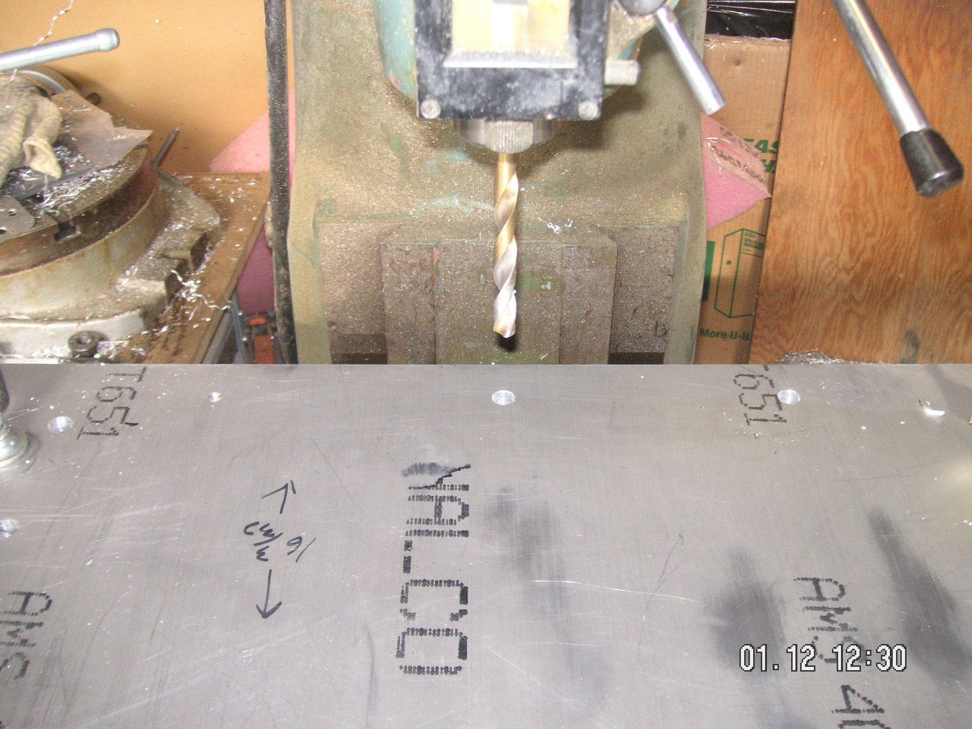
Well, back to the basics, although I did work the threads over for the corner brace forms and cut another one of them to its rough shape. For the basics I put the large base form plate into the mill and drilled the 10 holes to be tapped for the guide and hold down bolts. That might seem like a simple step but it takes a lot of repositioning of the plate in the mill since it is so large and my mill is kind of small. Each hole must be drilled twice, first to the 5/16 inch pilot hole then to the minor size for the half inch threads. Oh, I also cut a couple of bevels that I think I will need to fill in a couple of places between the end pieces where some backup of the metal being formed in needed.
Last edited by Jerry Feather; 04-28-2020 at 01:52 PM.
In the finished plate/pan there is a kind of reverse channel along the front of it. I have that pretty well designed; so while I have the base piece in the mill I'm going to mill the slot for the pieces that will be put in it to form the channel. In the meantime I have been struggling with the size, shape, and design of the two major downward dents or bulges. If the weather stays nice again today I'll try to get under the 85 and do some close measurments to help me with the final design. If I can get those figured out I'll also put their outline shape and depth into the base form while it is still in the mill. It is a real bitch to move in and out of the mill since it is so heavy.
I'm also going to put the outline of the front-to-back kind of ribs into the base while it is in the mill; and although there are three in the original pans I am going to put five in my design. Then too I guess I can also mill a channel for the rear crossways stiffening channel into the base; and maybe even fashion and locate the piece that will fit along the rear of the pan to shape the rear edge. I guess that depends on whether I am going to finish the rear edge up or down. I haven't quite decided yet. Right now my front edge finishes down and forward, and I am thinking that the rear edge ought to finish up and to the rear, but I'm not sure.
Last edited by Jerry Feather; 01-18-2020 at 11:53 PM.
Jerry,
Maybe the trailing edge could have 2 or 3 tabs that could fit into the crossmember or steering rack cover.
That suggestion certainly has merit, John, mainly because as designed the original protection plates are mounted only along the front, and even with 5 points along the front edge, if it wasn't for the two upper mounting points providing some geometry the plate would be simply flapping in the slip stream. As it is all the mounting points being in the front still leaves the plate with essentially no support in the rear. In fact the only support in the rear from anything heavy enough to be protected from is from the items being protected, such as the AC compressor and the alternator.
Nevertheless, I think your suggestion would lead to a whole different kind of protection plate, something akin to the S4 and later plate designed by the factory, since the mounting points you suggest are about a half engine away from the trailing edge of the early pan I am working on. I guess I am not into the design and engineering that your sugggestions will require; and, except for something that can be bolted onto what I come up with, a much larger pan is simply too big for me to consider given my size and weight constraints. Maybe you have some sketchs of what you have in mind that might make it more realistic.
Thanks for your input.
Last edited by Jerry Feather; 04-28-2020 at 01:54 PM.
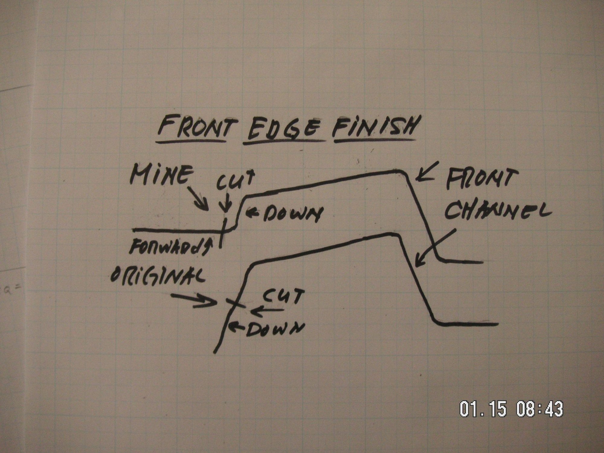
For anyone who might have been puzzled by my description of how I intend to finish the front and rear edges of my plate, down and forward in the front, in particular, here is a sketch of what I mean. As to the rear, I think it will be similar, but up and then to the rear.
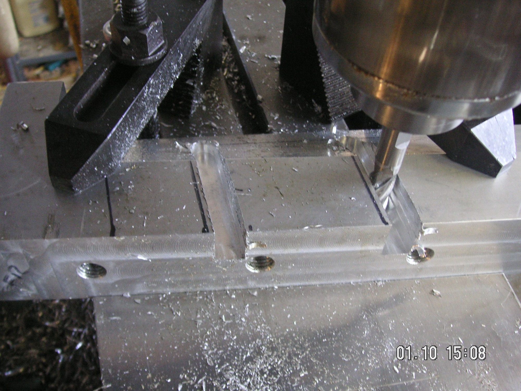
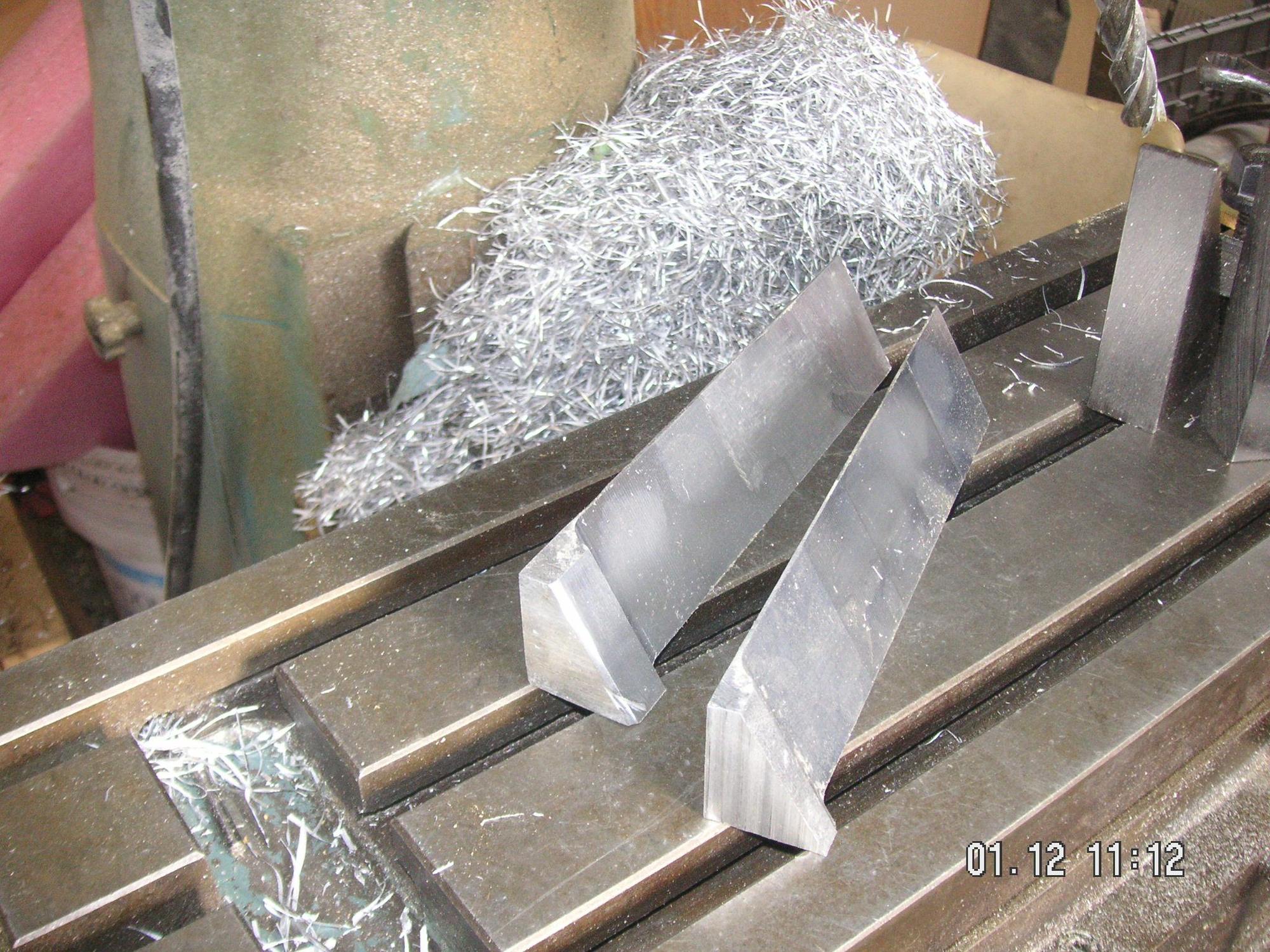
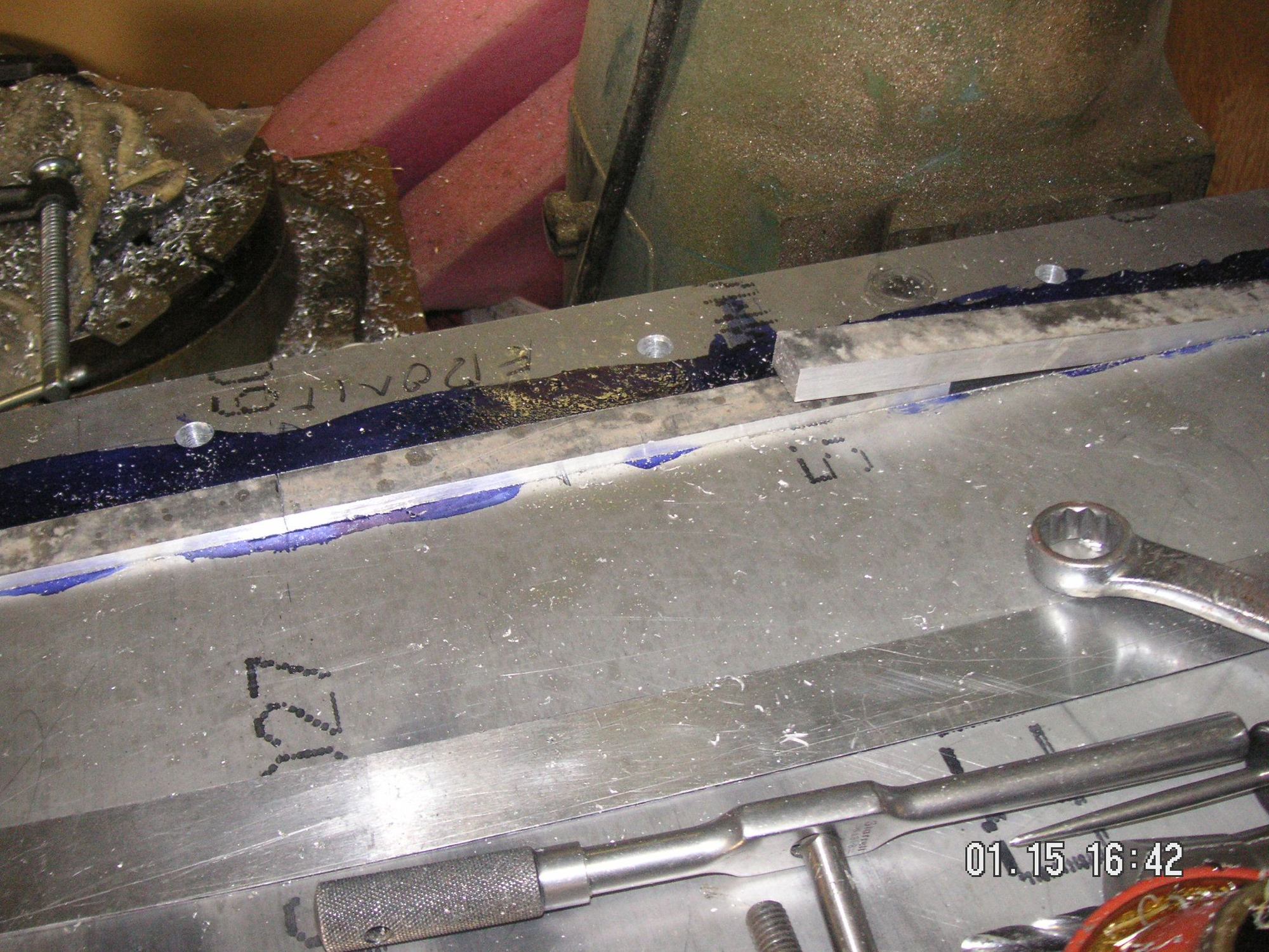
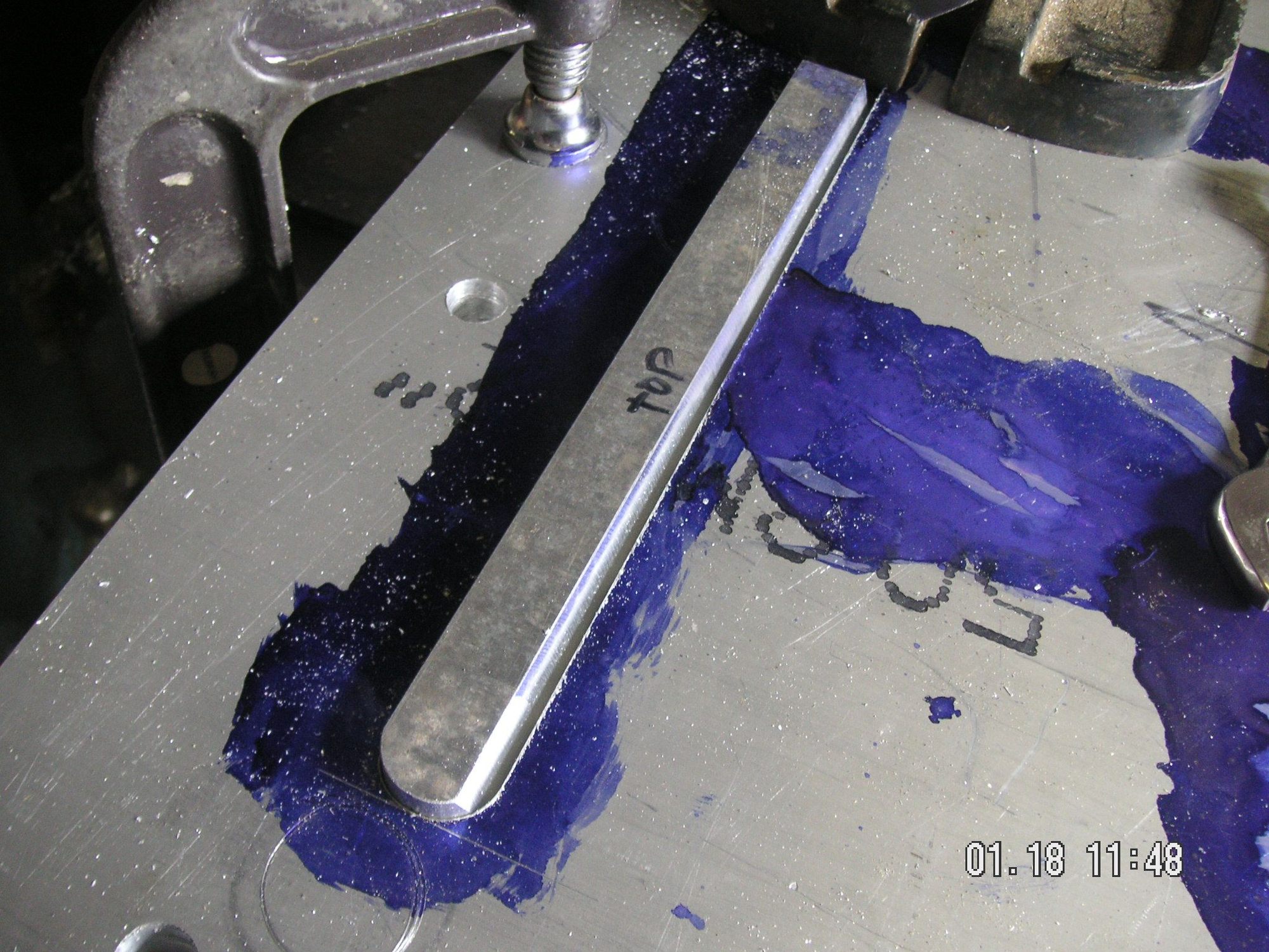
Another detail started. I cut the channel along the front of the base form for the bar stock that will be trimmed to fit the inside of the channel to be formed along the front of the pan. The inside of the channel in the finished piece will be about 5/8 inch wide and will have a slope to it from front to up a little in the back. Theoretically the top flat of it will be about level and the bases of it will kind of slope downward to match the slope or fit of the pan. My sketch above is actually nearly scale to the cross section of the finished pan, but at the point of the front end of the ribs at the 5 mounting points. I was goin to also mill the rib channels, but I couldn't remember the measurements, and besides I had a aluminum chip in the corner of my eye that was bugging me, so I came in for th evening.
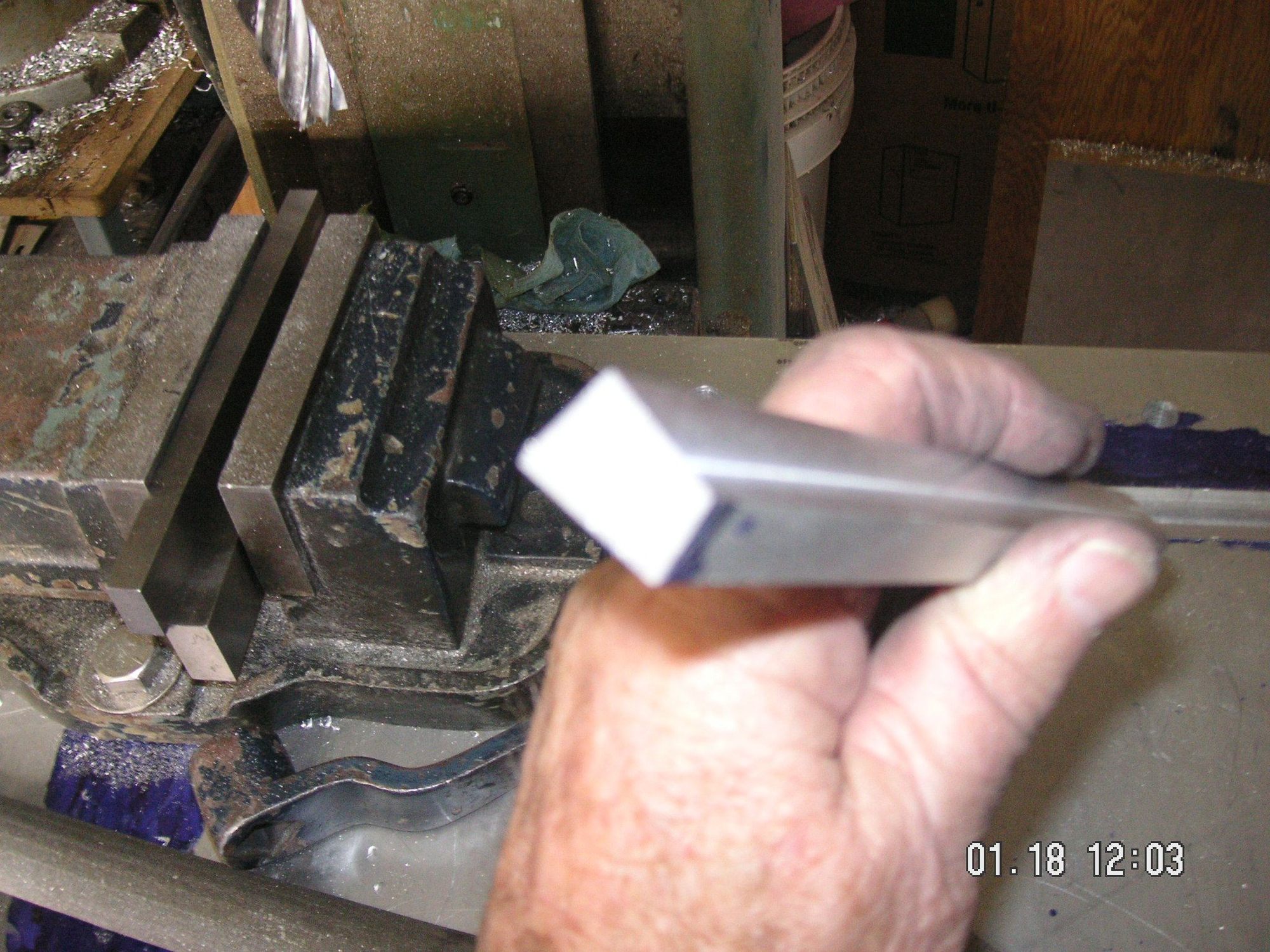
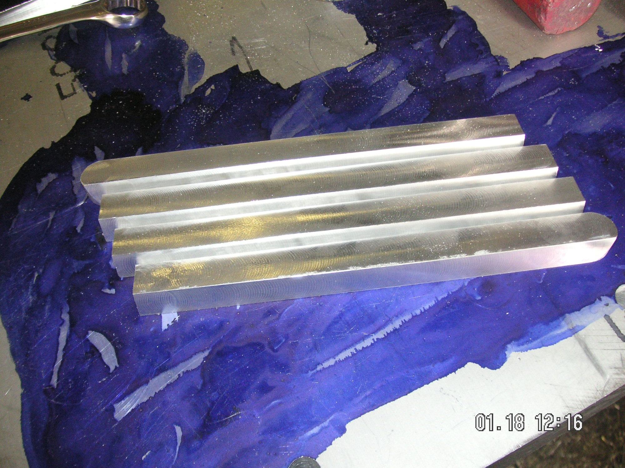
The pieces of half inch by 3/4 inch bar stock, cut to about 8 inches each, are the ones that will actually fit into the channel in the form and will become the form for the channel in the pan. I cut them off of some stock and will have to wait until I get this big piece of aluinum out of the mill so I can put my mill vise back on the table and mill the surfaces of these pieces to their finished shape. I have to use 8 inch pieces rather than one continuous piece since my mill head only articulates in one plane and my mill table moves in the Y direction only about 9 inches. That is where I have to cut the angled surfaces.
Last edited by Jerry Feather; 01-16-2020 at 10:50 AM.
What I cut in the base pieces yesterday I suppose I should be calling a "slot" rather than the channel since it may be confusing about also being there to help form the channel in the finished piece.
I really was hoping to be able to mill the 4 channel form pieces to fit into the slot and then common drill them to fit the slot while the base piece is in the mill. Then, last night it occurred to me that maybe all I need to do is bolt my mill vise to the base piece in the mill and use that to finish and drill the 4 form pieces, then I can common drill them to the base piece. I might even be able to use two of the holes I have already drilled in the base, but I'll have to drill and tap another offset 90 degrees to the row in the base since I'll have to have my vise cross ways to the table for these 4 pieces.
I probably wont get to this out in the shop this afternoon or evening since I have court all afternoon, and this evening I will be picking up the trailer I'm going to use to go to SLC to pick up the 50 ton press I am buying.
Last edited by Jerry Feather; 04-28-2020 at 01:57 PM.
That didn't work out too well. I left here pulling the trailer before 6 yesterday morning and didn't quite make it to the state line before my truck failed. I was able to turn around at an interstate crossover at or near the line and get about 5 or 6 miles back toward home, still about 25 miles away, before the engine quit totally. I sat there in the cold for about 3 hours waiting for my buddy with the tow truck; and now I have a big expense to get the truck fixed. I'm not sure yet what effect that is going to have on my purchase of the press.
I did get to do some more measurements under the 85, so I am getting closer to the final design of the pan layout. I'll be working on some of that out in the shop as soon as I finish my coffee this morning.
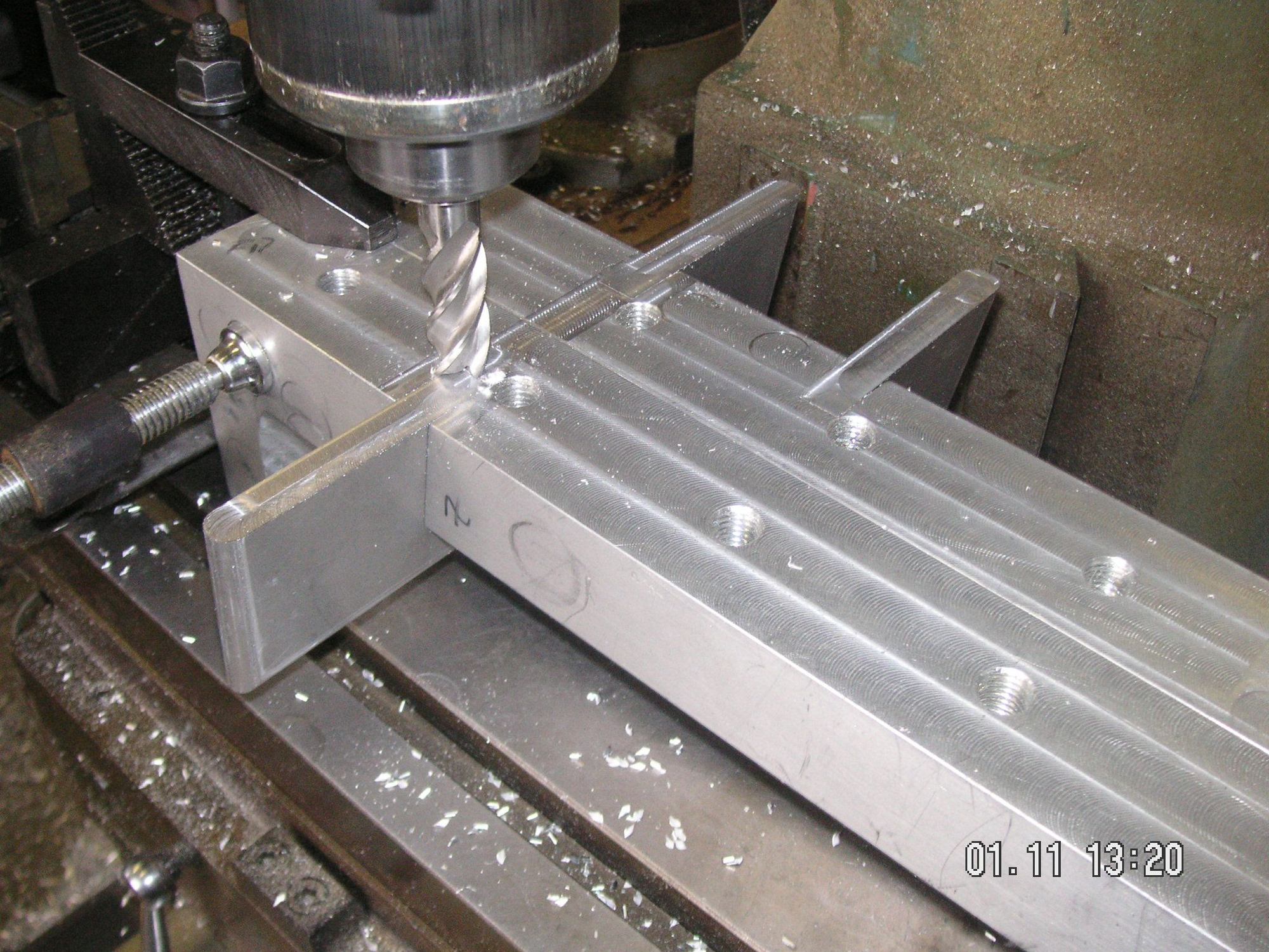
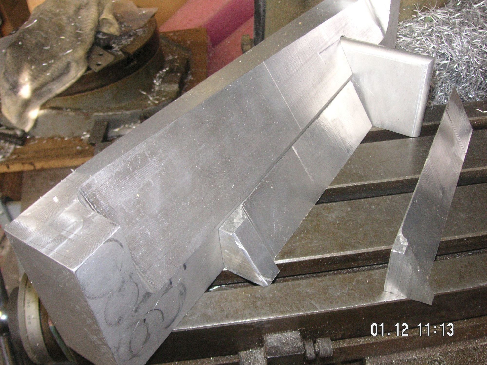
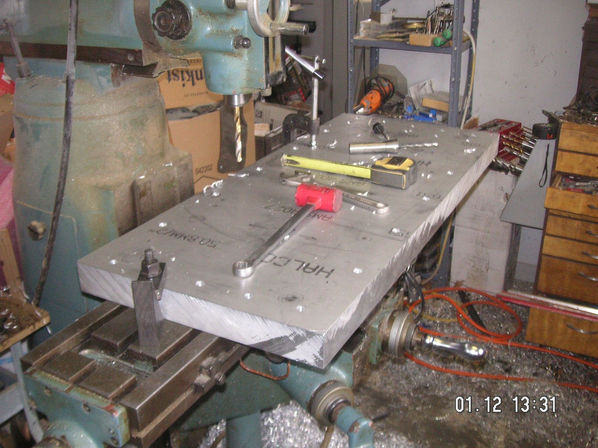
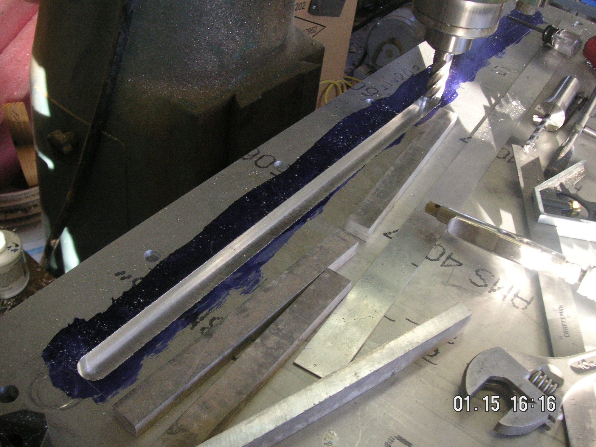
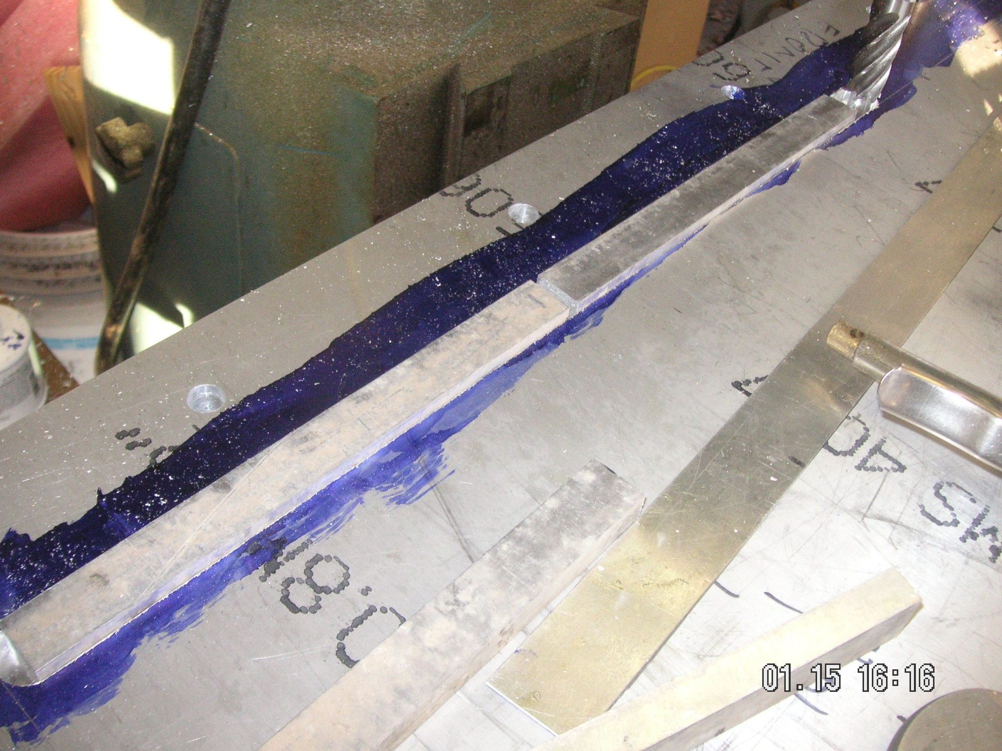
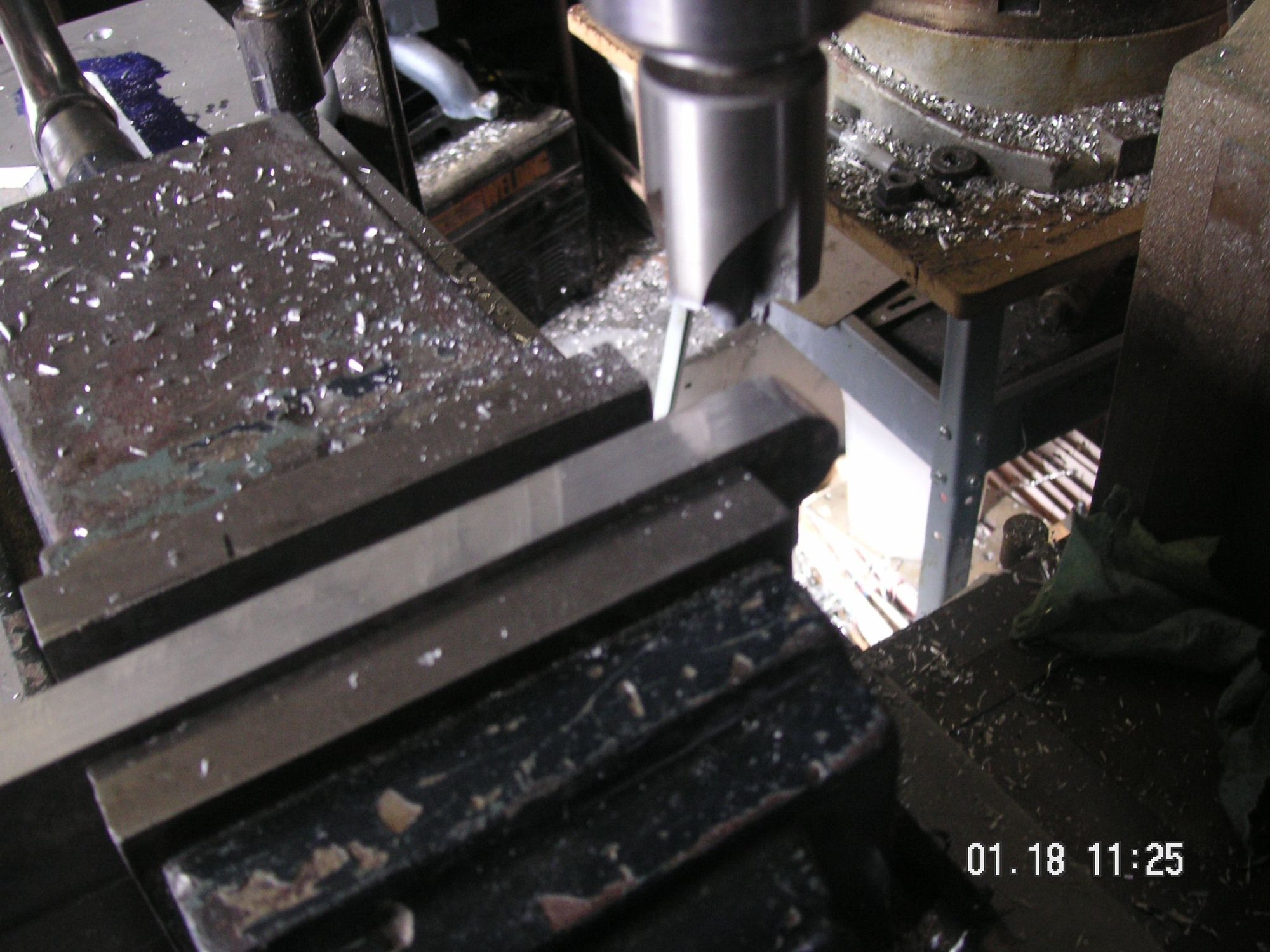
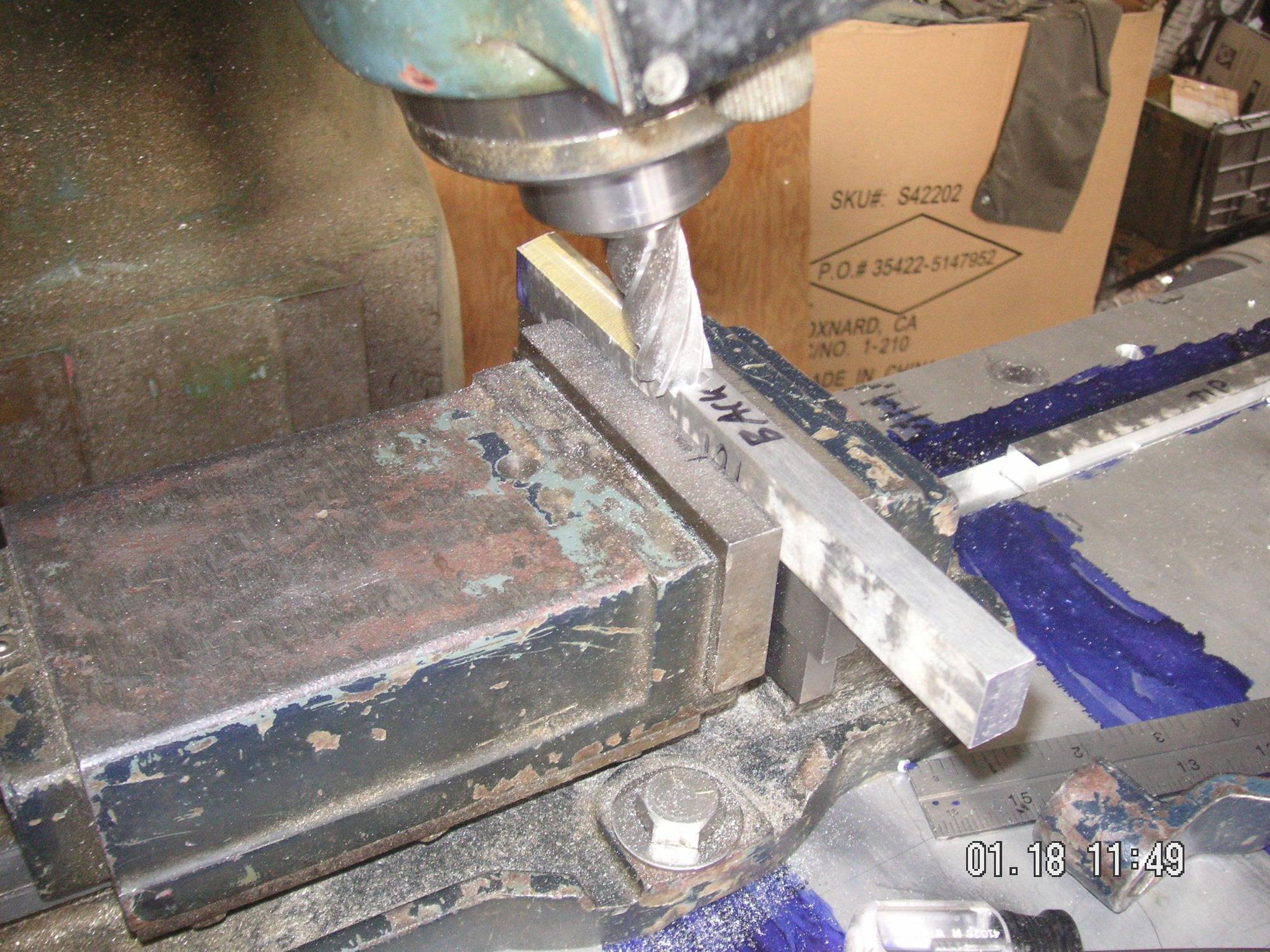
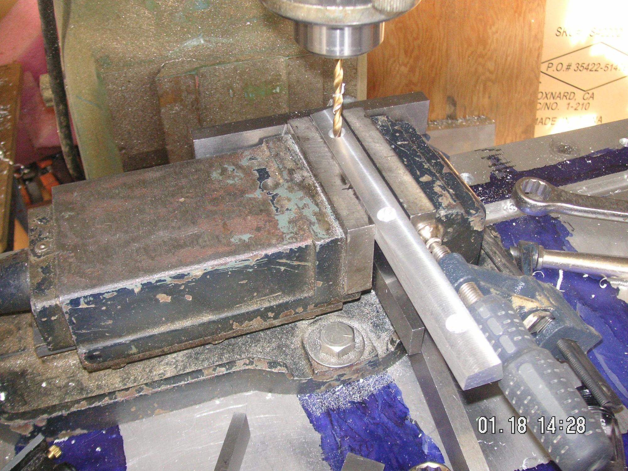
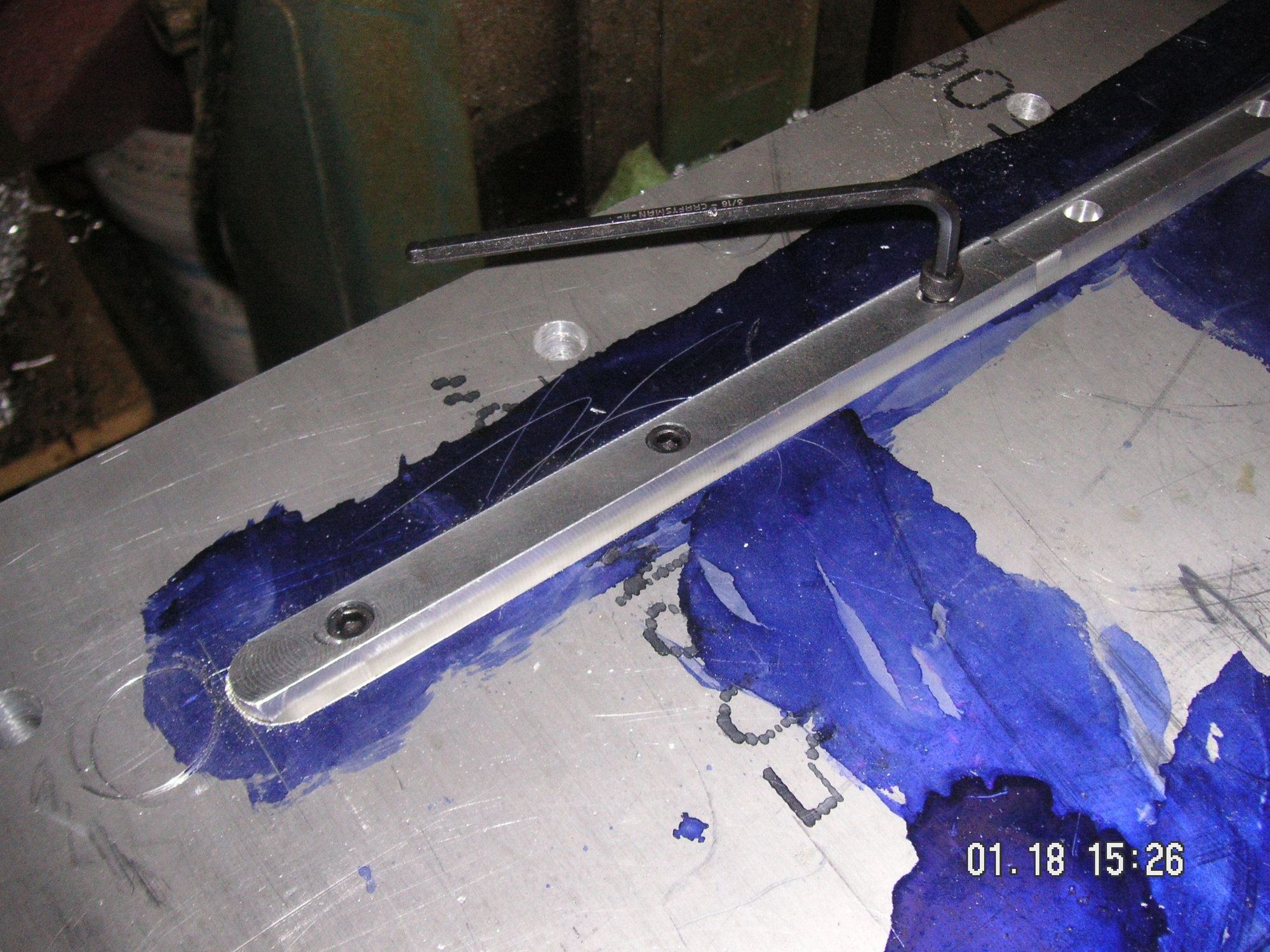
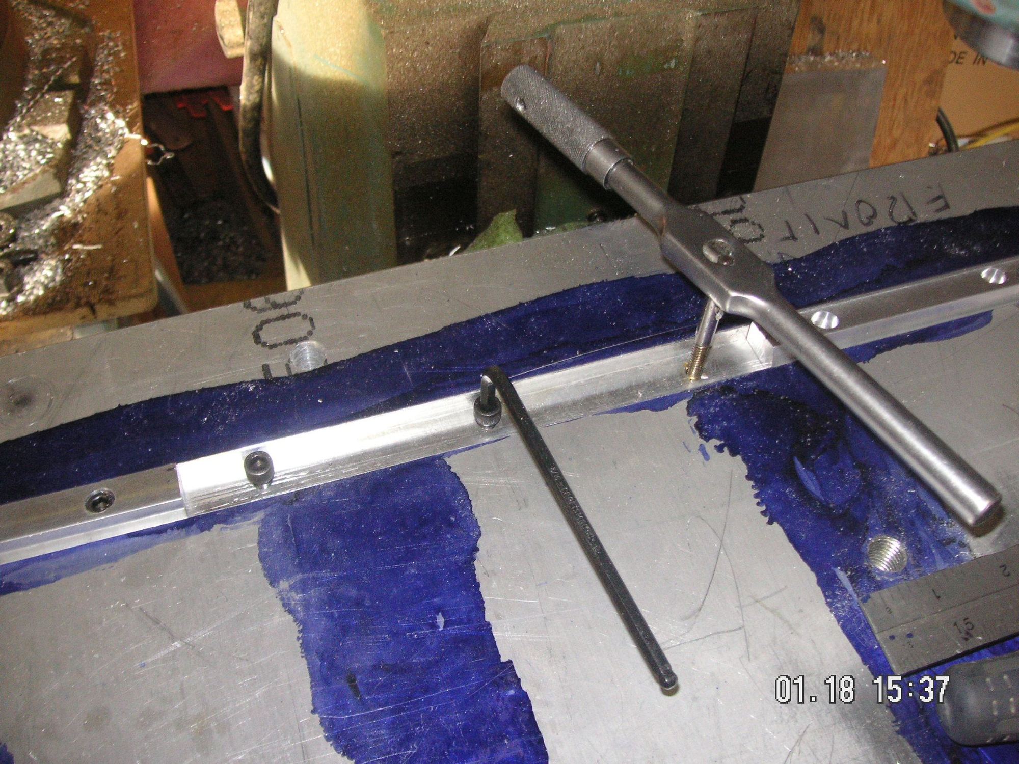
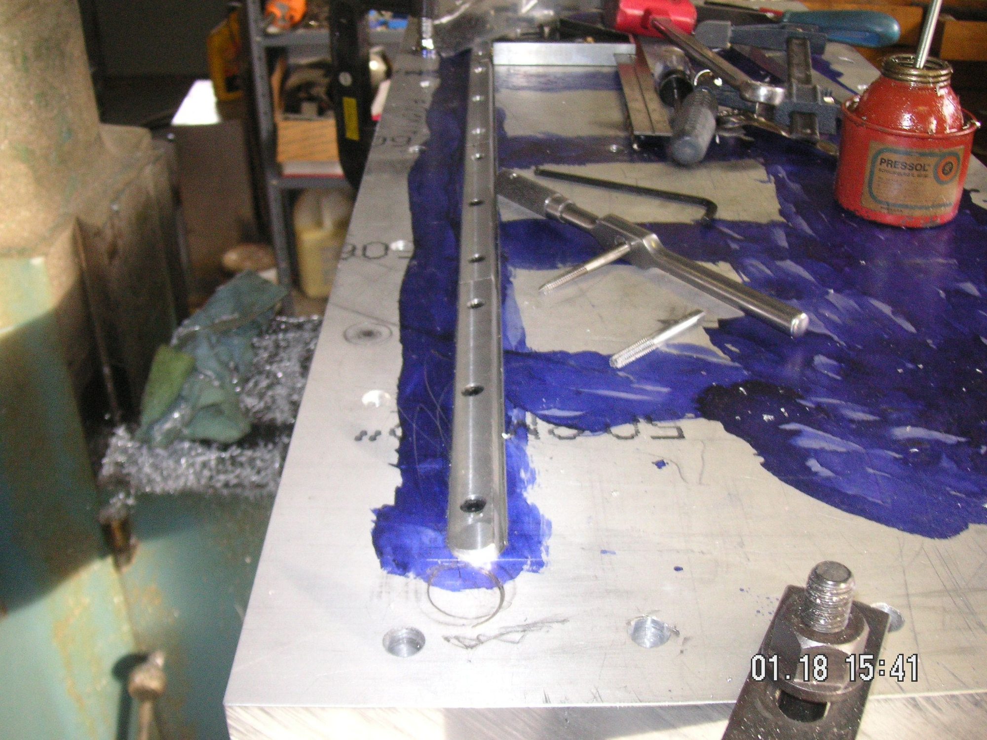
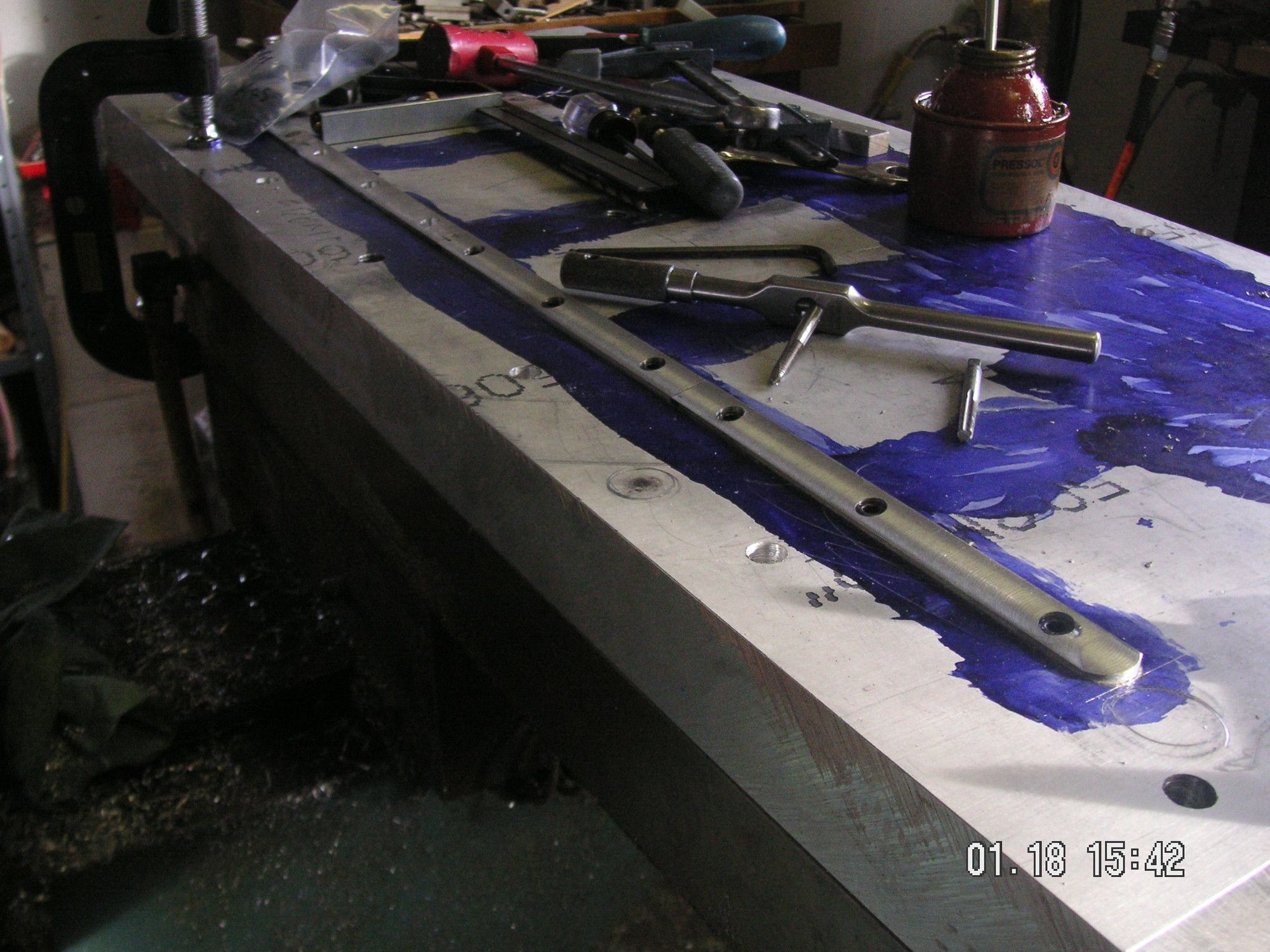
Here is a little bit more on some details. I drilled and tapped an extra hole in the base form plate that is still clamped in the mill and then bolted my mill vise to the plate. Then I finished the ends of the four form pieces that will be forming the front channel of the pan. Then I milled the back and top surfaces to the angles I want them to finish the pan at. Now I just have to bore some holes in them to mount in the base form plate slot and the counter bore the holed for the heads of the socket head bolts I have for that. I'm taking a break right now and will get back out to do the holes shortly. When they are done I can remove the mill vise and then locate an drill and tap the matching holes in the base form plate.
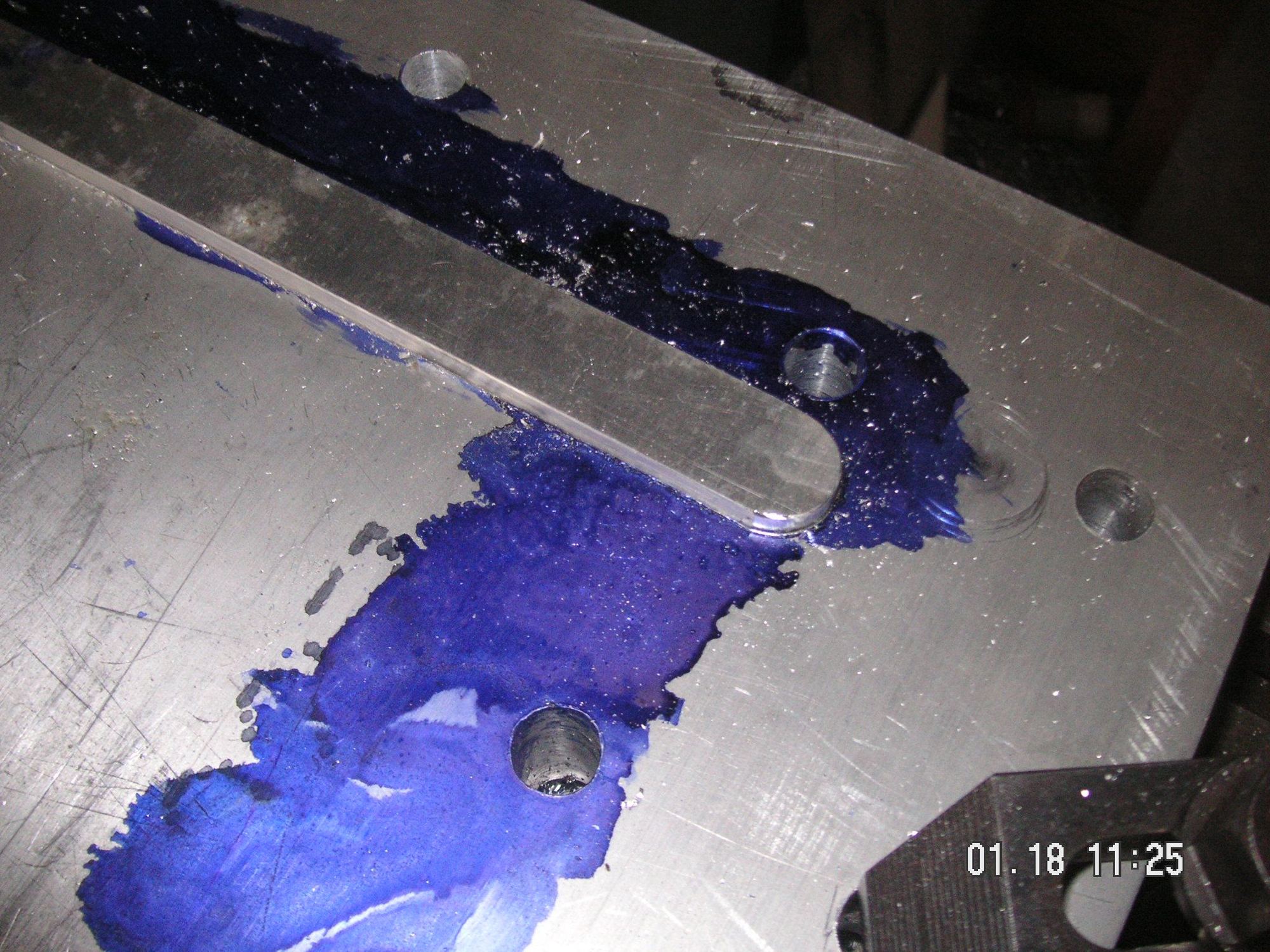
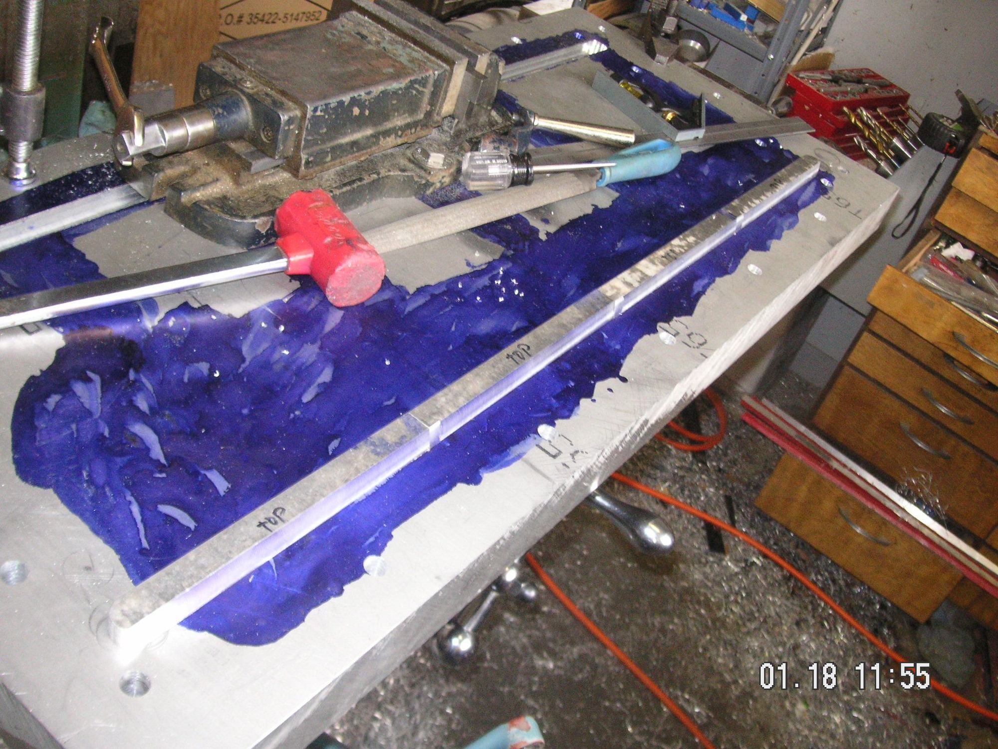
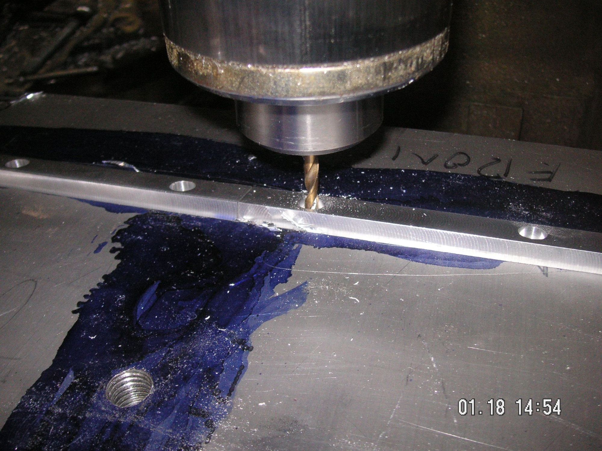
Next, you can see that I have put some Dykem on the base plate. That is ts so I can put the layout of the next slots and such into it so I can start milling those. I hope to get to much of that yet today.
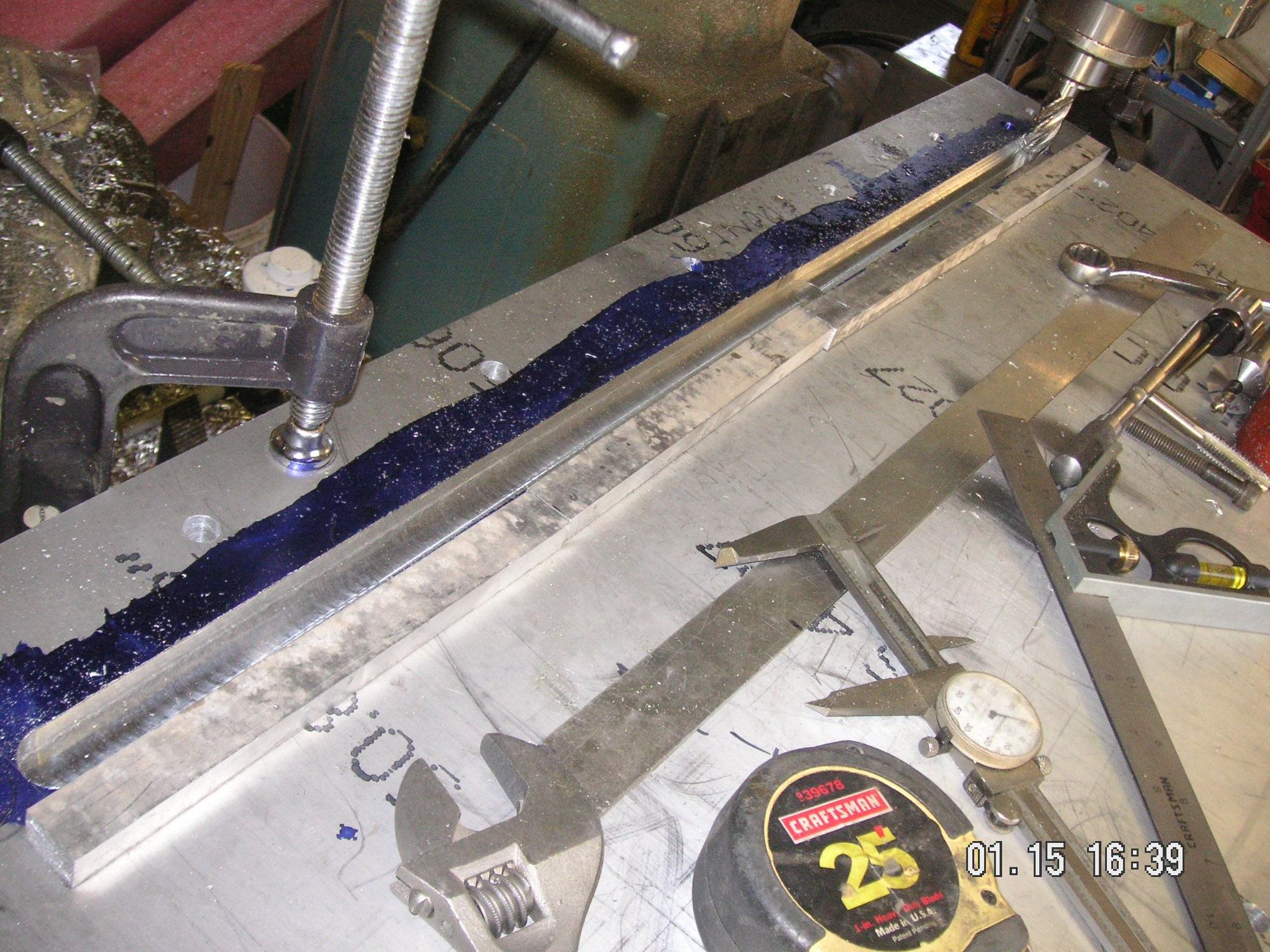
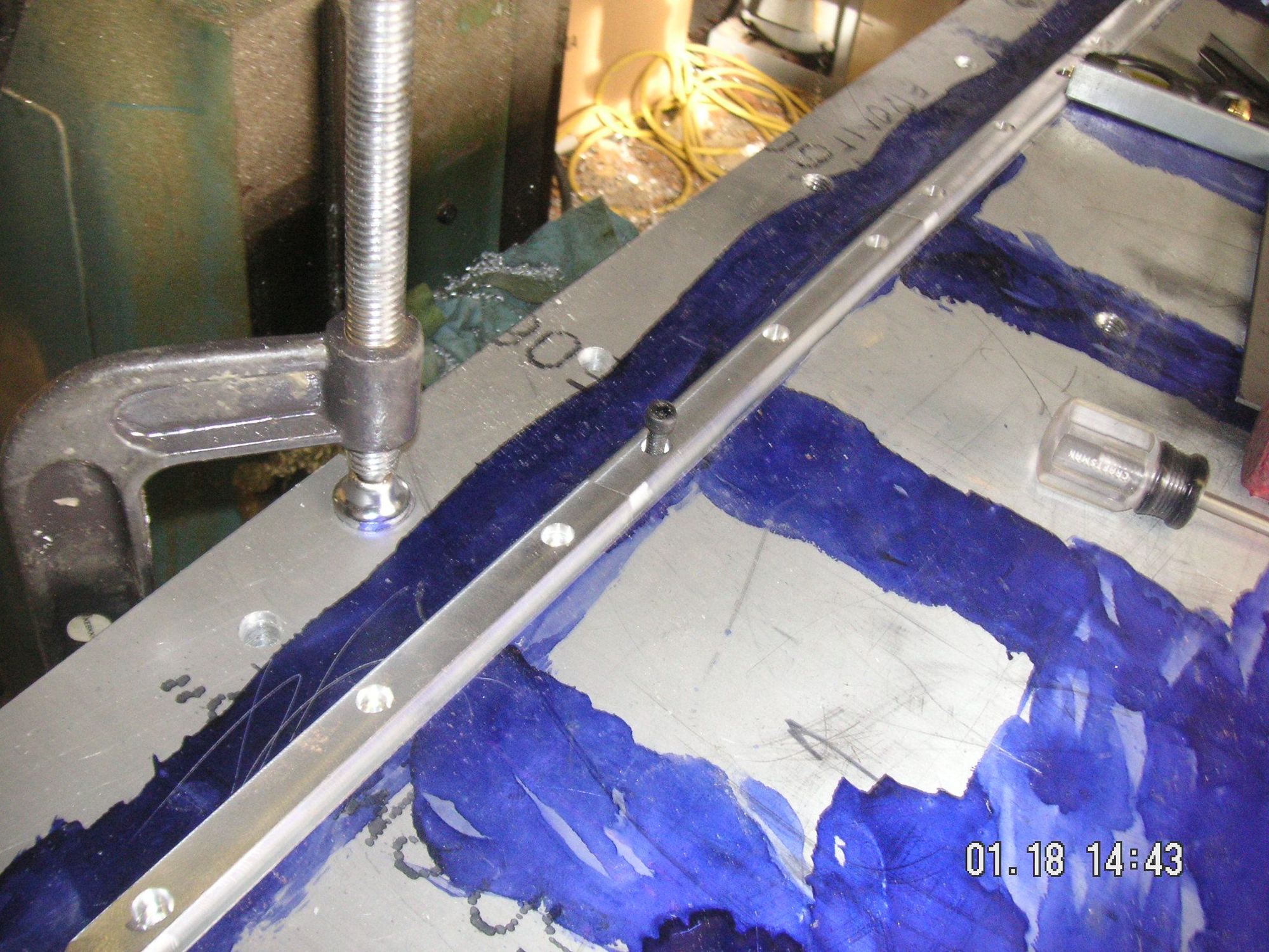
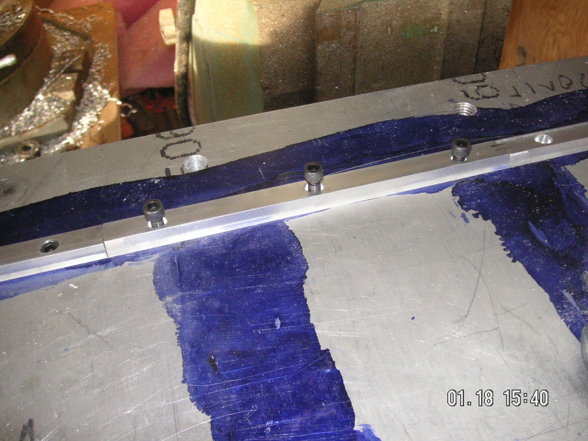
A little or lot more time and I have the form pieces formed and in place for the front channel. All it needs is for me to tap 6 more of the bolt holes. One thing I have discovered is that I changed the angle of the top surface of the front channel based on more careful measurement of the one in the pan I'm working from, and the result is that the form pieces fit a litt too deep in the slot. What I'll do is simply shim the fornt pieces up an amount sufficient to form the channel the way it ought to be.
I had hoped to get the overall layout done on the base form plate, but I guess that wil wait until tomorrow.
I work in a heavy stamping facility. I take care of the presses themselves. However, I know squat about the construction of the dies that go in the presses.
Good stuff here.
I work in a heavy stamping facility. I take care of the presses themselves. However, I know squat about the construction of the dies that go in the presses.
Good stuff here.
In spite of what you say, Seth, you probably know more about what I am trying to do than I do. However, my forms are more related to pressing than stamping. The difference, of course, is in the time it takes to do the actual forming of the sheet metal being formed. I doubt that my forms bear any resemblance to the kind of forms used in your stamping facility.

 01-10-2020, 08:51 PM