When you click on links to various merchants on this site and make a purchase, this can result in this site earning a commission. Affiliate programs and affiliations include, but are not limited to, the eBay Partner Network.
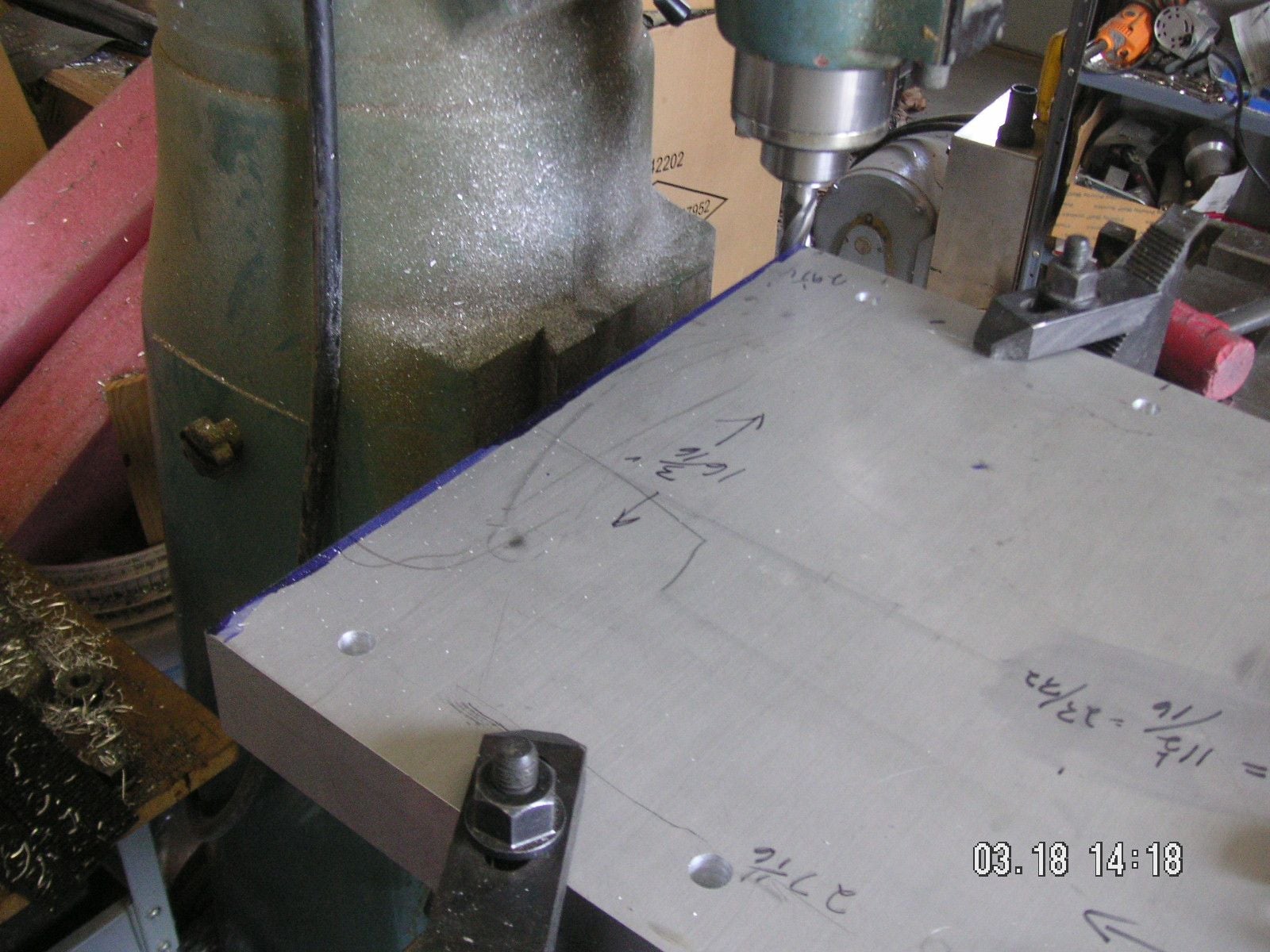
I cleaned off part of my work table and the top of the bottom plate in the mill and then got it moved from the mill to the table. I temporarily bolted the two end plates to it for fitting of the center top plate and then marked the end of that plate for a refinement to the edge which was slightly off. I milled that true and then put it back onto the bottom plate and find that the other end of it also needs to be trimmed. I also tapped the last four holes in the base plate and then opened up the pilot holes in the top plate for the half inch bolts that will be guides and then bolt the two together to hold the forming metal while the ends are being formed.
Now I need to trim the other end of the top plate and then start the task of locating all of the form pieces I have been making to bolt carefully into position on the top plate I don't think that will take too long; and then I'll be ready for the details on each end.
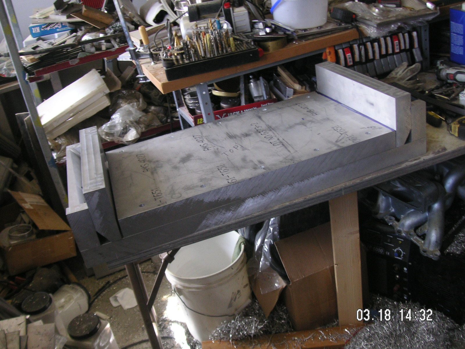
I find that I can barely lift the center top plate, so it is less trouble to put it into and out of the mill. The bottom plate is a different story.
Last edited by Jerry Feather; 03-19-2020 at 10:55 AM.
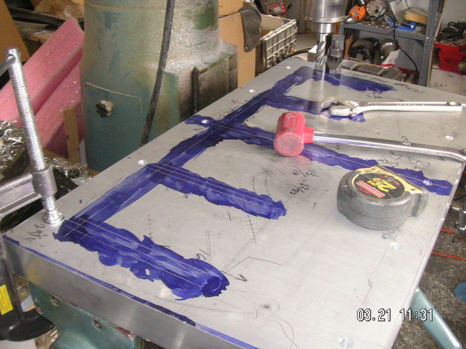
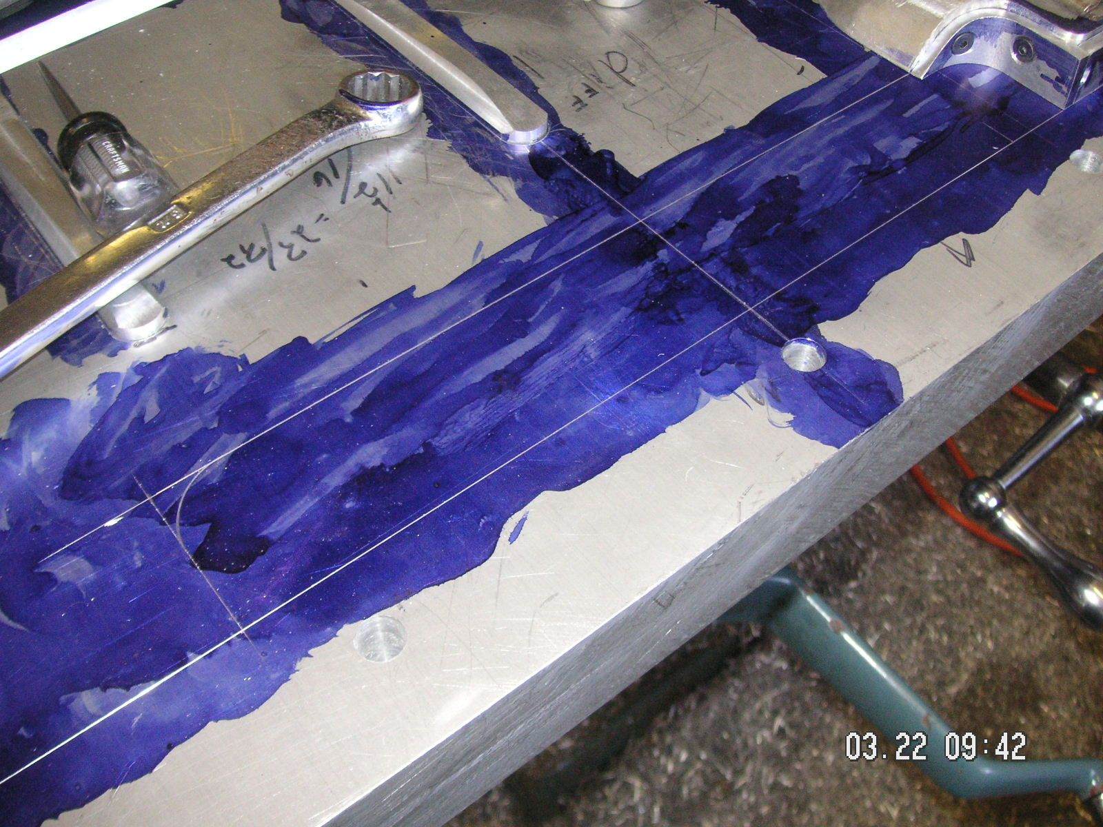
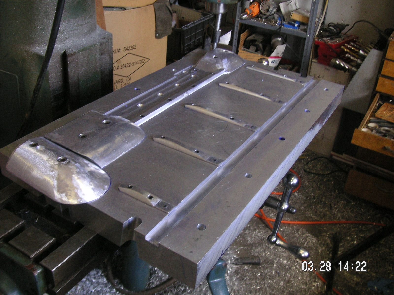
I trimmed the other edge of the top plate so that there is clearance for the metl being formed and for some spacer material to keep the end forming plate tight depending on the thickness of the metal being formed. Then I drilled and tapped the top plate for some barn door handles so that I'll be able to handle it a bit mor easily, They help but do not make it any lighter. Then I turned it over and layed out the front channel and the groves for the 5 ribs. Those came out pretty well. I have to locate the bolt holes for mounting the f=rib forms, but I think I can do that with them in their intended locations rather than having to put the mill vise back in the mill to hold them. I think I'll drill and tap one hole for each rib to hold them in place and then do the second hole for each one.
I determined that the groove along the front of the top plate for the front channel of the pan needs to be a bit wider than the 3/4 inch I made it, to allow for the thickness of the metal being formed. So I miled that out a bit; then I had to move the rib forms back a bit equal to the extra width of the groove.
With that I still have to drill the rib forms and tap the holes for them to mount solidly, and I am still cogitating just how best to do that without having the mill vise readily available.
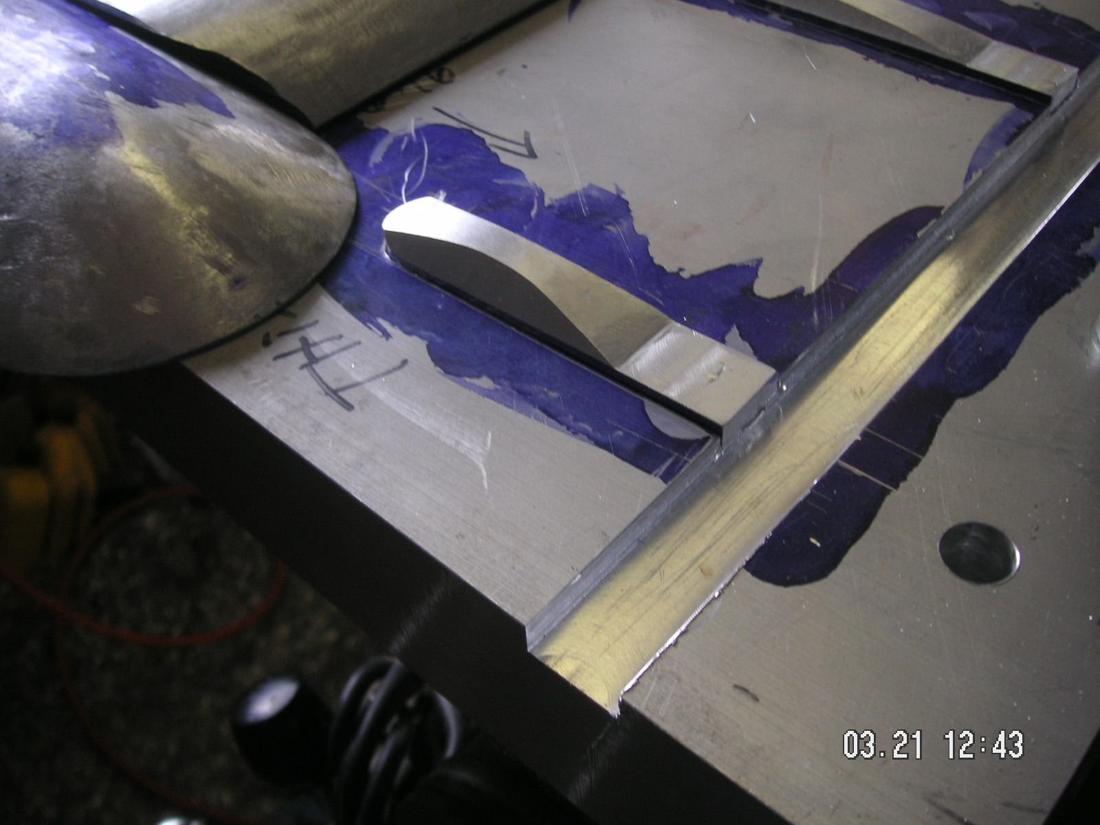
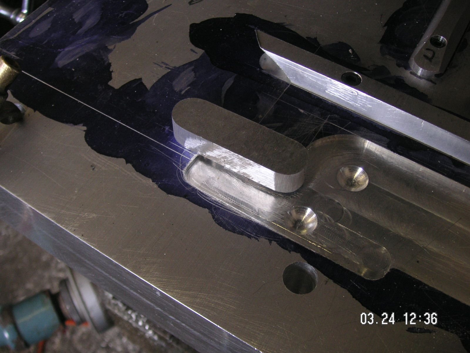
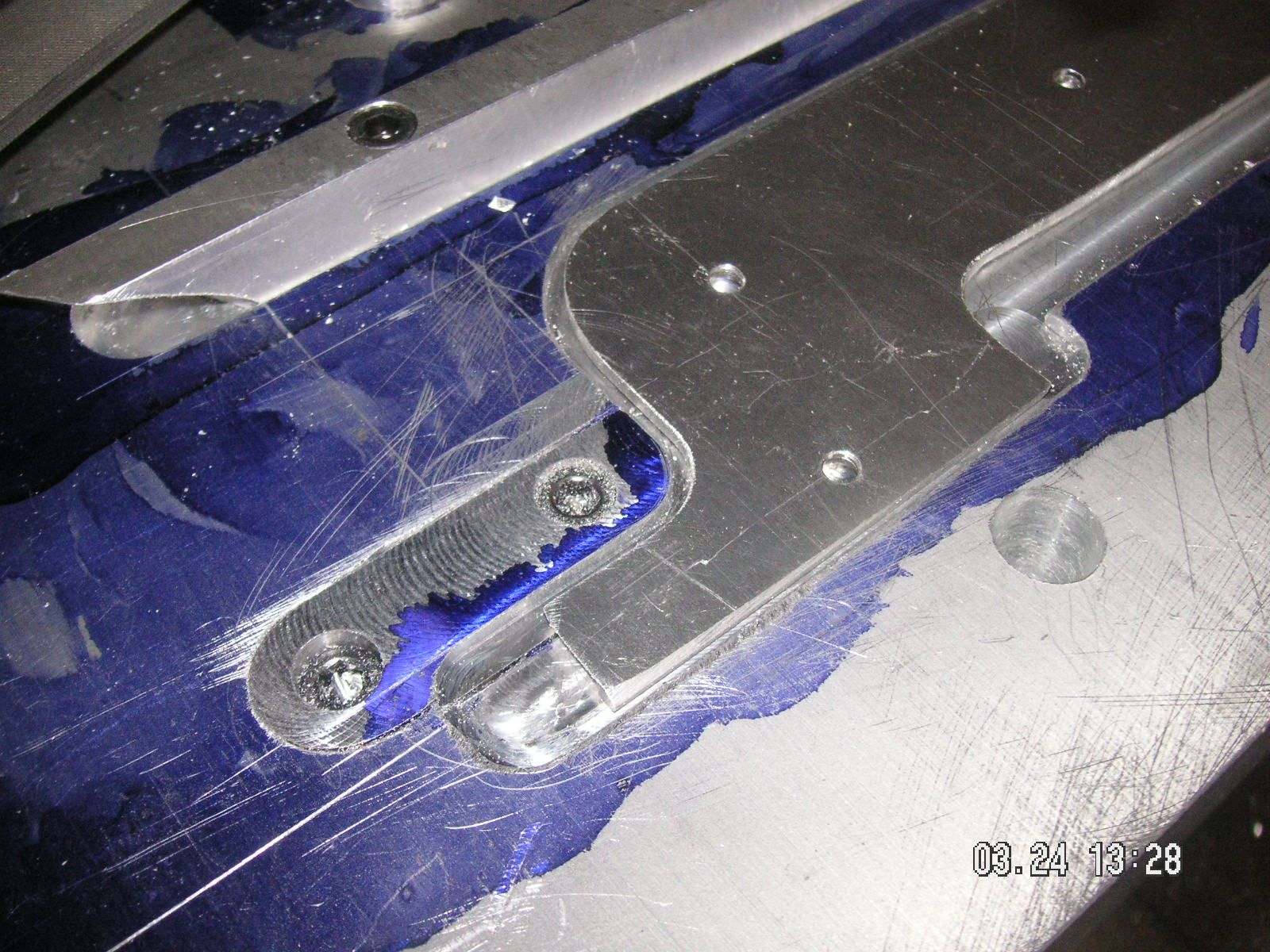
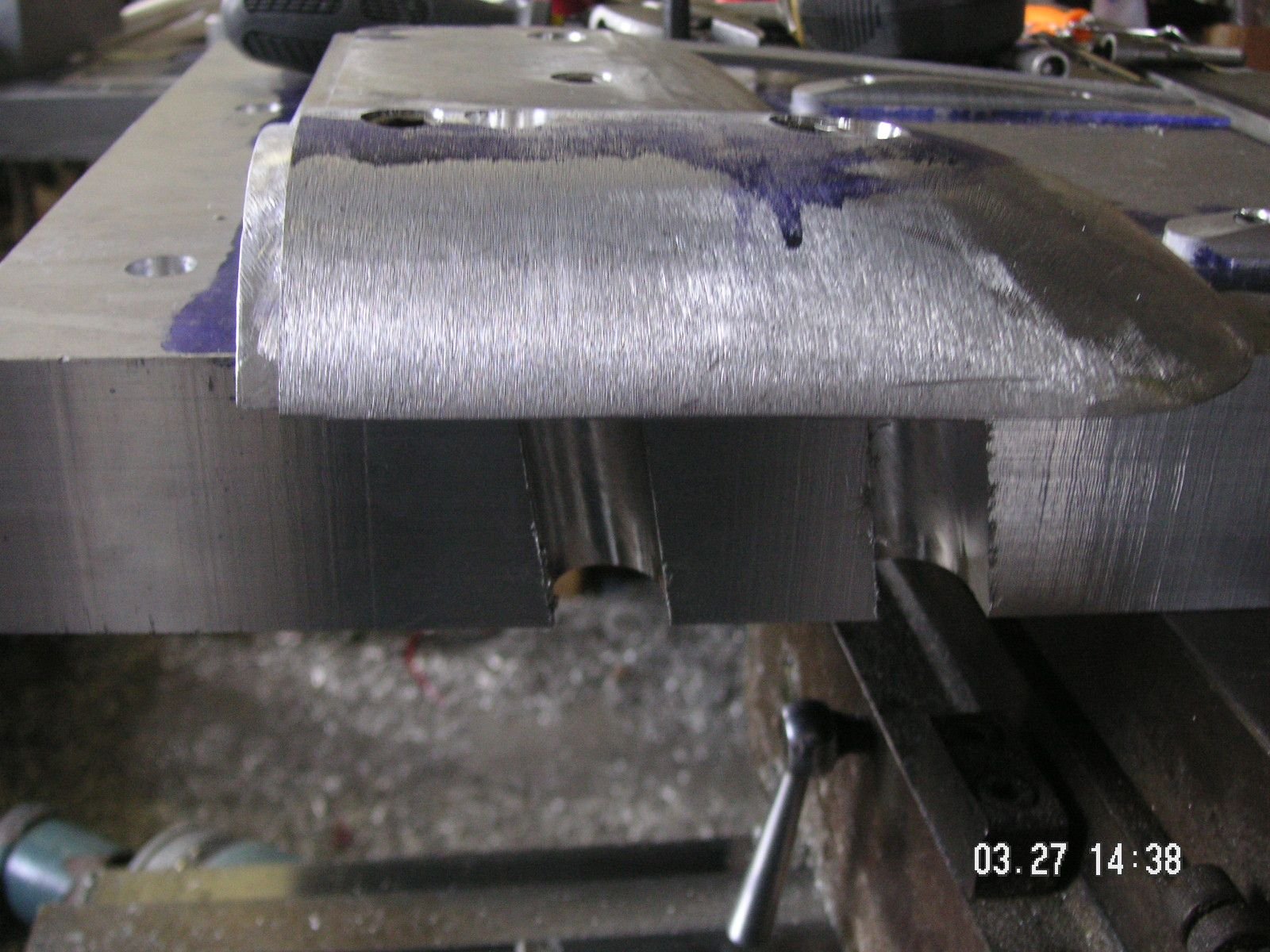
Then I milled the recess for the rear center form for the trailing edge finish I'll designing. that came out pretty nice. I included recesses in it to allow for the screw heads holding the male form on the base plate.
Next, after I take this break, I'm going to mill the groove for the male form that will form the crossways kind of rib just forward of the trailing edge in the center. That will nearly complete the top center plate, except for some slots in the ends to help form the front bottom corner kind of stiffening angles. That is also taking some mental effort for me to figure out just how to mil them.
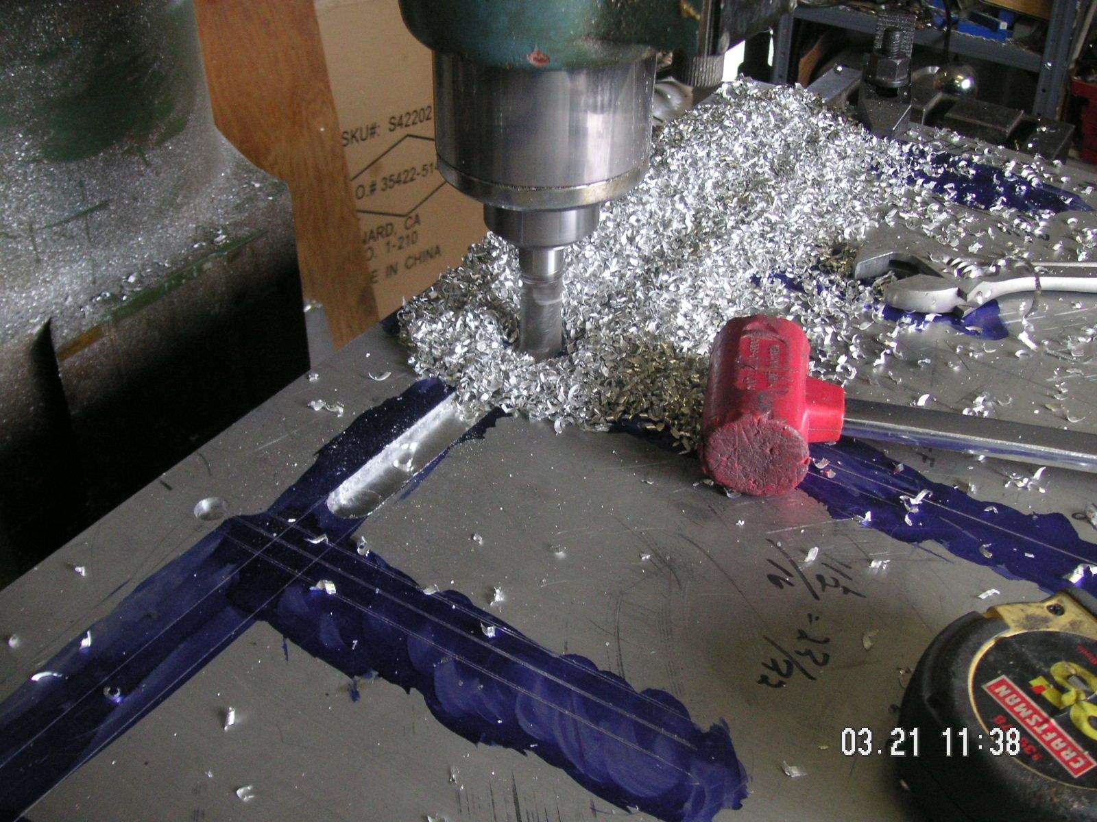
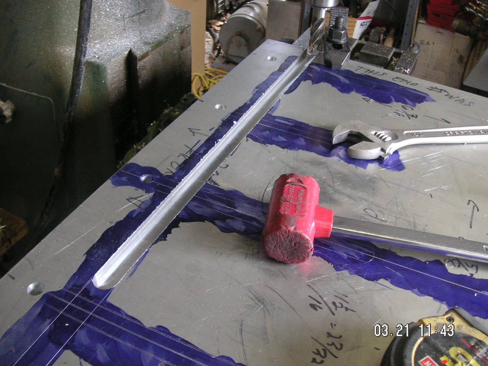
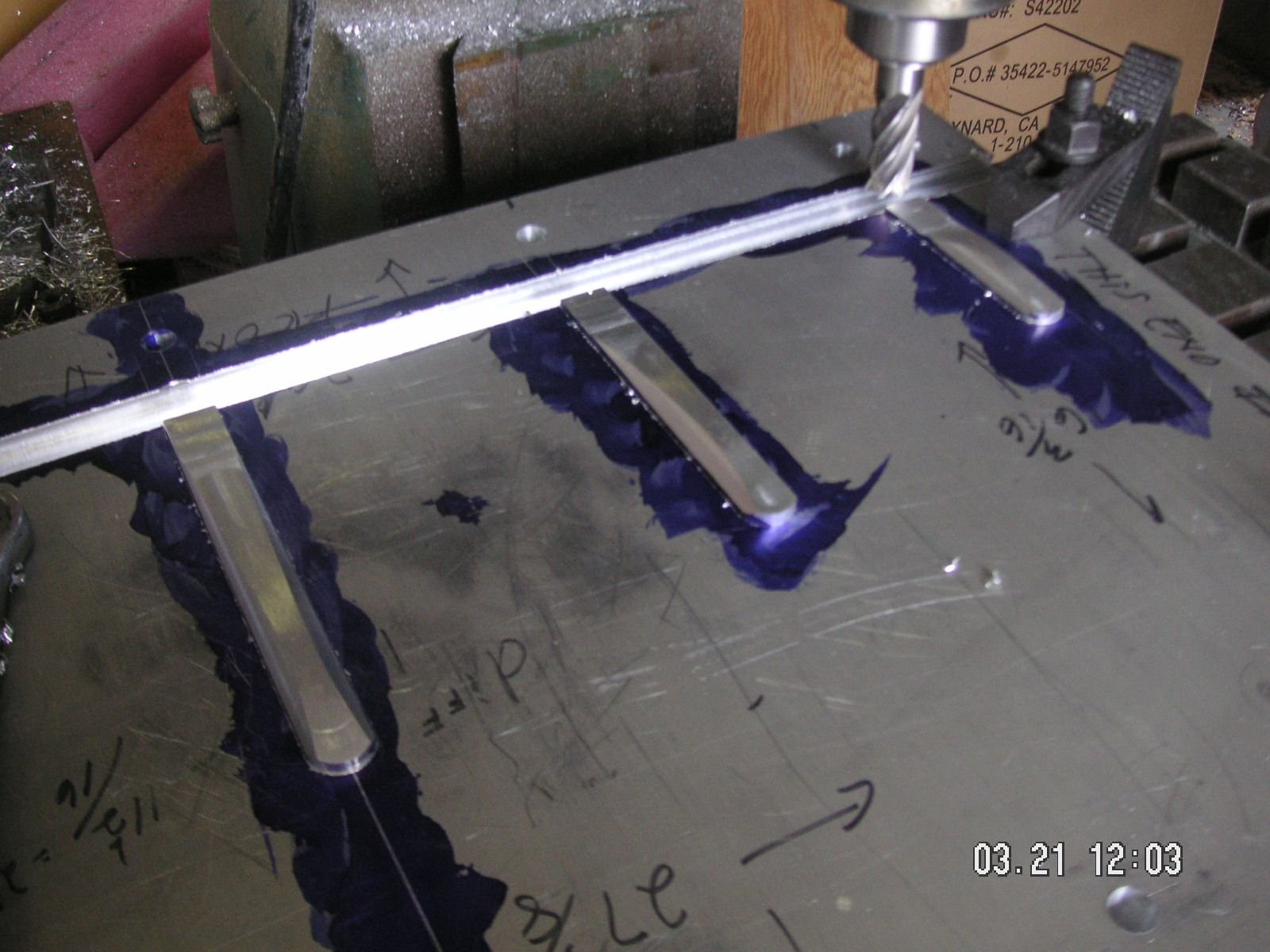
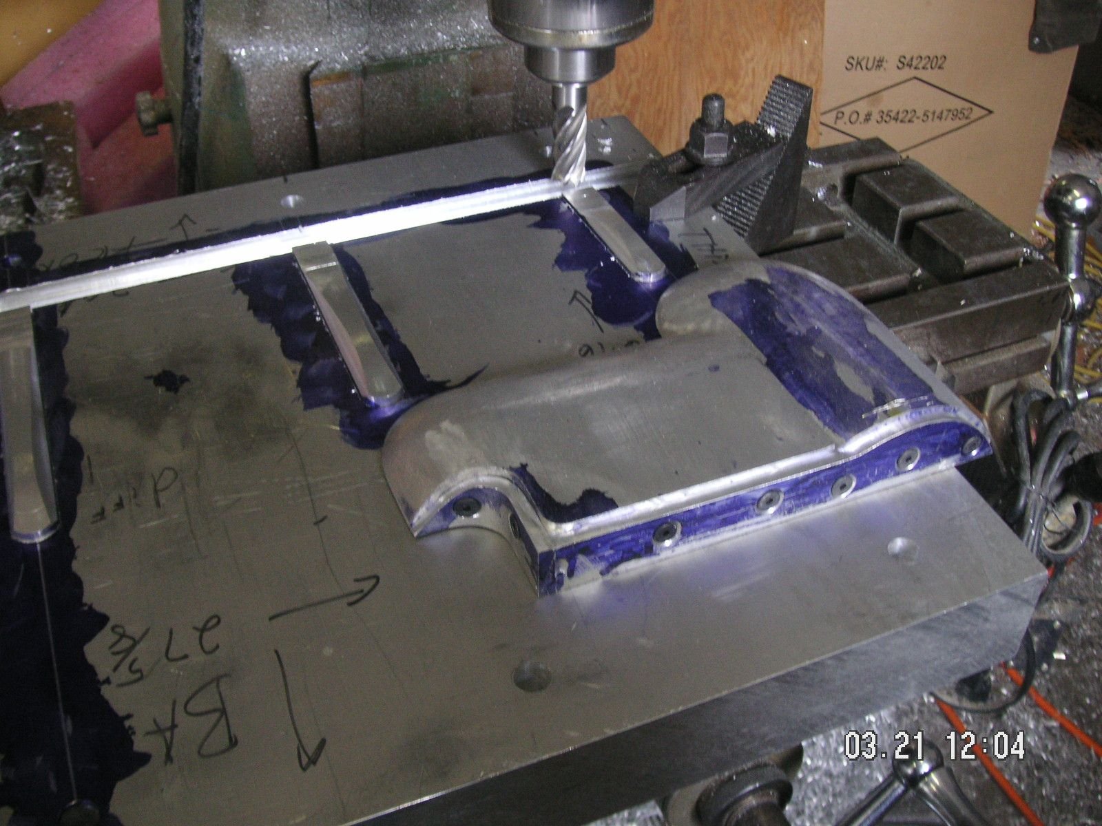
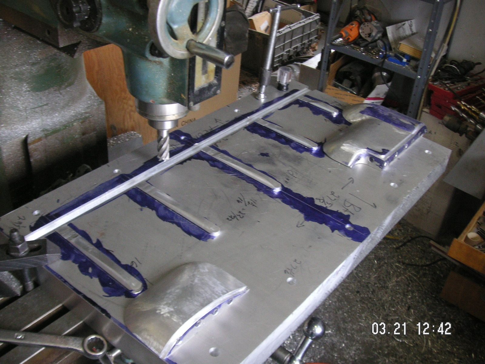
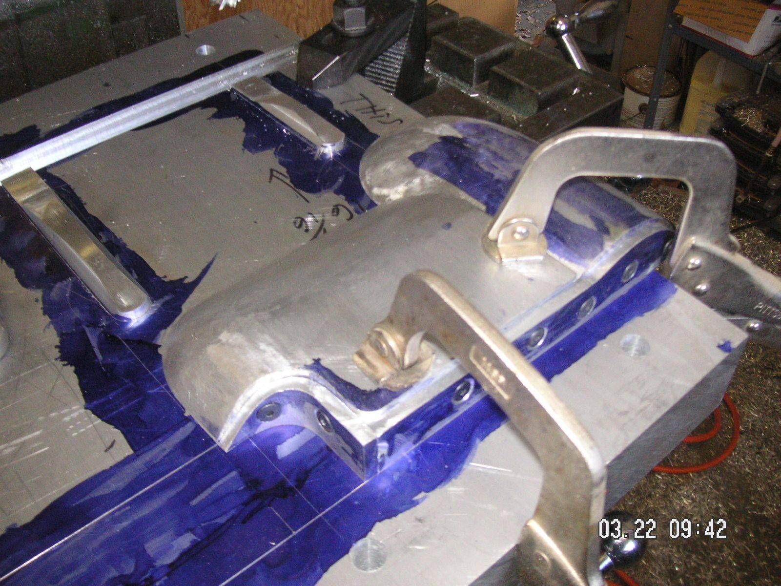
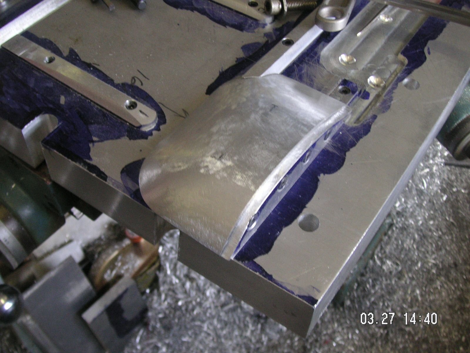
Oh yeah. I still need to mount the two major bulge forms, but that is turning out to be less of a measuring exercise than I had anticipated. I'll have that done shortly too, I think. You can see that I have one of them temporarily clamped in place at the lines I made.
I got the crossways groove and the male form that goes in it complete, including the bolt holes drilled, recessed and tapped. Now I need to be sure of the location of the two major bulge forms and drill them for permanent mouunting. I also need to drill the rib forms; but now I need to go out for some driving since I am teaching my daughter how to drive, and we are doing it in y truck rather than one of the cars since that is to only one I have insurance on for anyone but me. For the rest of my cars I have what is called broad form insurance, which insures me rather than the car, and it is only for liability. I am basically self insured f
or any collision damage. I'm counting on it being the other guy's fault and that he has good insurance.
Yesterday I finished up with the bolts and holes to hold the rib forms down, I still have to locate and place some very small threaded holes in the parts of the rib forms that form the recess for the front mounting holes into which I can put some small round head screws simply to mark the formed pans where to drill the front row of mounting holes. I think I have figured out a good way to do that. I already have the matching holes in the bottom form as recesses for the marks.
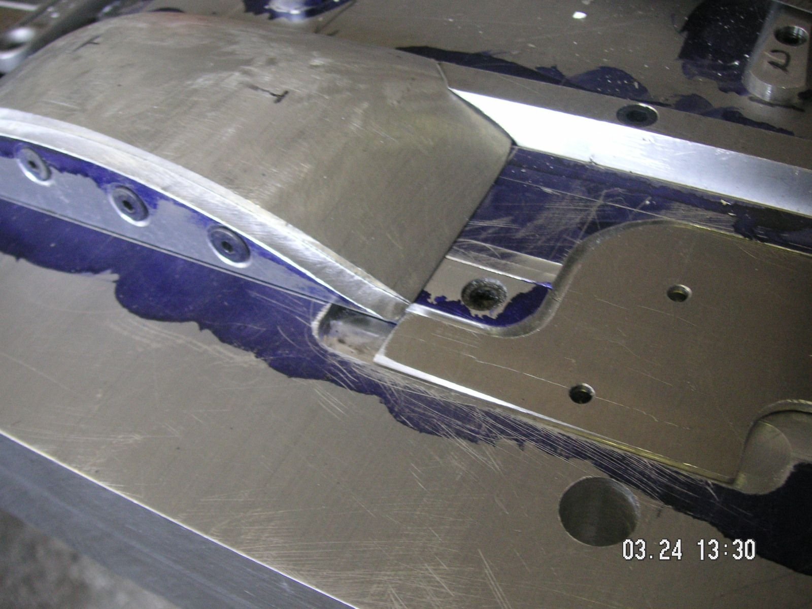
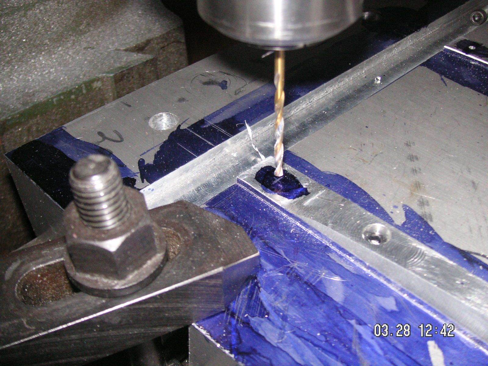
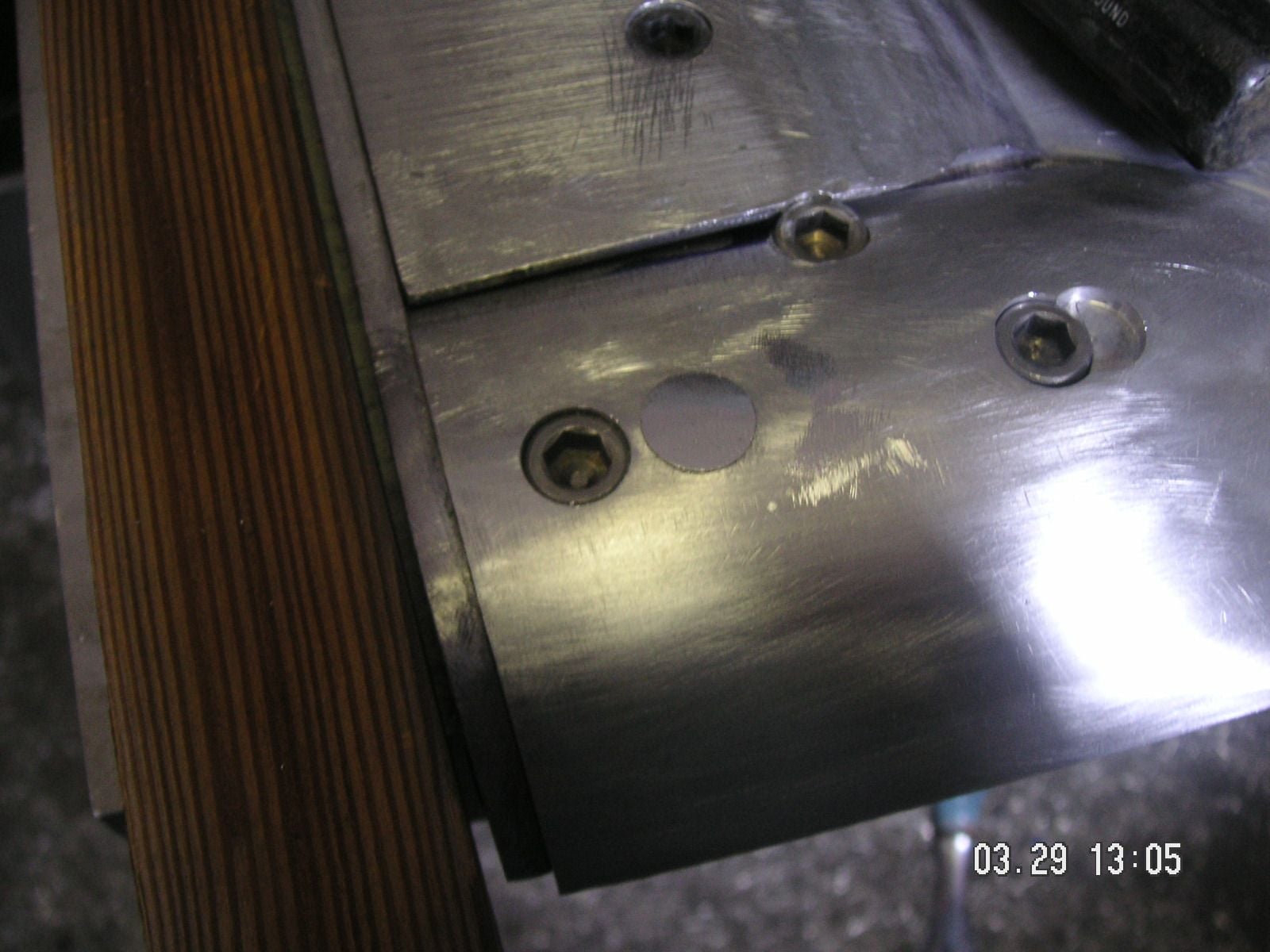
Then, I found a mistake in the recess I milled for the center trailing edge. It took me a while to figure out just what the mistake is, but you can see it in a couple of the pictures above. The first picture on 03.22.13:31 and then again at 14:31. The mistake jumps out at me, but I could not figure out how I made it or how to correct it. You may not be able to tell what the mistake is. To correct it I am going to need to mill out a 3/4 inch groove a half inch deep in order to bolt in a supstitute piece of aluminum that I can mill correctly.
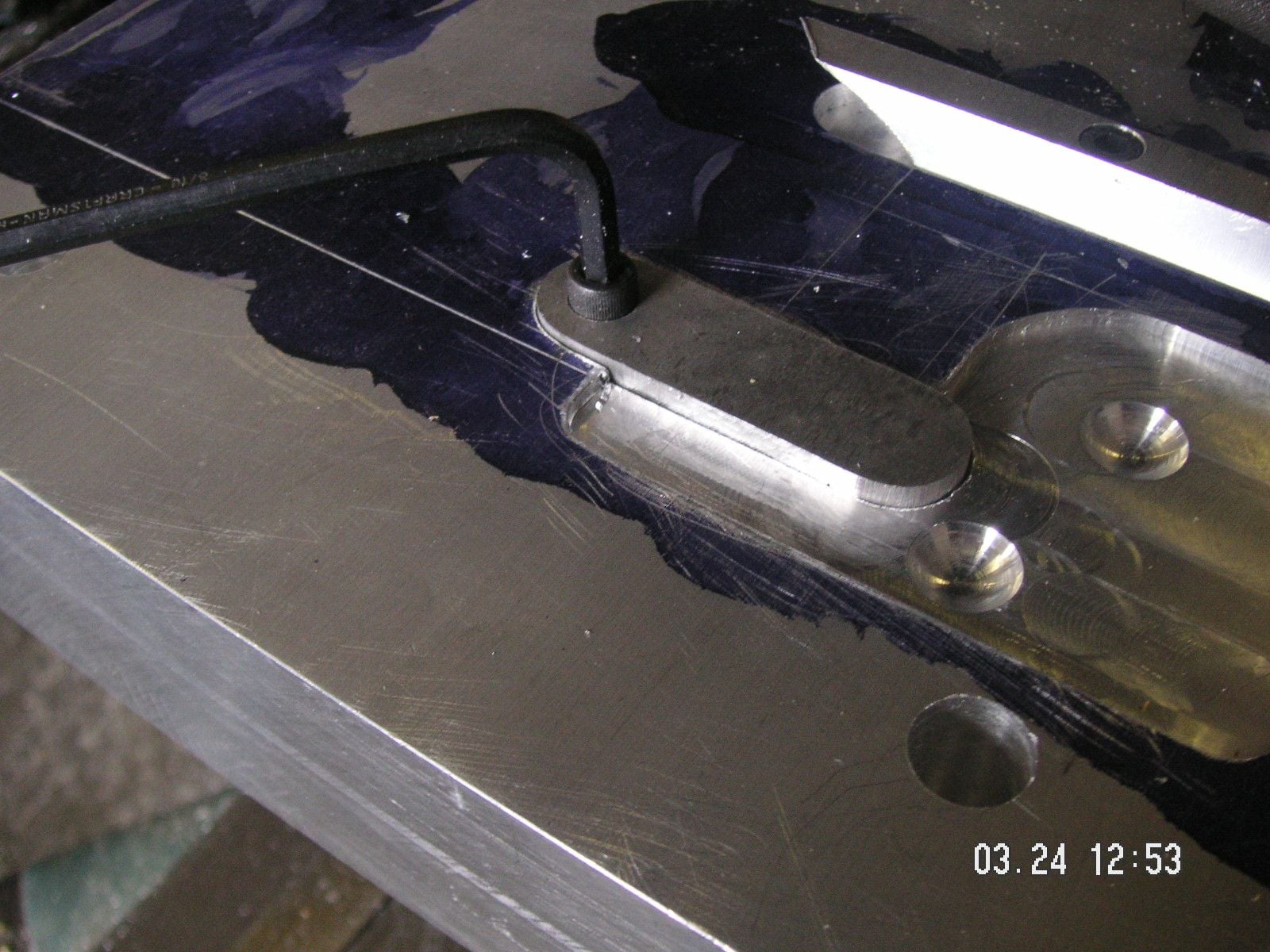
Well, it took me a little over an hour to correct that mistake, and even at that I misssed it again by a few thousandths, but not enought to need to be corrected again. Now it looks like it ought to be there.
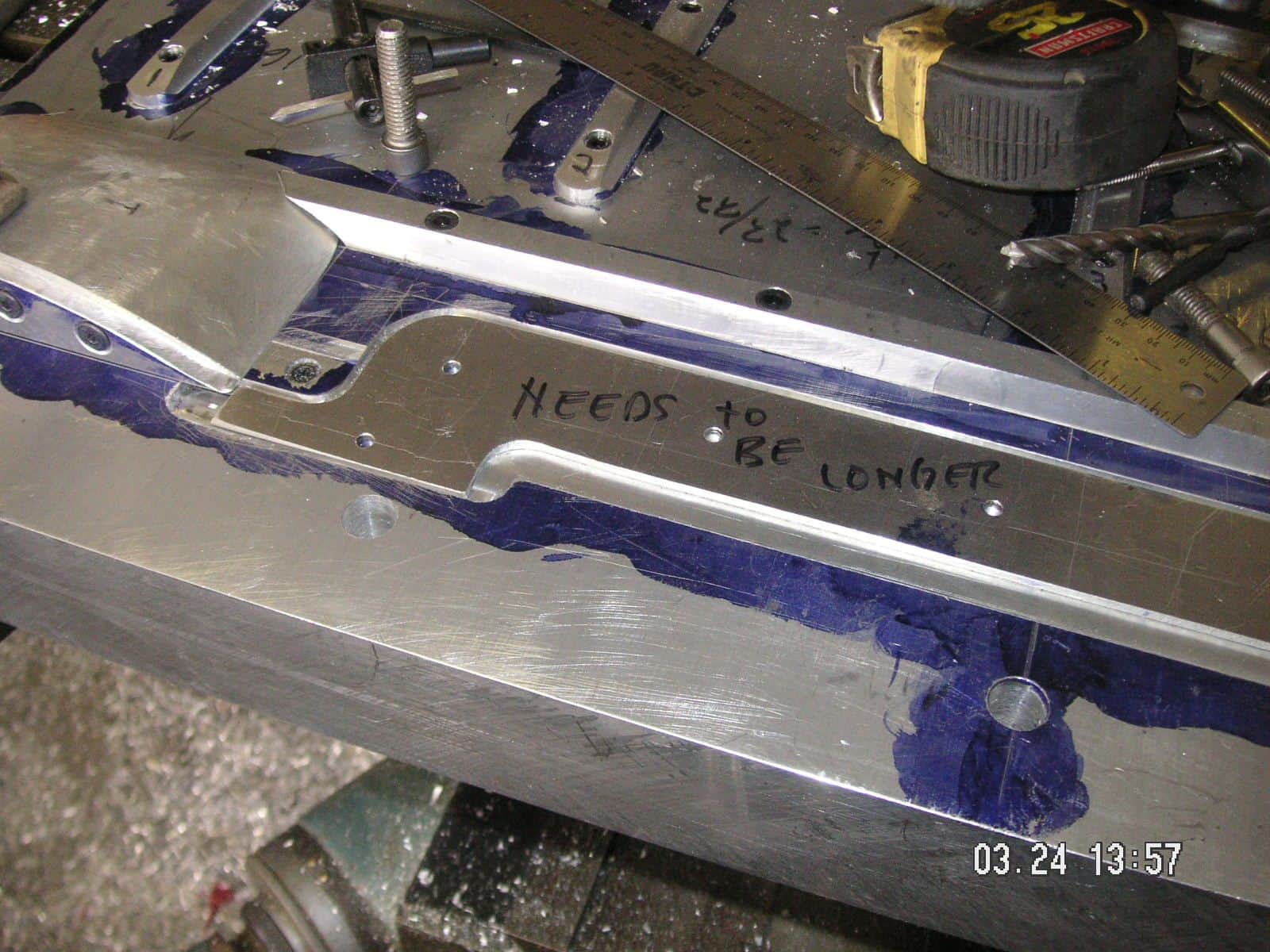
Actually it probably does not need to be longer. If so, I can do it later after I try forming with it this way.
I was going to drill and tap the two bulge forms onto the top pate, but I want to use 3/8 inch bolts so that I don't have to use too many. I'll use socket head bolts, but I find that the head of the 3/8 inch bolts is over a half inch, so I cannot counter bore for them except with a 9/16 inch mill bit. I don't have one. Go figure. I ordered two of them on eBay and they will probably be here by Monday, or even Saturday if I am lucky. I could have changed to 5/16 inch bolts but then I think I ought to use more of them, and I don't want to for some reason. The counter bore holes for the bolt heads will remain open, but I think the metal will form over them without being very noticable in the formed metal.
In the meantime I can finish up the top plate with the little screws to mark the mounting holes along the front and then cut the slots in the left and right edges of the plate to help form the three angle braces being formed into the corners. I can also start doing some detailing of the base plate to round some of the corners and soften some of the edges where I think the metal being formed might have a tendency to break. I can to that with the plate on the work table and I will do it all by hand with my disc grinder, a file and some sandpaper.
This project is taking about as long as I thought it might, but I'm sure many of you might think that it is too long. I have been working in short periods of about ah hour and a half to 4 or even 5 hours, once in a while, but I find that since essentially all of the plans for this are in my head, with only a bit of it on paper, I have to stop at frequent points to rethink ahead about what and how the next thing must be done. When I push it too far ahead is where I end up with the mistakes. Nevertheless, I am trying to stay fucused on this project since if I were to abandon it for any significant period I run the risk of losing the plans in my head and I would have to kind of start over. At this point I think I have too much invested in this projedt to let that happen. I'll keep on keeping on.
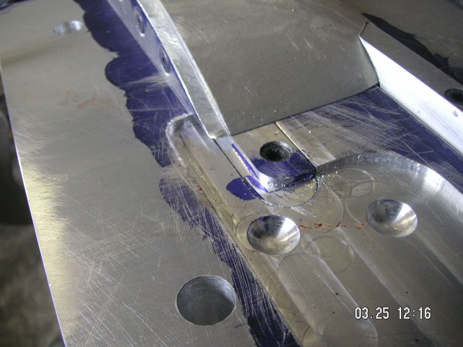
I decided to redo the patch, so I made a new one and finished it off almost perfectly. The first one was about 15 thou off and the new one is less than 5 off. I can live with that; and I didn't like the adjustment I would have needed to make to live with the first one.
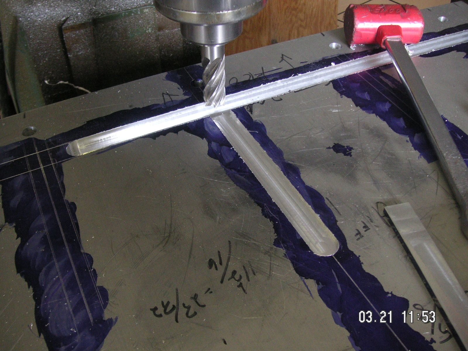
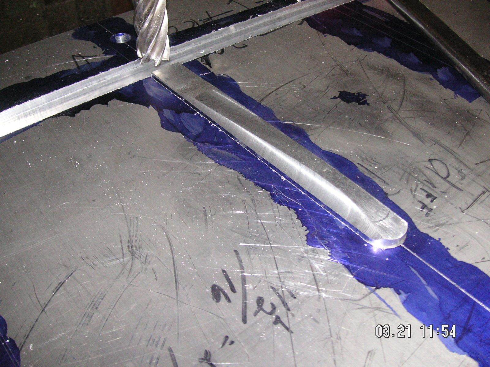
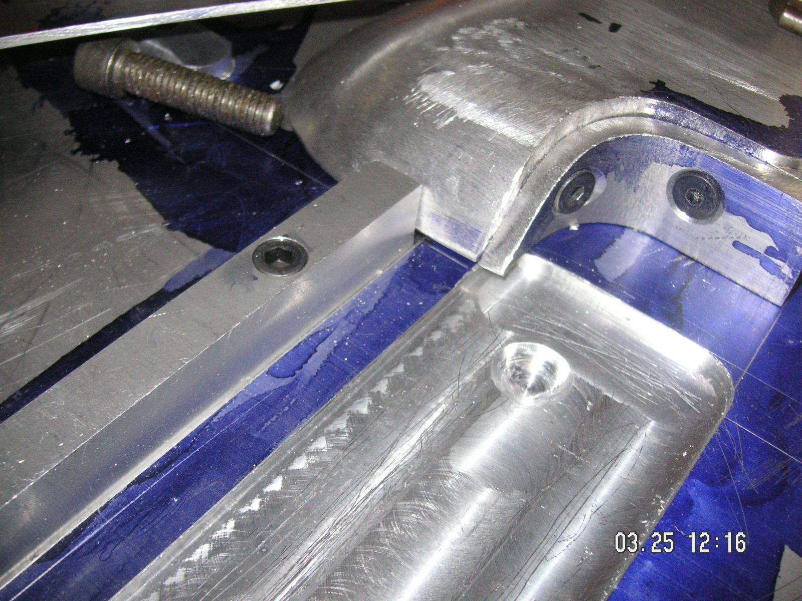
Then I took the top plate loose and rotated it so I could cut the slots in the ends which will form the rim around the corner braces. Then I forgot that I was working on the plate upside down and milled the first slot at the opposite angle. I had to mill it correctly, but on the form side the opening is the same. The slot slants 9 degrees and I am planning to use the slots as sort of guides to get the end forms to follow them in forming the ends of the pans. I may still be able to do that, but if that doesn't work I might just put another slot in the end of the form just as a guide.
In fact, the more I think about it and the problem of using a 50 ton press, which pushes straight downward, but with the need for the form being pushed downward to also move one way or the other at the 9 degree angle, the more I think I may need more guides than just the two successful slots milled in one end and the double angle slot at the other end. I think what I ought to do is mill one more slot in the good end and at least two more slots in the other end. I was concerned about what the extra slots might do in respect to the metal being formed, but then it finally occurred to me that I can put the extra slots at the location of the bulge forms and they will not beforming any metal since the metal under them will have already been formed by the bulge forms. Voila!
Yesterday was the first day of what I think is a state wide Governor's Executive Order for everyone to stay home, except for various essential kinds of things. There is no deffinition of what is essential except for things like groceries and various essential kinds of work, but anyway even thought except for some grocery shopping I stayed home. Even at that I didn't even go out to the shop and do anything with this project. I stayed inside and cleaned up the kitchen and dinning room so that I could prepare a dinner for my Son and his family for and essential dinner overy here.
The other reason that I didn't work in the shop is that I have been working on the design of the next small task which is the small screws to mark the mounting hole location along the front of the pan. My thinking has taken me away from simple screws which I think would require me to counter bore so that only a very small part of the screw head is exposed to simply mark the metal when it is formed for the hole locations. Then I thought through what might happen if the tap might be broken off in one of the holes, maybe leaving a small bit protruding, and it finally occurred to me that that is all I really need is a bit of screw threaded body sticking up. So I am deciding to simply drill and tap to a fixed depth and then use some small set screws for the marks. They wont have a head so I don't have to deal with the risk of having the screw head stick up too much by counter boring, which runs the risk of shearing off a bit of the formed metal into the counter hole for the marks. Really all I need is a simple mark to see later where to drill.
I'm gong to stop at the hardware store after a bit of essential time at the office and again at the grocery store, for these essential set screws. Then I think I'll have another thorough look around the shop to see if I really don't have a 9/16 inch mill bit. If I do I'll be able to get a lot of progress on this project over this weekend, rather than waiting until next week to finish up with the top plate in the mill.
Surprise, I found the only 9/16 inch two flute mill cuttier that I guess I own. It is not very sharp, but good enough for the counter bores needed to mount the bulge forms.
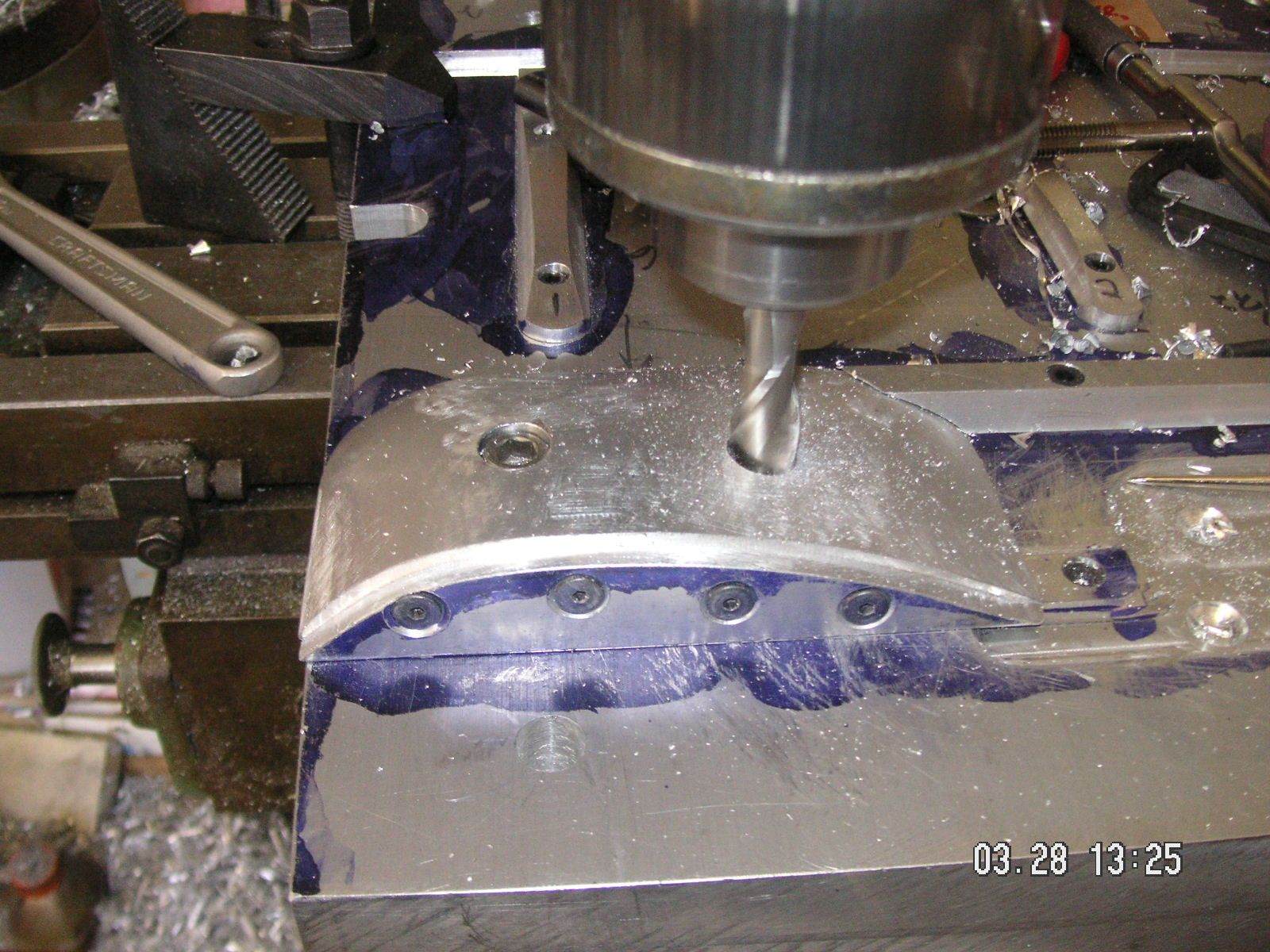
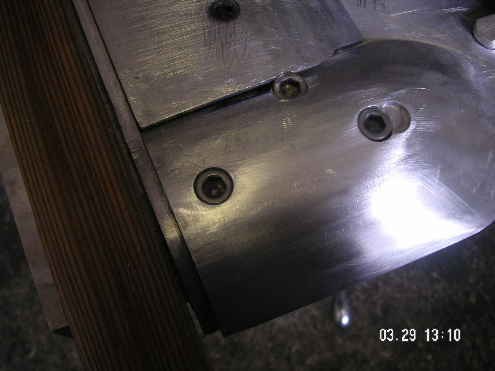
I first cut the additional three guide slots in the sides of the top plate then repositioned the plate and mounted the larger of the bulge forms, the two part one for the vent tube and alternator. Now before I move the top plate I'll drill the little set screw holes in threee of the rib ends and then I can move the plate to the other end of the mill table and drill the other set screw holes, then mount the smaller bulge form.
You can see that I made two false starts with the mounting holes in the larger part of the bulge form because I forgot to consider where I had put the guide slots. Duh!
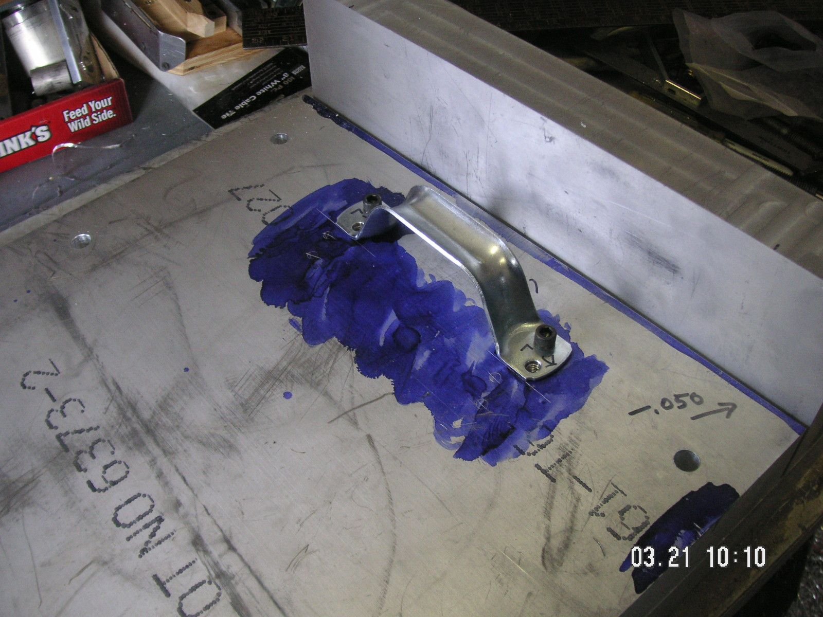
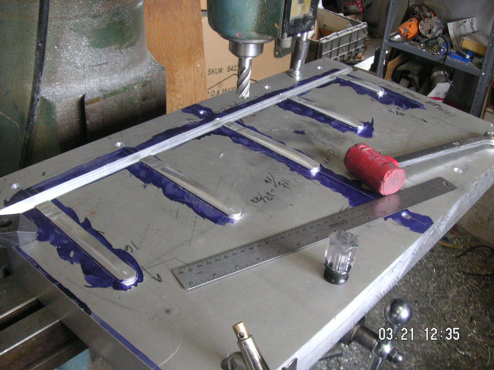
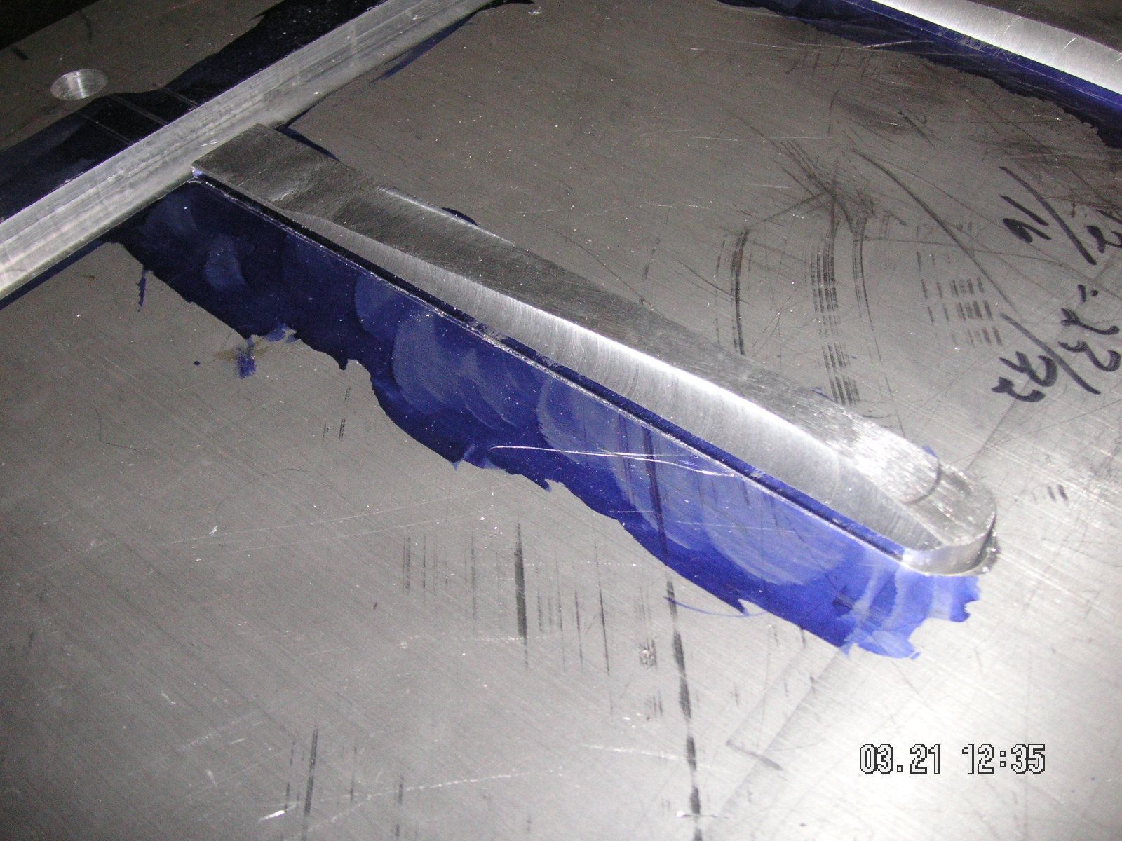
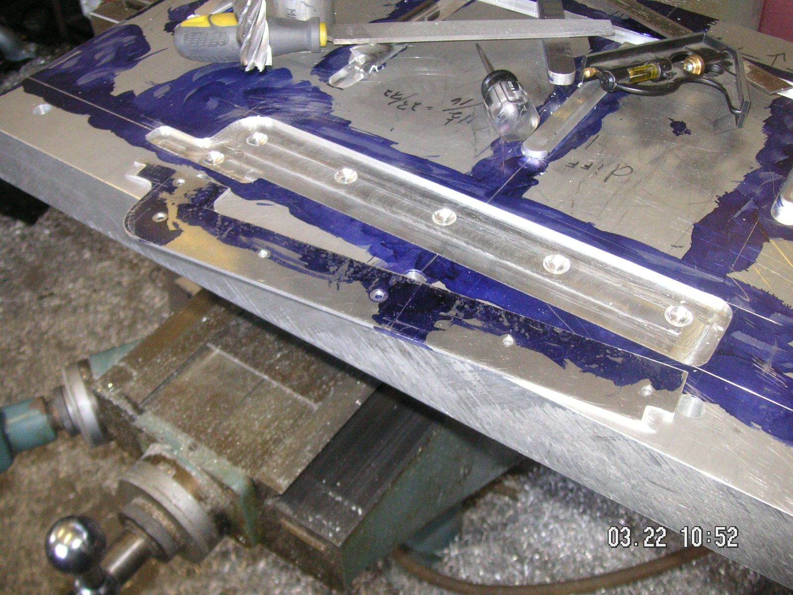
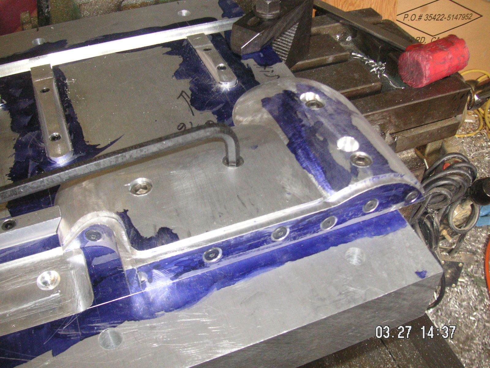
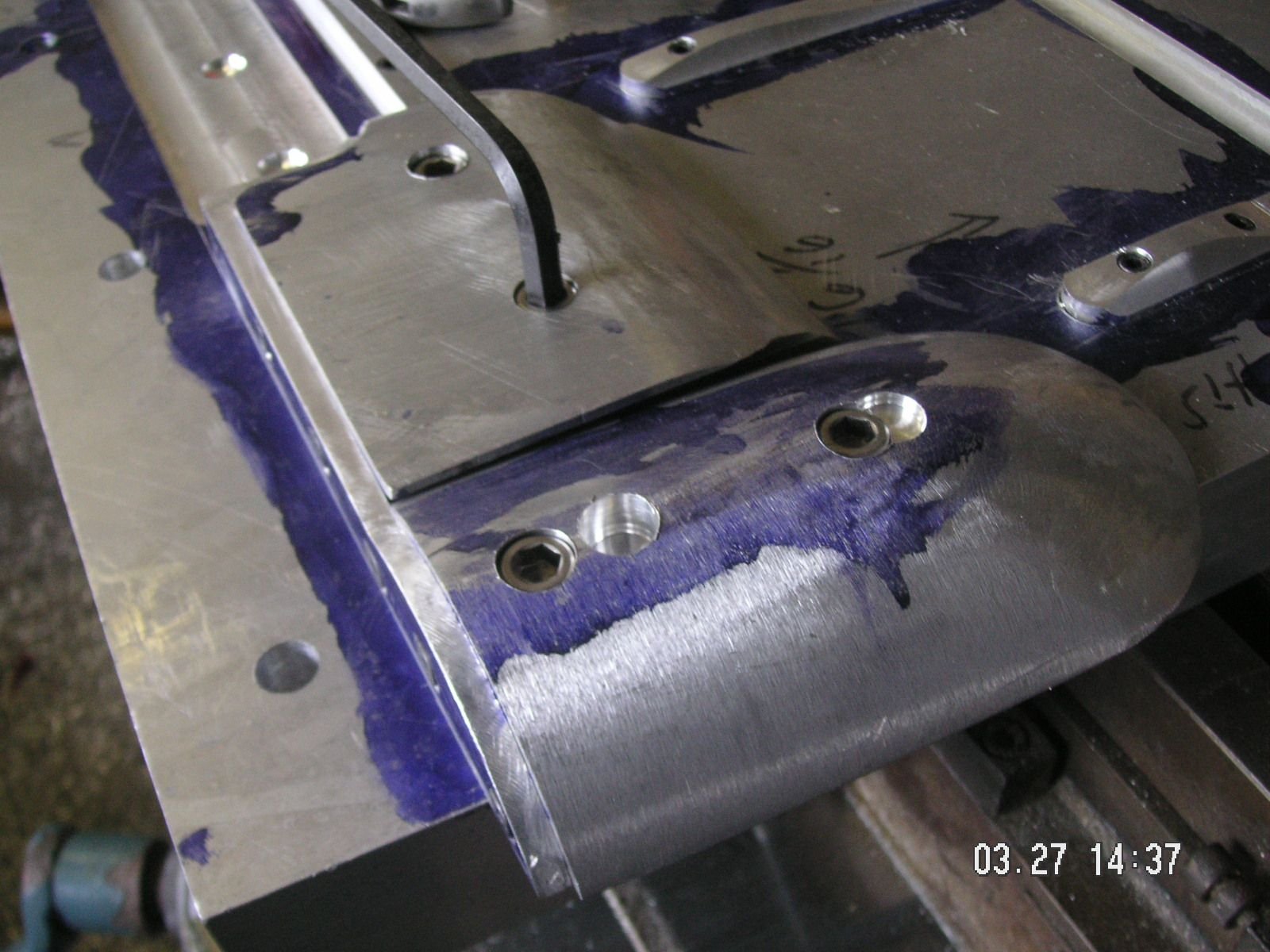
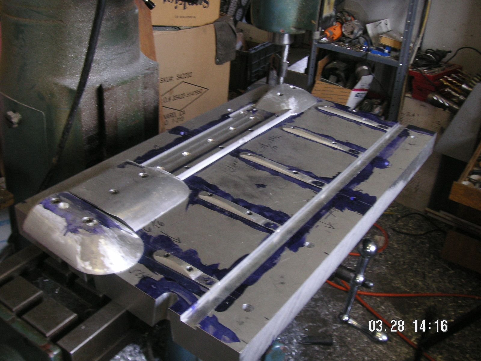
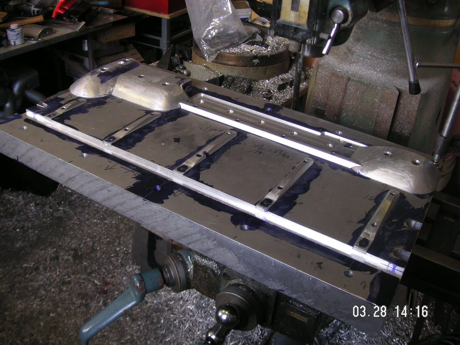
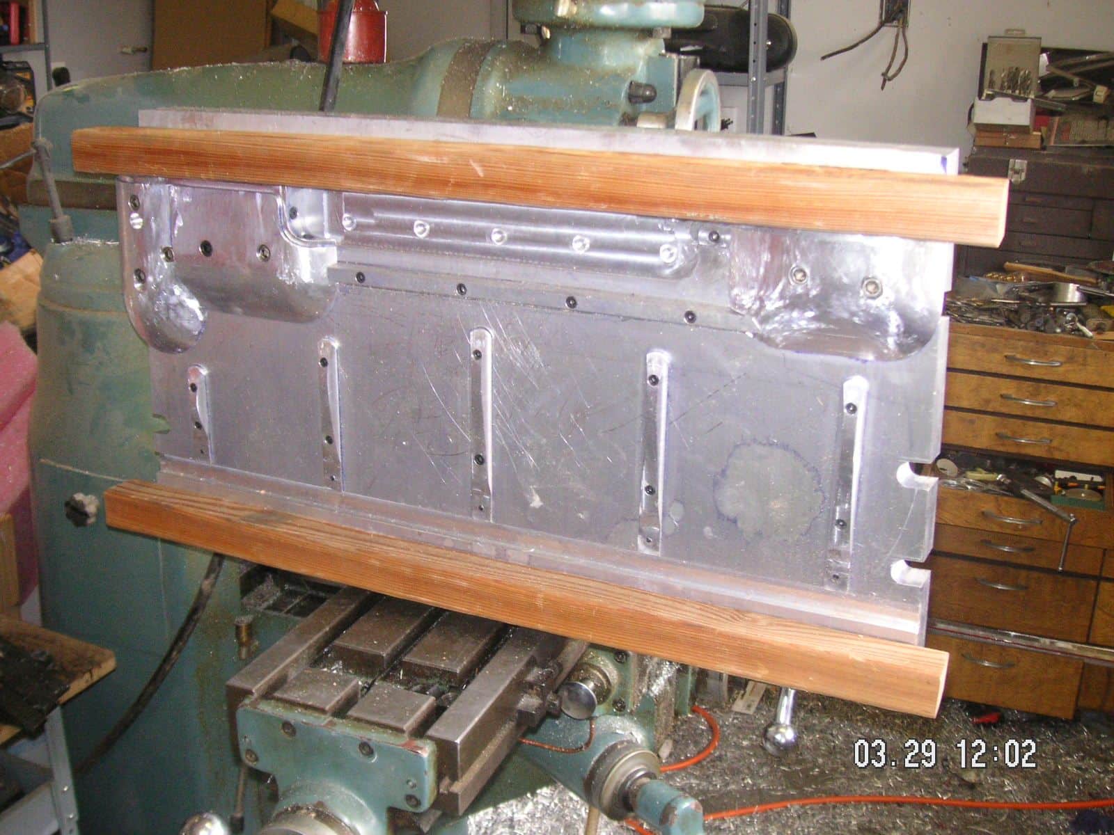
Well, I made a mile stone today. The top plate is essentially finished. That is, except for some refinement involving softening and polishing some or all of the forming edges so they will be less likely to shear the metal rather then forming it. Today I first drilled and tapped the holes to put the set screws in to mark the mounting holes. Then I located the final position for the smaller bulge form and firmly mounted it with two 3/8 inch socket head bolts. Here are some pictures including the completed form plate first with the marking dye and then I have cleaned up the Dykem with some laquer thinner.
I know it doesn't look like that much, but you have been following along and know what a chore it has been so far. Next I'm going to test this to see first if it will fit flat onto the bottom plate. That will mean I have the form pieces correctly located and not too to tall so that there is no interference. Then I might test to see if it will move about a 16th of an inch in every direction. That will probably not happen until I do the edge refinement, to both the the top and to the bottom plate. I also think there might be a bit of interference with the rib forms since I have a hunch that the recesses for them are not quite deep enough or that the forms themselves might be bit too tall. If so I'm not sure which way I'll correct them.
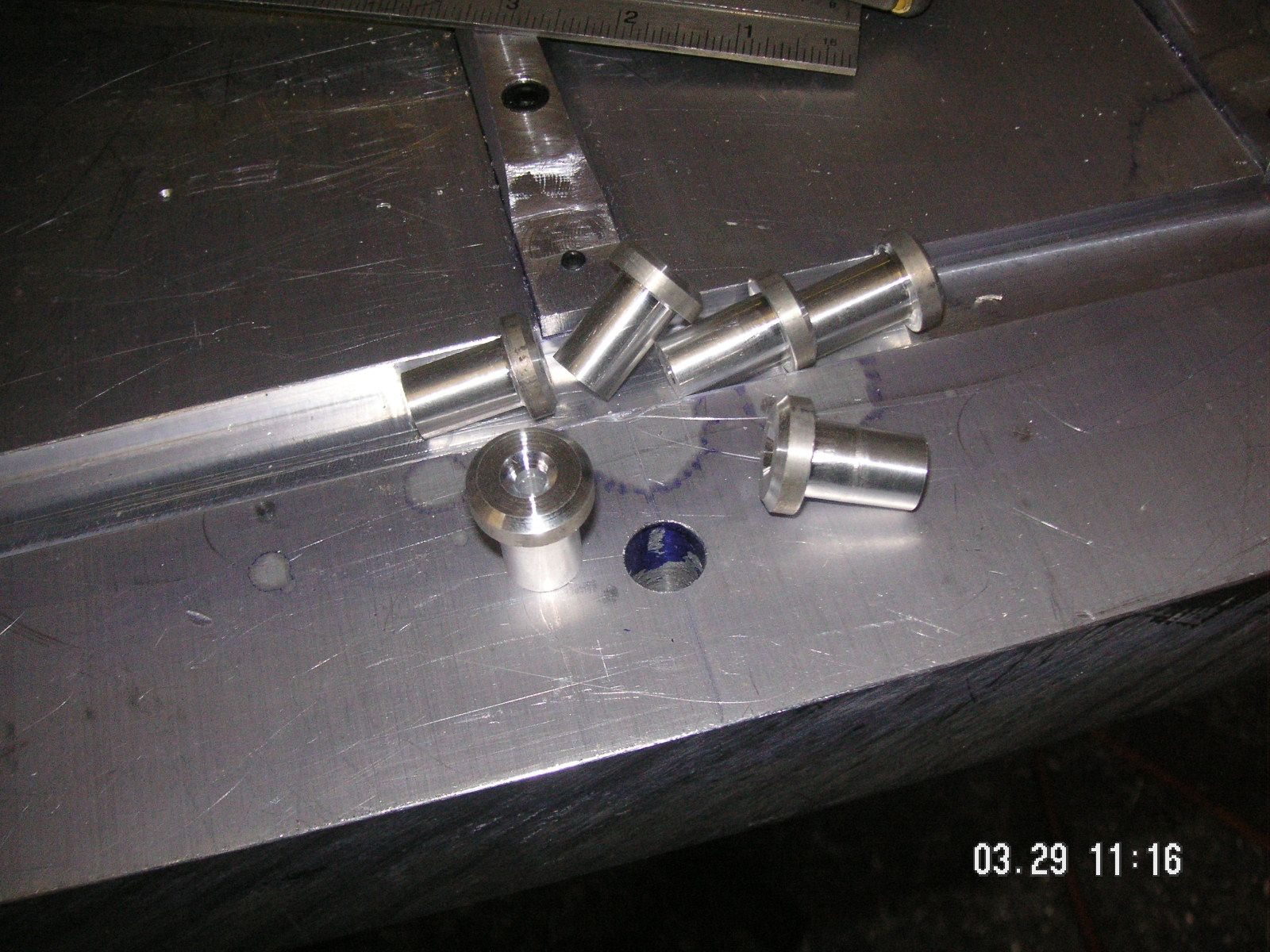
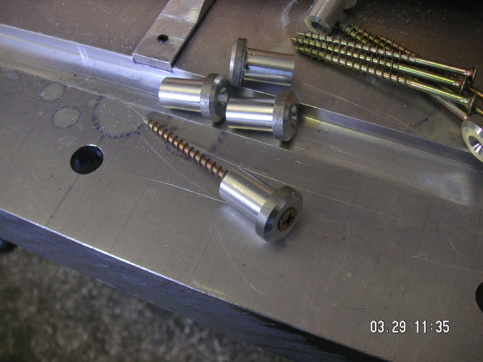
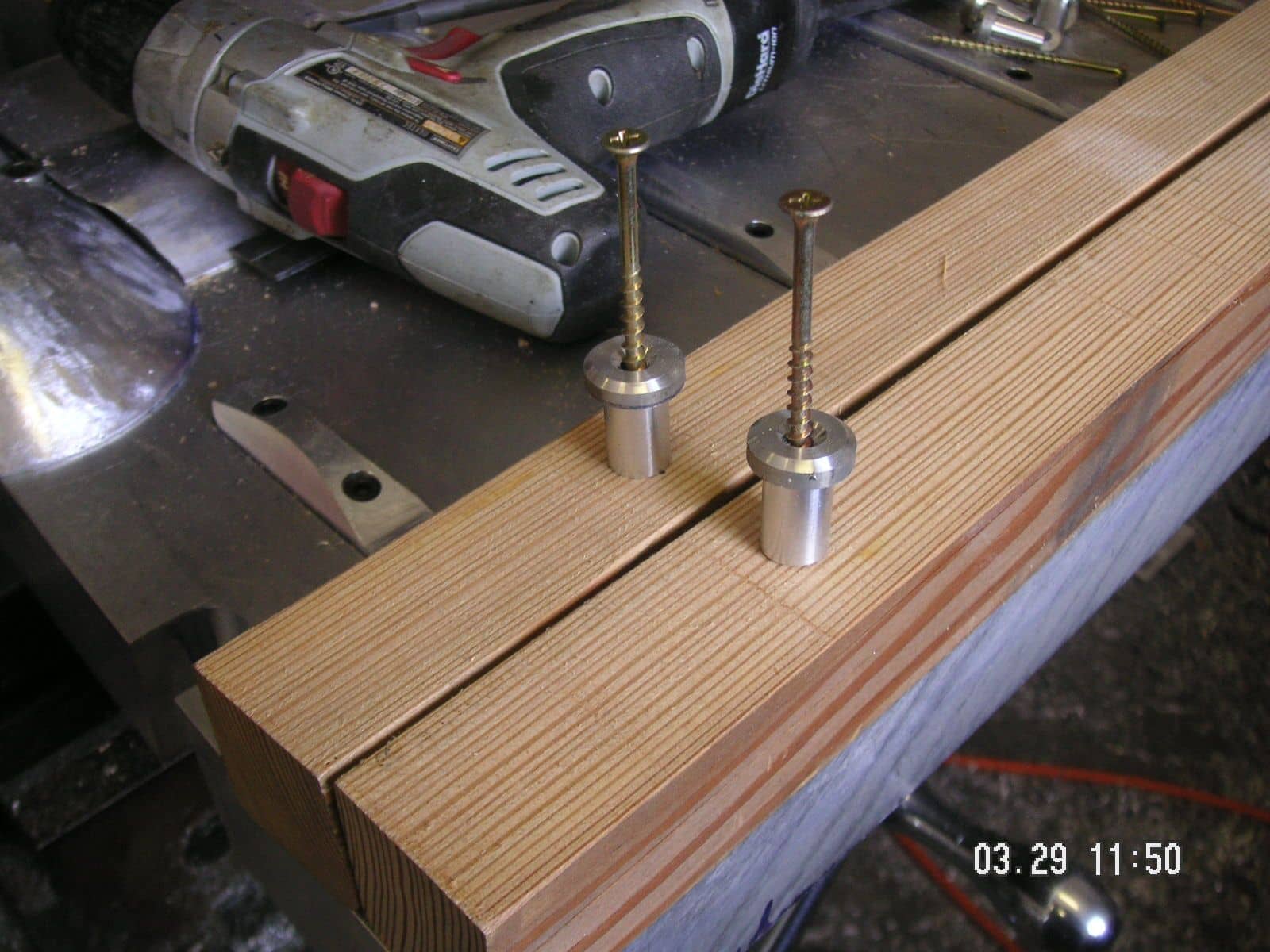
I got a little done today, so far. First I had decided that with all the handling that I expect will be needed with at least the top plate, and with the form items pretty much sticking out from the surface and over at least one edge, that I needed to devise some kind of protection for it. So, I made what I call some T-plugs so that I can screw some kind of wood protection rails on the foming face through the already holes but with some long regular screws. That's what I did. I have the rails temporarily screwed on with two screws each although I have provided for three. Then I bolted the handles on, but left it on the mill table so I could do some detail finish work on the forming edges and surfaces.
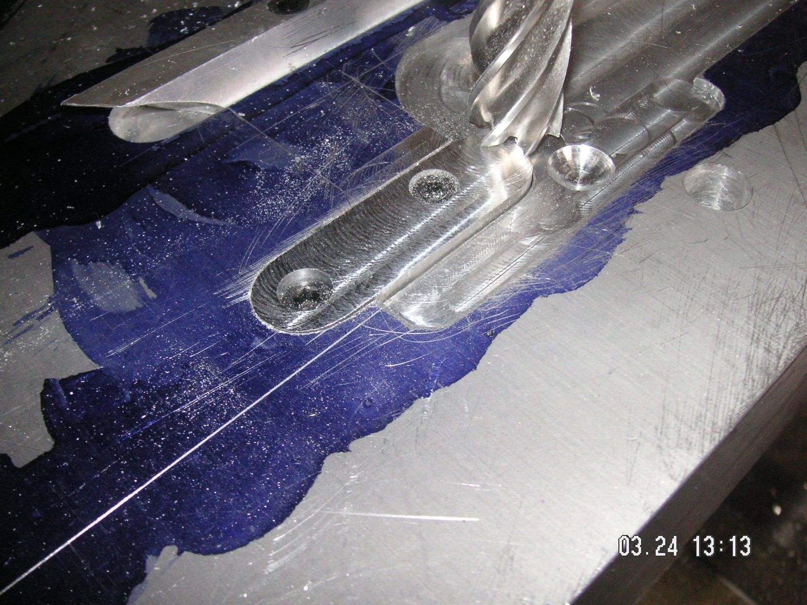
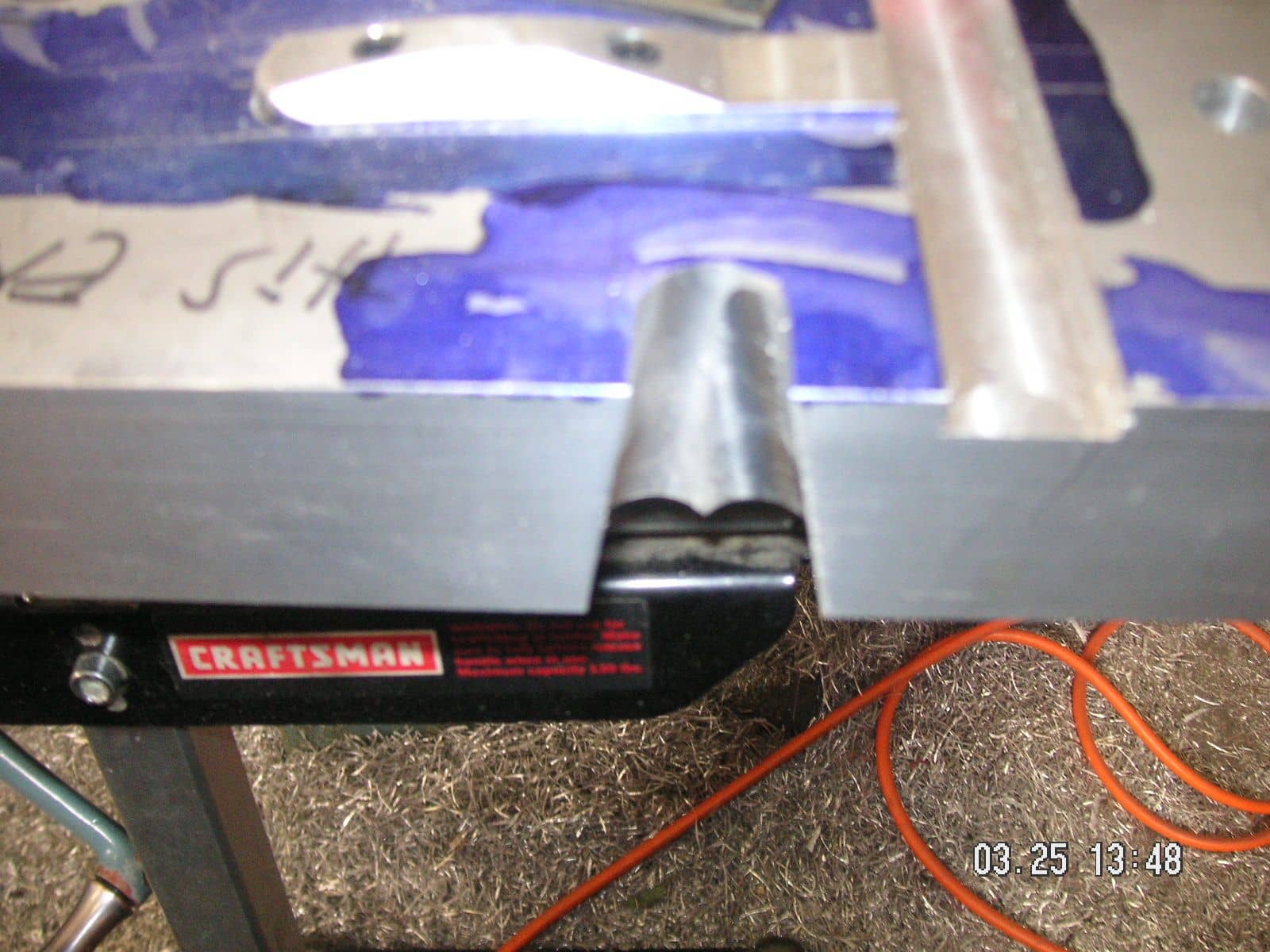
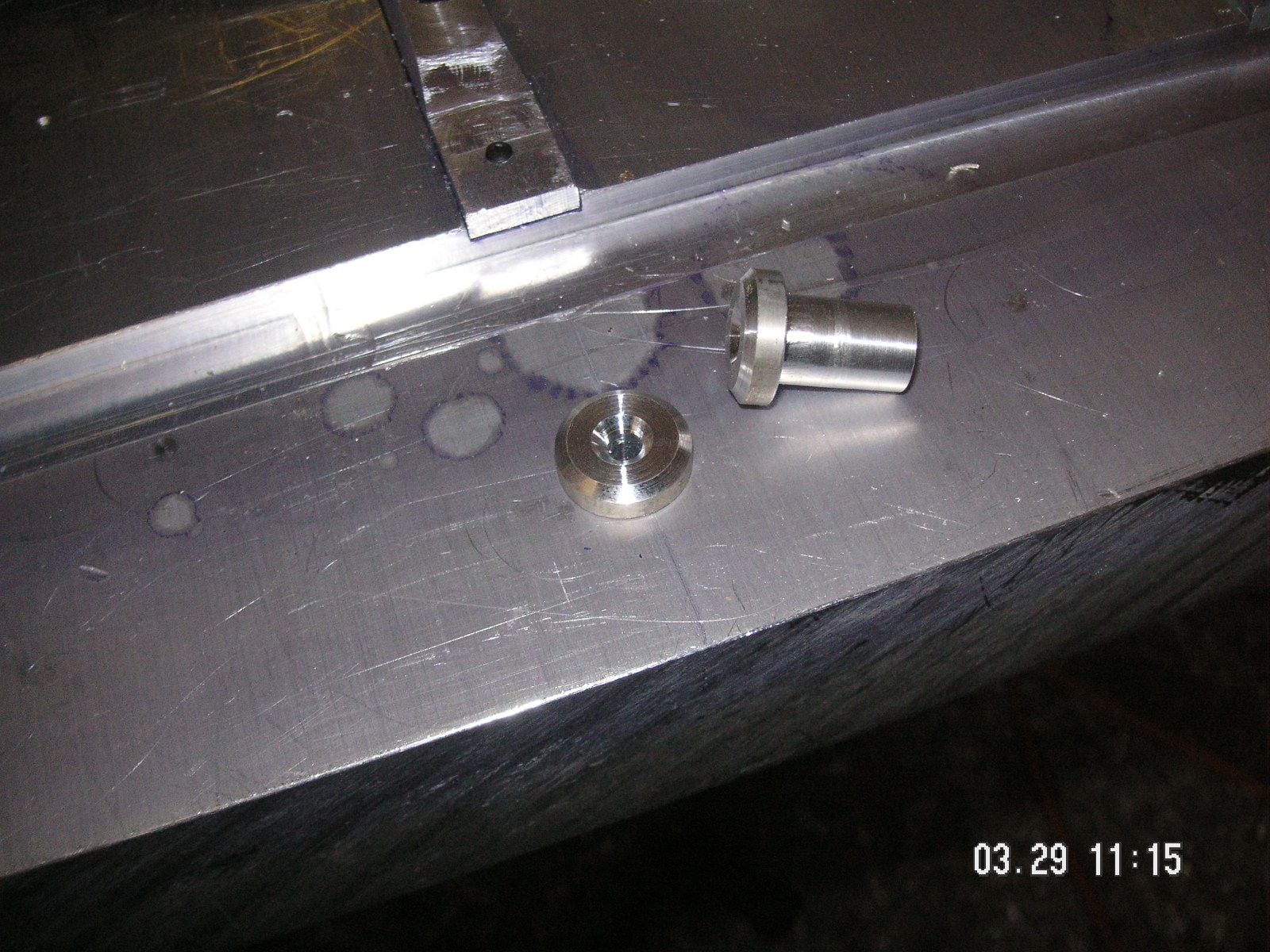
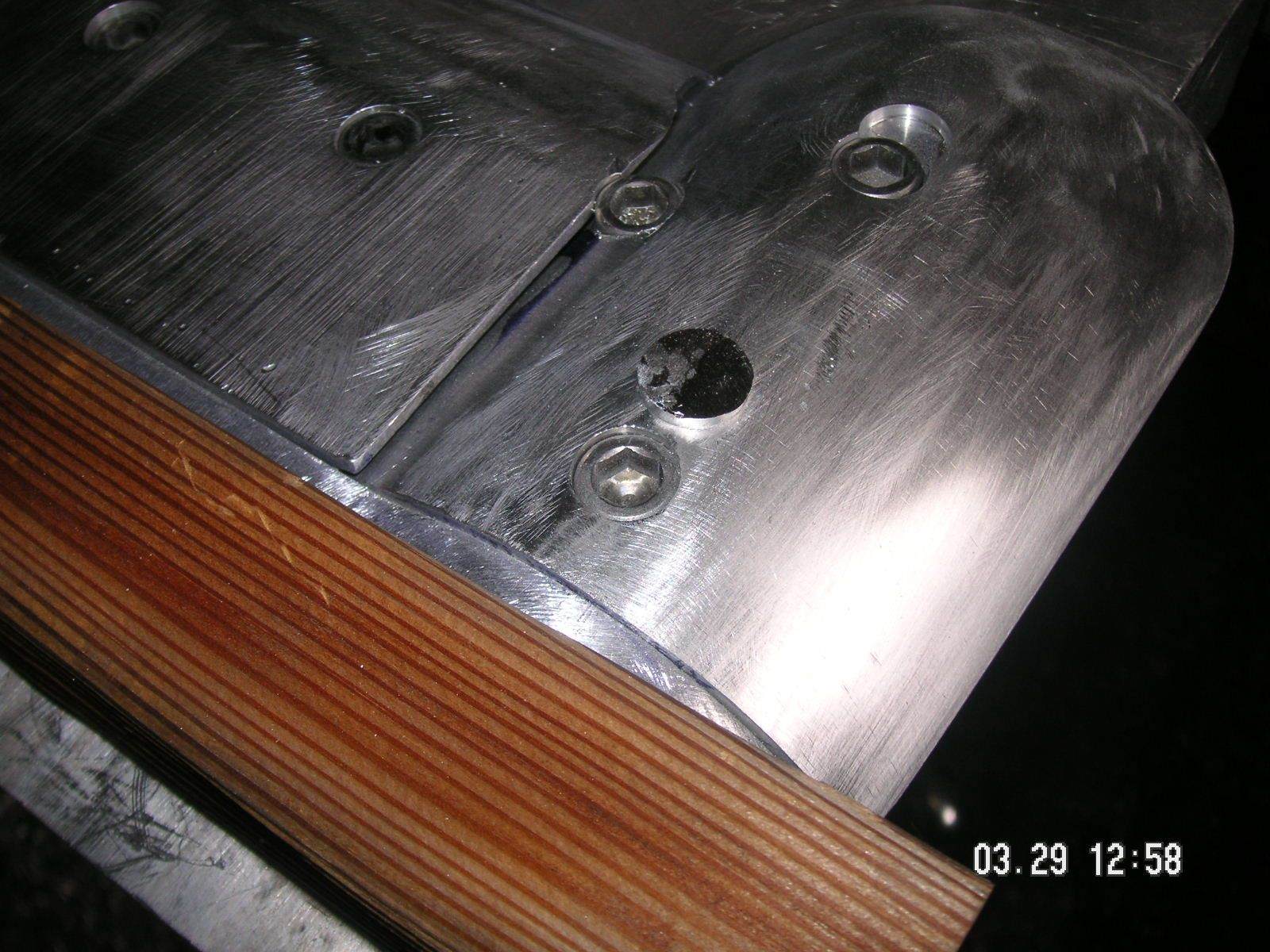
Then I decided that I ought to repair the mistaken counter bore that I had put in one of the bulge forms. So I turned a small plug out of some aluminum bar and turned it to a tight fit with a bit of taper. Then I cut it off and first hammered it into the hole then peened it into place. (I'll bet you have not hear or seen that work for a while.) (Too, I'll bet that you didn't know that that is what the small round head is for on a ball peen hammer.) Then I rasped and filed the top of it down flush with the bulge form surface. Now you can't even see it.
Now I have decided that I am probably going to need the guide slot that I put in at the wrong angle on the side of the top plate, so I am going to strip the form pieces off the top plate and bolt it to the mill table again, but upside down, and put in a patch so the the slot will be functional as a guide rather than just as a form for the corner brace.
One other thing I did was to put a third mounting bolt into the larger part of the large bulge form combo. I think that with the edge of that form kind of cantilevered out from under the top plate it might have a tendency to want to "rock' a bit, so I put the extra bolt opposite where the unsupported edge is.


 03-18-2020 | 07:25 PM