When you click on links to various merchants on this site and make a purchase, this can result in this site earning a commission. Affiliate programs and affiliations include, but are not limited to, the eBay Partner Network.
At Frenzy I asked Roger and Sean amid a crowd: “What parts are beginning to fail frequently?” Almost in unison they said “LH’s”.
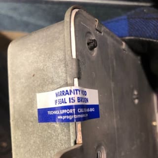
Not saying my LH is good, however the PO replaced it with a refurbished unit in 2007 or 18,000 miles ago. The refurbished LH was purchased from a vendor called ProgRama. I am not sure what they do or how they address the Hybrid board. Looks like they still offer a refurbished LH. If anyone has info on this vendor, please share.
LH and MAF Swap - Maybe: Based on some list members advice, I spoke to Louis Ott today and he was kind enough to lend me a LH and MAF to swap out to see if either resolved the problem. I just need to make the 50 mile drive to see him. I may drive out there tomorrow but we here in the PNW are bracing for some serious weather of rain/ice/snow so I am not sure I will be able to get out there since driving through The Gorge can be dicey in bad weather.
WSM MAF tests: I realized i did not have my multimeter connected correctly when I bench tested the MAF (see above post), after I figured that out I tested the Hot Wire circuit in the MAF and saw the proper resistance. Inspired, I decided to run through the rest of the MAF tests outlined in the WSM. I wasn't able to test the live burn-off test since that would have required running the car until warm, but all the other tests passed:
a. Power supply: Battery voltage: 12.4v
b. Hot Wire resistance: 4.1 Ohm
c. Hot wire signal: 1.74v (blowing on MAF causes voltage to increase to 5v.
d, hot wire burn-off: Not Tested.
This is looking fairly promising. I want to finish the final test before swapping out the MAF.
MAF Harness Continuity tests: Since some were thinking the sporadic nature was indicative of a short, I also tested each of the wires for continuity back to their origins and gave the harness a good wiggle at the connector to the LH and all wires passed. So I feel I can rule his hypothesis out.
Vacuum Leak Tests: I think I found my vacuum leak and potentially the source of my problem .The vacuum line feeding the fuel dampers popped off the port on the top of the plenum.
I haven't, fixed it yet. But this would make sense to me if the fuel dampers lost pressure the the motor would die. The fact that the problem started and progressively got worse over the course of a couple minutes tells me that it wasn't seated properly and worked off some how, maybe the torquing of the motor worked it off, meaning i had it routed incorrectly. Thoughts on my theory?
Now the real trick will be to try and reinstall it without removing the manifold!
Last edited by Michael Benno; 02-09-2019 at 03:21 AM.
Losing vacuum to the dampers and FPR causes the mixture to go rich with higher pressure. manifold pressure changes affect only the FPR; dampers use the vacuum connection to safely sweep up any fuel that makes it past a damaged diaphragm.
I suspect the disconnect of that vacuum line will cause little to no effect due to ingress of false air but it will likely cause a significant fuelling issue. The fuel injection mapping is calibrated against a fixed differential pressure between the fuel rail and the inlet tract. It is not practical to take the sensing point from the point of injection so it is taken inboard of the throttle plate and that is accurate enough. When the throttle is fully open most of the pressure drop is taken between the plenum and the runners/valves and a little pressure drop occurs across the inlet tract between the nose cone and the plenum. Thus when the throttle is fully open atmospheric pressure and the pressure at the sensing point are not vastly different and the impact should be some small amount of further enrichment of the mix. When running at idle the engine will pull a deeper vacuum but, as the fuel pressure regulator thinks the manifold pressure is atmospheric and responds to such, the fuel flow will be greater than calibrated because the differential pressure is greater than the brains think it is. Thus at idle you should be running quite rich and at full throttle you will be a bit richer than normal. Thus take a look at one of your spark plugs to see if they look "sooty"as I suspect they may well be. I have never tried running my motor in this condition but I am somewhat dubious as to whether it would explain the symptoms you describe. I think it should be possible to get the vacuum connector back on to the nipple as is but it may be a bit tricky - or so I suspect.
Whether or not this fault is the cause of your running issue remains to be seen however be careful here- there are two vacuum line connectors within the throttle body- one is upstream of the throttle plate [i.e. MAF side] and the other is downstream of the throttle plate- the connection downstream is the one the multi way vacuum connector has to be attached to. Note; the upstream connector is used to open the tank vent valve adjacent to the expansion tank.
Vacuum leak repaired, manifold holds 3spi now per WSM. I put everything back together to finish the final MAF test. But now car won't start, just cranks. I jumped the FP and I could hear it running. I am getting this sinking feeling of LH failure, funny how I got to experience it in real time. The plan is to swap the LH out with a known good one one the snowmageddon abates.
Thanks @dr bob and @FredR for your continued support as I learn my through this.
One of those situations where I wish I could say I was wrong. It is sounding rather ominously like LH failure but until the culprit is pin pointed do not rule out anything. After doing something significant like removing the inlet manifold the old adage "start with what you last played around with" is a pretty safe basis for analysis but it is not guaranteed to find the culprit. LH failure when it happens invariably does so without warning- this happened on my late 90S4- one day it was fine the following day it hesitated to start and the day after it would not start at all. We fitted a known working LH and the problem was immediately solved. This will probably happen to you once you stop playing "Build a snowman".
At least with Louie round the corner as it were you have options- please pass on my kindest regards and best wishes when you meet with him- he was a great help to me during my formative years of 928 ownership along with a number of other prominent 928 personalities who most generously took pity on me in my splendid isolation!
Hopefully your solution is just around the corner- not that you will likely be going anywhere far in the 928 during snowy conditions.
Go through the same no-start diagnostics you'd use if this was a fresh case, assuming nothing. Check for spark, check for fuel pressure, check for injectors firing. Double-check MAF plugs, temp sensor connections, ICV connections, etc. It's way too easy to accidentally disturb surrounding stuff when focused on on a particular task.
I managed to cause a cooling fan problem while changing transmission mounts. Good thing the cooling fan wiring doesn't run under the intake...
I swapped out the LH with a good one from Louis Ott, this is one of remanufactured units from John Speake. This had no effect on the NO START condition.
I tested for spark using a screwdriver near the block. I saw no spark during cranking. I tried several times and made sure my driver was a good conductor and the block location was properly grounded.
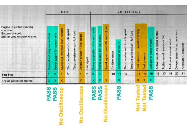
So based on Dr Bob's recommendation I started through the tests in the Porrche guide WKD 493 921: Test Plan for EZK-Ignition and LH-Jetronic '87. I followed the specific test procedures outlined in the guide.
I don't have an oscilloscope so I wasn't able to do all the tests according to the test guide. However, it seems as though I am honing in on a NO SPARK condition. As I understand the system, Spark originates from CPS sending an engine speed signal to the EZK and the EZK sending the Speed Pulse to the Ignition control units, as well as to the LH to trigger the fuel injectors.
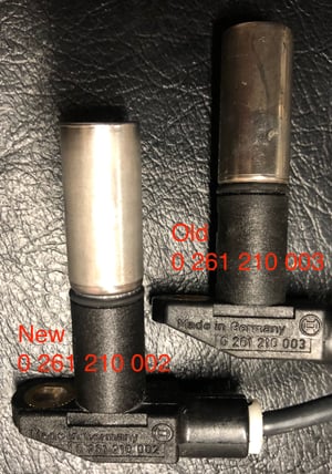
So starting with the CPS sensor, which was new. I pulled it and inspected it. It looks undamaged. The part number varies from the the one i removed. The difference being the length of the lead on the new unit is about 4" longer.
I was able to test connectivity of the harness for the CPS back to the EZK. All three leads are good. I am not sure what additional tests I can do without a scope. I saw a post with test for the CPS signal to observe the RMM's while cranking since the pulse signal is sent to the tach as well. When I crank I see an initial bounce of the needle but then zero despite continued cranking. Yet another datapoint for no engine speed pulse signal. As I read the manuals, spark starts with the CPS sensor sending signal to the EZK which in turns sends to:
Speed pulse to LH ECU Pin 1
Ignition pulse to control unit 1 (left)
Ignition pulse to control unit 2 (right)
I wonder if I can hook up my DMM to the LH connector Pin 1 and see the Speed pulse signal?
Your thoughts and ideas are appreciated. I am kinda stuck at this point.
Last edited by Michael Benno; 02-12-2019 at 09:56 AM.
Got your note and will talk to you tomorrow if the snow stays away in the morning.
In the meanwhile, stupid stuff. Lock the car door with the door closed and key from outside, then unlock it. Sometimes the alarm system gets confused when we are reattaching ground leads with doors open, closed, locked, unlocked, hatch, hood, then ignition key. Close everything. lock and unlock with the key, and the alarm should be out of the picture.
Lock the car door with the door closed and key from outside, then unlock it. Sometimes the alarm system gets confused when we are reattaching ground leads with doors open, closed, locked, unlocked, hatch, hood, then ignition key. Close everything. lock and unlock with the key, and the alarm should be out of the picture.
As I am aware [and that is not saying much when it comes to electronics given I am probably one step up from the moron category] a DMM is squat use when trying to diagnose such issues. Ironically I have just taken delivery of a Hantek P1008 laptop based scope to help diagnose such issues. Before committing I had a chat with Dr Bob about such utility and concluded that it should be OK for our type of needs but one should not expect to "send a man to the moon with it"! I have yet to power it up but your situation might just get me to pull my finger out and test it given I promised Dr Bob some feedback after taking his wise council as to the potential utility of such item! I purchased a set of test leads to support the item- whether or not I need more remains to be seen but somewhat ironically, the reason I wanted such was to be able to diagnose the very issue you are seemingly facing.
I take it from your note you have never had this CPS running so it may be a "dead in the box" scenario- correct? For some reason I have it my head that the unit you have is the 944 sender- does the same thing but needs a slightly longer cable on that model.
I take it from your note you have never had this CPS running so it may be a "dead in the box" scenario- correct? For some reason I have it my head that the unit you have is the 944 sender- does the same thing but needs a slightly longer cable on that model.
Fred, See posts 59 and 64 above. The car has been running driving fine since completing the intake refresh.
Yes, I’m using the 944 CPS sensor which I believe many folks have used with success.
Fred, See posts 59 and 64 above. The car has been running driving fine since completing the intake refresh.
Yes, I’m using the 944 CPS sensor which I believe many folks have used with success.
Michael,
You have managed to get the car up and running but have no mileage of any note on the CPS- correct? Not exactly a "dead in the box" scenario but possibly an initial burn in period type of failure.
Testing the Crank Position Sensor using a Digital Multimeter
If you’ve been reading along, I think I have traced my NO START condition to the Crank Position Sensor (CPS). The WSM referenced above recommends using an oscilloscope to test the CPS signal. However many of us don’t have oscilloscopes. The scope is the most precise way to determine how well your CPS is functioning, you match the observed wave pattern to the one in the WSM. However, there is some basic functional testing you can do with you with a digital multimeter (DMM) based on the google research that I have done.
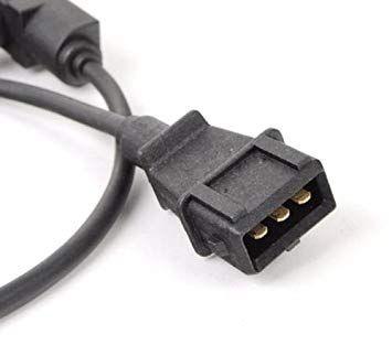
The BOSCH CPS sensor in our cars is a 3-PIN style and the pins correspond to the following
PIN 1 - 12v positive - supplied from the EZK
PIN 2 – 12v negative - grounded to the EZK
PIN 3 – Sensor Signal - WSM calls this the “Shield” this goes to the EZK
The way the sensor works is that it is powered with 12volts via PIN 1 and PIN 2. And then the signal voltage varies as a metal object passes within close proximity of the sensor head. So to test the sensor, you need to make sure powered circuit is good (resistance test) and that the signal is present and oscillates. In my research I found several examples of the same basic tests a bench test and in-car test. I am doing these tests on the bench since I had already pulled the sensor in my troubleshooting. I decided to compare my old sensor to my new sensor.
Bench Test 1: Resistance Across PIN 1 and PIN 2. Some resistance indicates the circuit is intact. Infinite resistance indicates the circuit is broken, No resistance indicates the circuit is shorted.
Observed:
Observed: OLD: 0.982 Ohms / NEW: 0.982 Ohms
Bench Test 2: Observe Signal Voltage when sensor is powered
- Connect sensor PIN 1 to the positive lead of the charger
- Connect sensor PIN 2 to the negative lead of the charger .
- Connect sensor PIN 3 to positive lead of DMM
- Connect negative lead of DMM to negative lead of the charger
- Set DMM to AC volts.
Observed: OLD: 2.98 volts AC / NEW: 2.31 volts AC
Bench Test 3: Observe Signal Voltage when sensor is powered and passing steel object in front of sensor head.
- Same setup as above
- Pass steel object across sensor head repeatedly
OLD: 2.98 volts AC <--oscillating to--> 1.45 volts AC
NEW: 2.31 volts AV (no oscillation)
So based on this, what do you guys think BAD CPS sensor?
I have another NEW sensor arriving tonight so I can test a third datapoint.
Last edited by Michael Benno; 02-14-2019 at 03:36 PM.


 02-09-2019, 02:44 AM