When you click on links to various merchants on this site and make a purchase, this can result in this site earning a commission. Affiliate programs and affiliations include, but are not limited to, the eBay Partner Network.
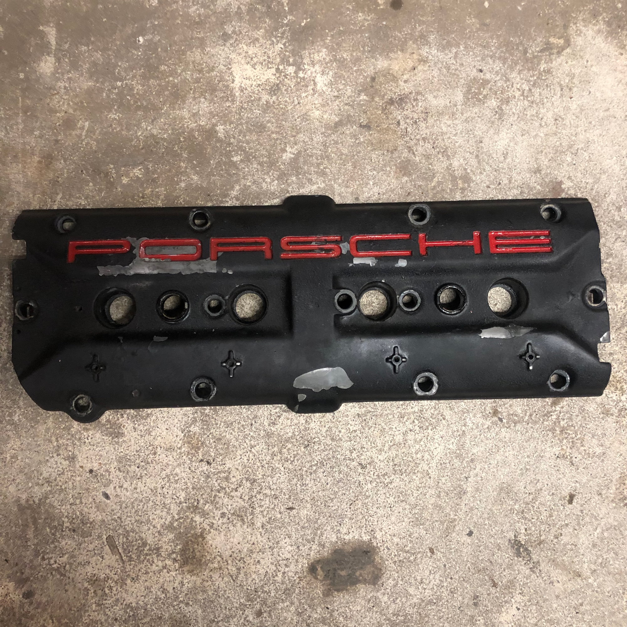
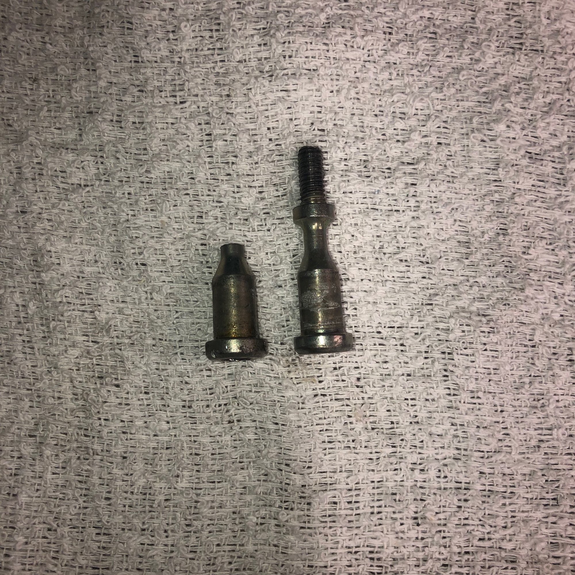
I decided to remove the intake covers. Well, I am halfway.... And like most projects I ran into a few snags. I snapped one of the valve cover bolts on removal but thankfully I was able to put my new stripped bolt extractors to good use and was able to extract the bolt. Are these valve cover bolts prone to breaking? Are there a required replace item when changing the covers?
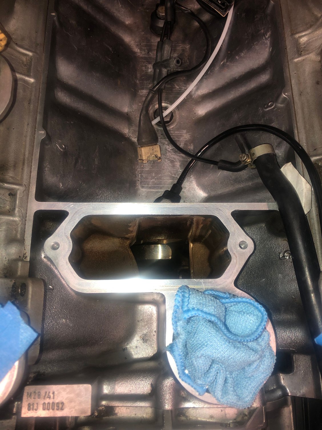
I'm a little stuck removing the passenger side cover. I have the bolts loose but cant lift it free. Do I need to remove the hall sensor?
No..should come right up. If you broke a bolt, was maybe over right and might be glued down too.
Personally I couldn’t see how to get that side off without taking the two hall sender bolts out and moving the top part of the sender out of the way. Mine is right hand drive so could be different.
No..should come right up. If you broke a bolt, was maybe over right and might be glued down too.
Jeff, the broken bold came from the driver side. I was able to get that cover off fairly easily.
Originally Posted by DuncanF
Personally I couldn’t see how to get that side off without taking the two hall sender bolts out and moving the top part of the sender out of the way. Mine is right hand drive so could be different.
The passenger side was quite difficult to remove. I had to remove both the bracket for the fuel injection harness at the rear of the head as well as the hall sender and still I had issues clearing the harness. The problem is the long plastic shroud on the rear valve cover vent prevents much angled lifting. It's best to remove all anchor bolts for the FI harness as well as those for the main fuel line.
FYI, I've read that accessing the Hall Sensor bolts is a real SOB. I found it pretty easy using a long extension socket driver once the air pump valve and engine hoist brackets are removed from the underside.
Regarding the Hall Sensor. My connector crumbled. Is it possible to buy a replacement connector housing? Looks to be the same connector used for CPS sensor and Knock sensors. I could buy a couple and rebuild the ones I pulled to keep as spares.
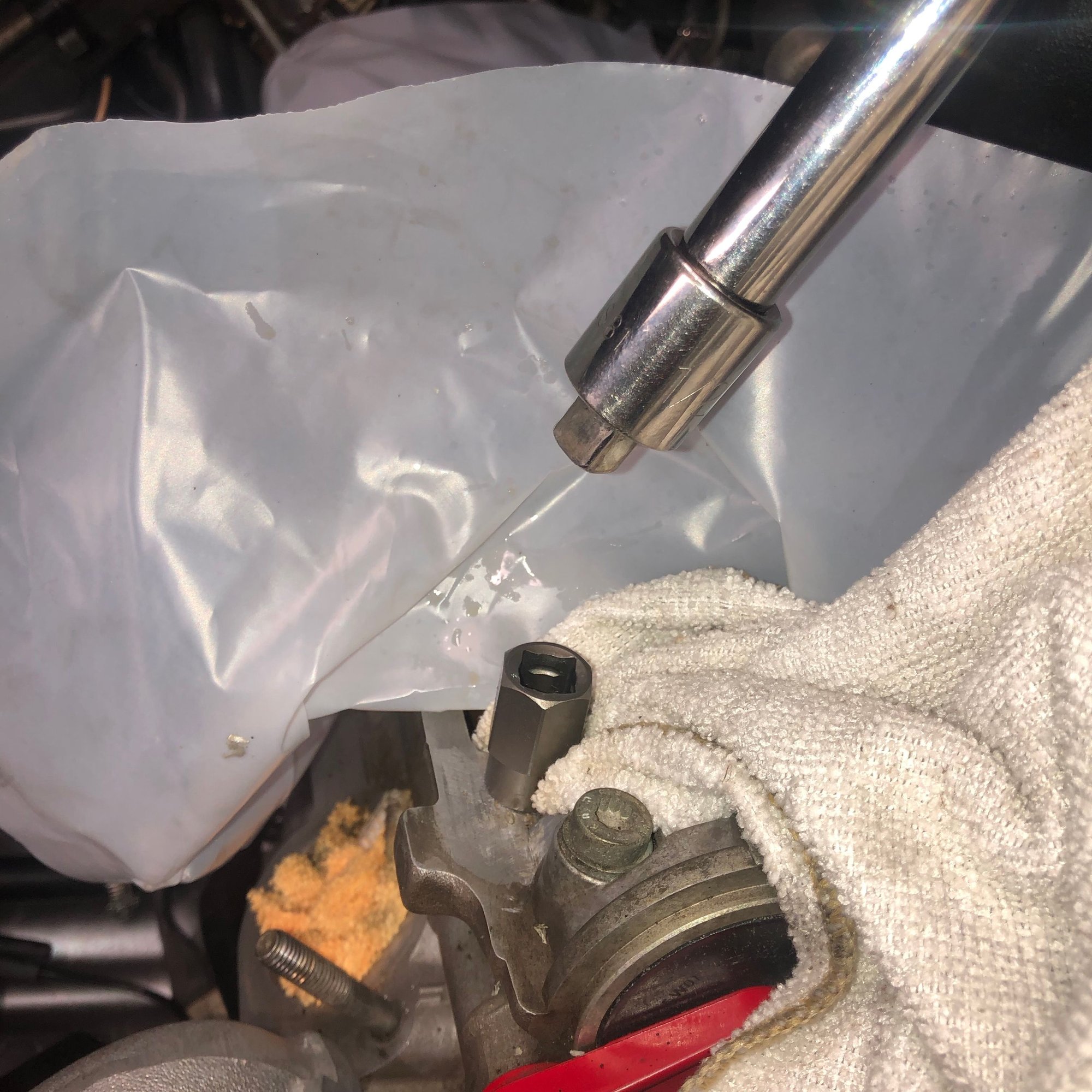
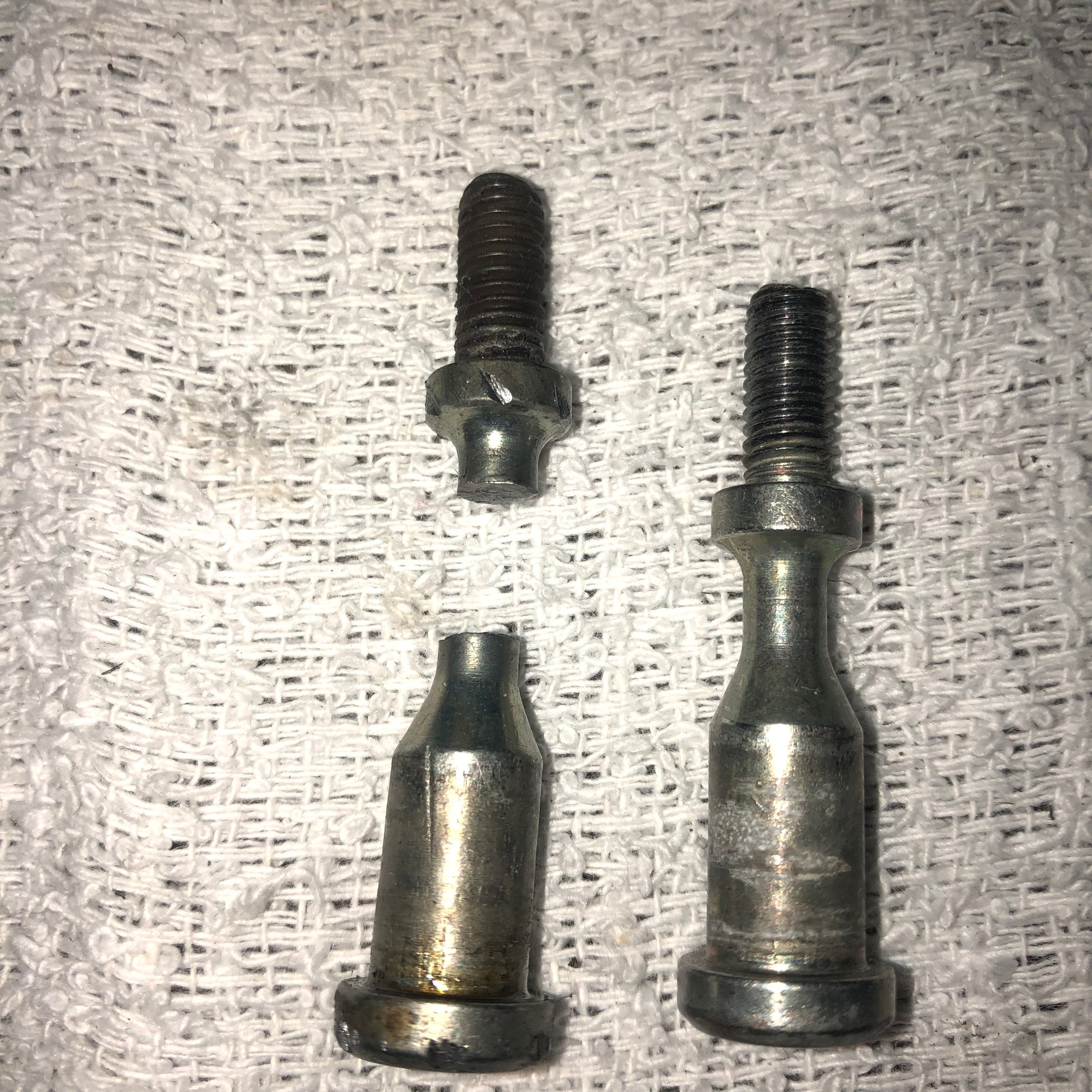
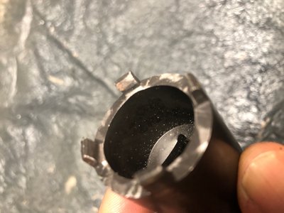
I can't remove these lock nuts they are both on too tight. I tried the PB blaster + hammer + screwdriver/punch, as well as long needle nose pliers and no luck. Is there a specific too used for this? Did someone make one from a 24mm socket perhaps?
I can't remove these lock nuts they are both on too tight. I tried the PB blaster + hammer + screwdriver/punch, as well as long needle nose pliers and no luck. Is there a specific too used for this? Did someone make one from a 24mm socket perhaps?
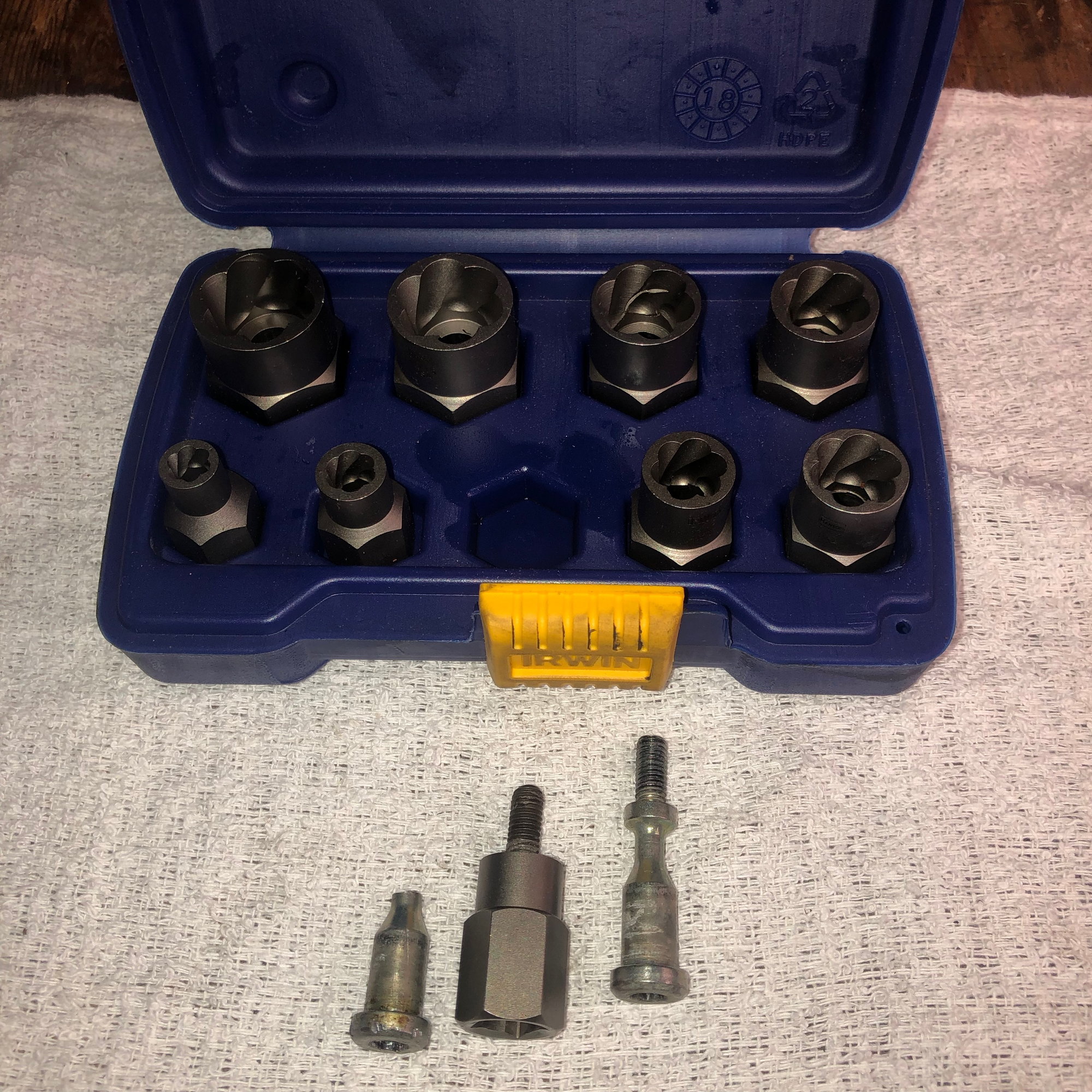
Cutting down a socket should work but I used one of these
@DuncanF, thanks for the good tip on the pinned socket. The notched nut on the valve cover measures 25.1mm at the narrowest point. The diameter of the pins on the socket drive measured 19mm/23mm but with some searching I was able to find a slightly larger
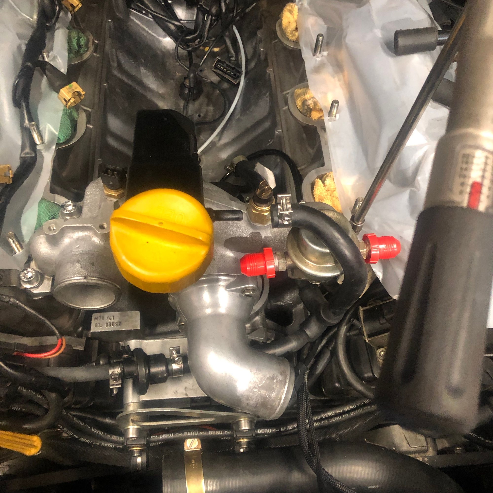
Oil filler neck and Hans baffle installation and proper sealing
There has be a good update to the process of installing the oil filler neck. There are variations for the metal vs plastic neck and whether or not one is using an aftermarket oil baffle. You can check that out here: Installed a Greg Brown Baffle Today
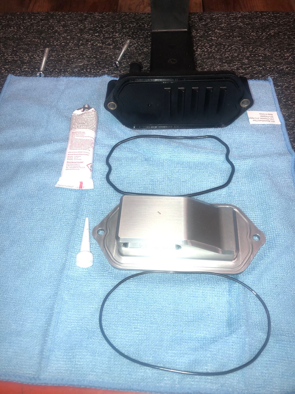
My car is a 1988 and has the plastic filler neck with an integrated baffle. The issue with these plastic units, is that they can warp over time creating an uneven seal. The tip on reinstallation is to use an appropriate silicone sealant in addition to a new seal. The recommended sealant is one that is heat and oil resistant. Consider Dreibond 1209, Hondabond 4, Yamabond, or equivalent from Permatex. I'll be using the Driebon 1209.
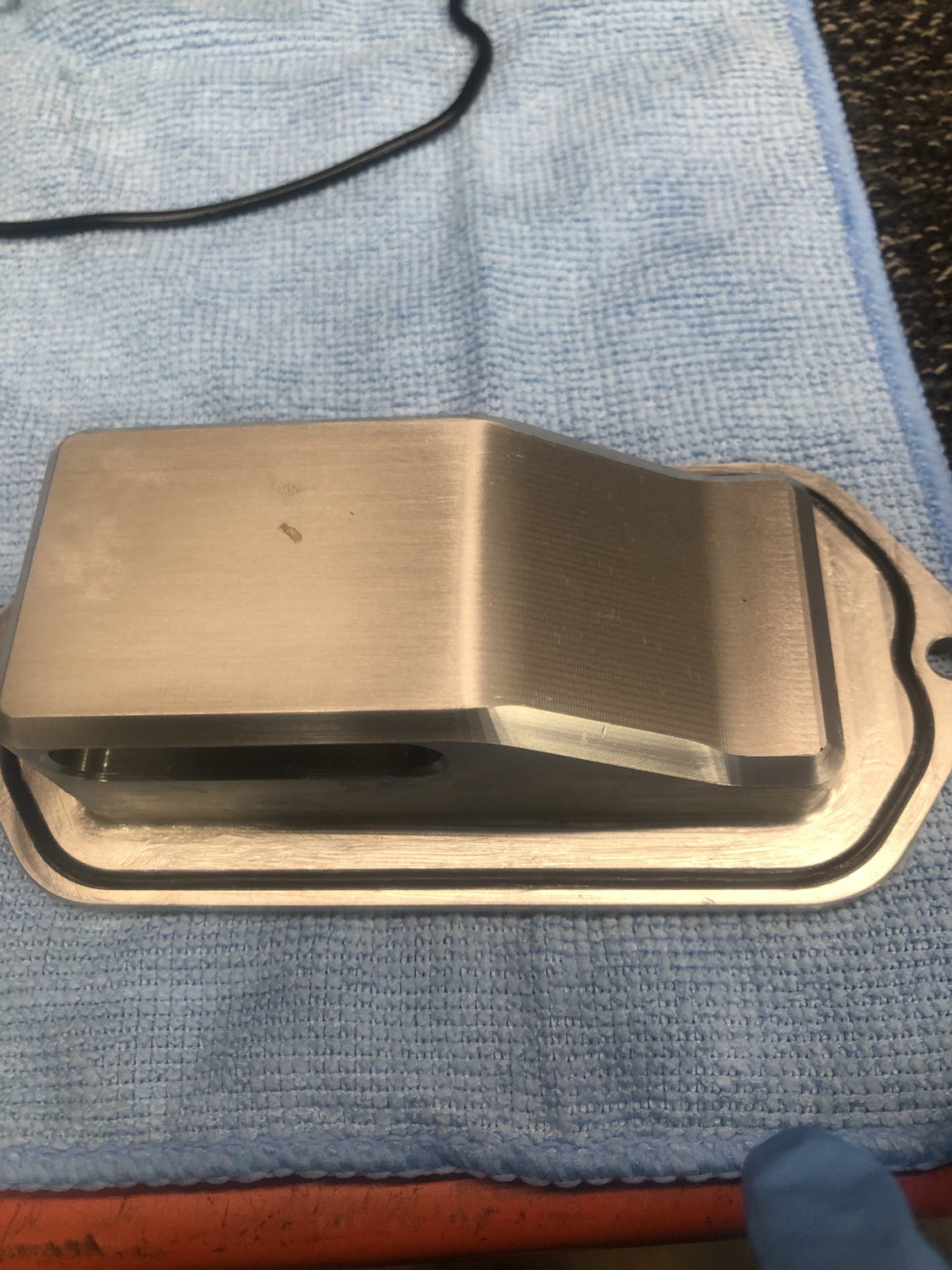
I will also be installing an aftermarket oil baffle by Hans. It's a little different than Precision Motorwerks and 928 Motorsports but I thought I would give it a try. This baffle has a groove for an O-ring similar to the filler next. Based on the linked thread above, the recommendation is add sealant to all the mating surfaces.
The sealant will set up in about 10minutes so its a good idea to lay everything out in advance. You can see the O-ring groove on the backside of the Hans baffle.
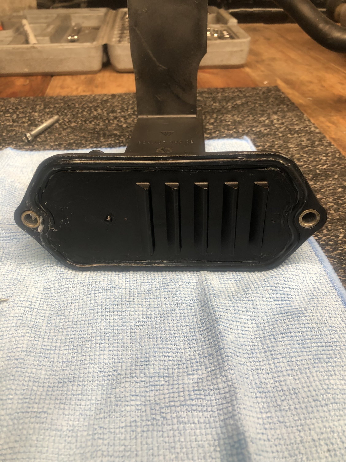
I put a bead of silicone in both O-ring grooves to help hold the O-rings in place. I also smeared a film of silicone on the flat mating surfaces.
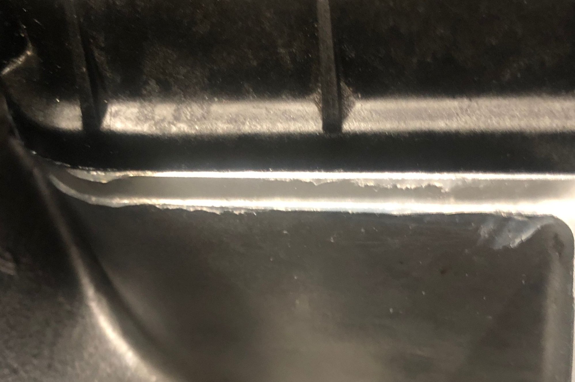
Once tightened down I could see just a little silicone pressing out the edges. Not too much.
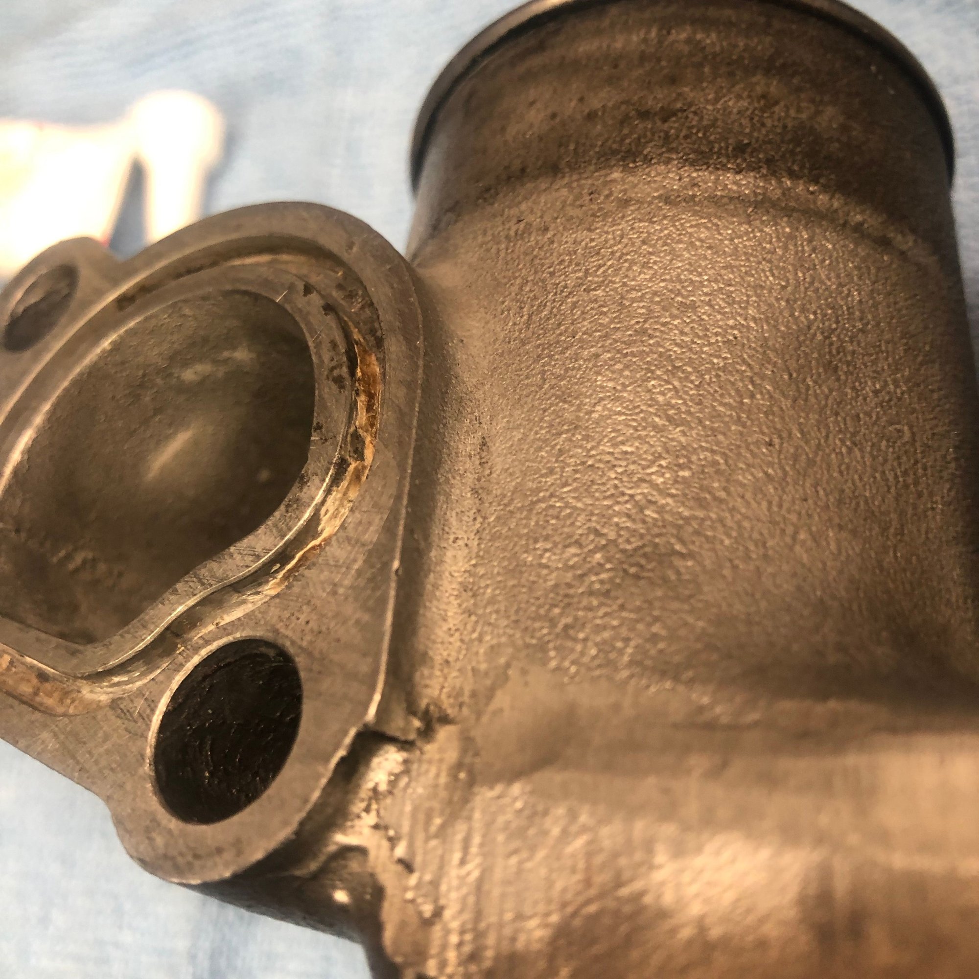
There was a really good recent discussion about proper sealing of the water bridge: Water Bridge red or-ring gaskets: Paper or Not?
As a result of that thread I decided to follow the recommendation and use an appropriate silicone sealant. In this case I used Driebond 1209 as it is a high temp sealant resistant to all sorts of stuff and I had some from my oil filler neck install. It seams getting a good seal is critical for this piece.
On inspecting the bridge, I noticed quite a bit of crud in the channel for the O-ring. I made sure all that was removed before installation.
I put a bead of silicone into the channel and smeared a layer on the flat mating surfaces of the heads and the bridge.
I also used a little synthetic lube on the large O-ring that presses into the block to aid installation. I used new bolts and followed the 2-stage torque instructions: Stage 1: 10NM, Stage 2: 20NM +2. I am not sure what the +2 means so these are tightened to 20nm.
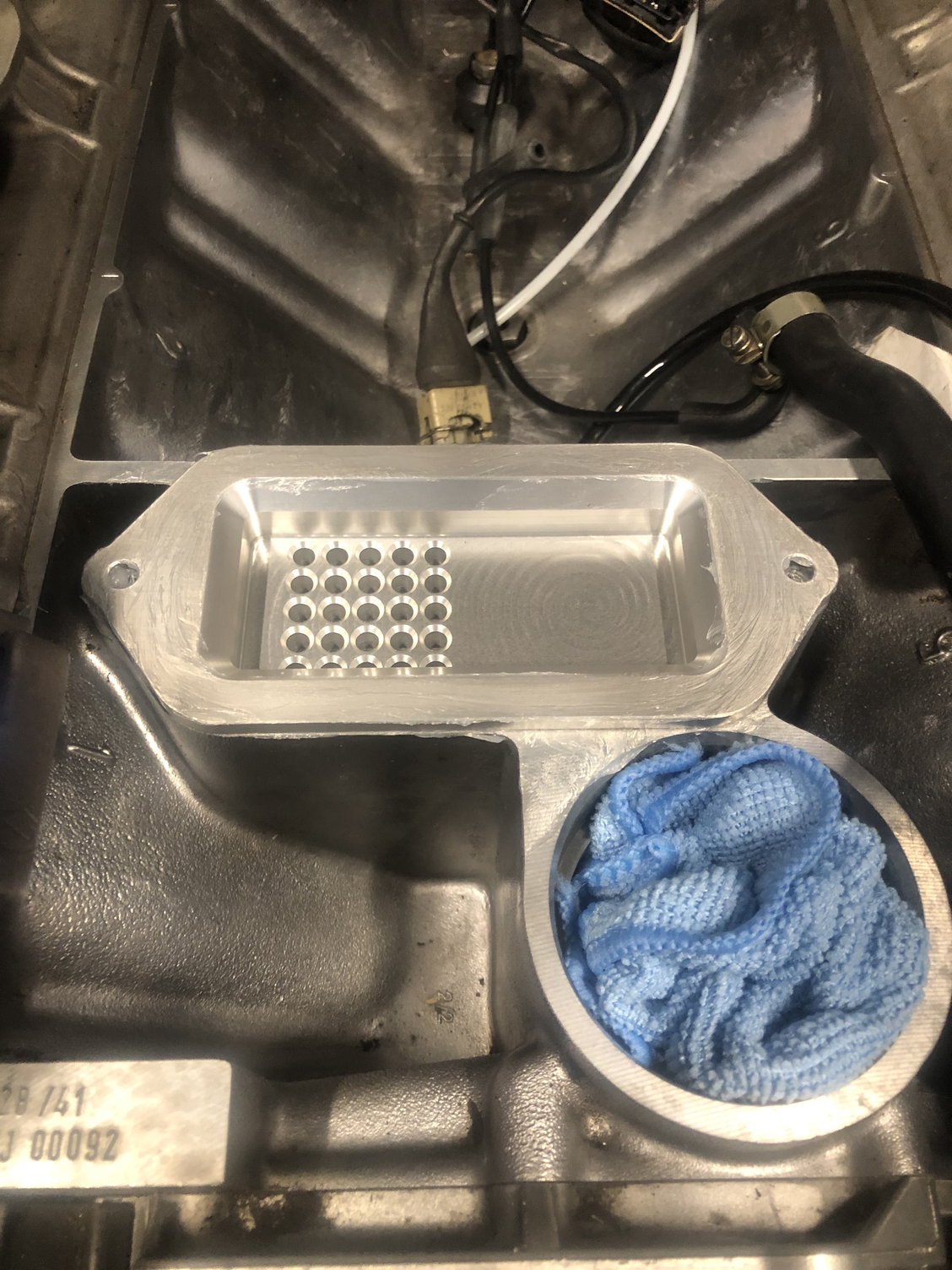
That oil baffle that Hans made is a work of art. The machine time to make it must be nuts.
I've looked at the design and I think it will be very effective.
I believe the "+2" means you turn the bolt another two flats (120°), but I hope someone who knows for sure chimes in.
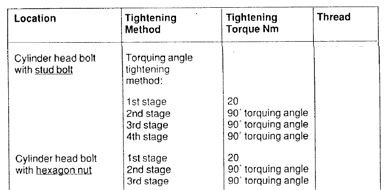
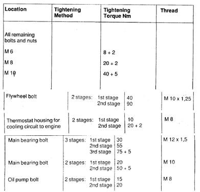
You know I could not get a clear answer on what the +2 means. I posted a question on this very issue in this post Water bridge bolts torque spec and didn't get a clear answer. However if you compare how Porsche calls out torque specifications, they specifically call out the +90° turns on the head studs
Here you can see the manual is specifically calling out the torque angle method with a starting torque.
Whereas, else where the manual commonly calls out this method of adding some amount +2 or +5. So Porsche is differentiating torque angle form adding more torque. So I have to assume +2 means adding 2 more NM. Although it would have been a lot more clear if they said 3 stages.
If anyone has a clear understanding of what the heck this means please chime in.
Bolting is generally designed to operate within a specified stress range. Thus if the spec reads 75+5 I would think it is advising you to ensure the torque lies within the range 75 to 80 NM.
When I had a problem getting my flex plate clamp to hold Porsche had no hesitation to recommend increasing the torque by 10% [it still did not work though]. I am not sure what the Porsche philosophy with regard to bolting stress is but bolts are commonly designed to be torqued to about 75% of yield and thus can easily withstand an additional 10%.
That's an interesting thought, Fred. You take it to be a tolerance spec of - 0 to +5. It may be.
What we have come to think it means is to bring them all to the spec (in this example 75 Nm) , then check them again by setting your torque wrench 5 Nm higher.
One thing that's for sure: It is confusing and I have never found an answer in a Porsche tech manual as to what they meant by that.
Then there's the discussion as to whether those torque numbers are dry, light oil, or what on the threads? Because of how much thread lubricants change torque, I always thought that they should call out what their torque specs are based upon.
Last edited by Carl Fausett; 01-07-2019 at 01:36 PM.

 12-24-2018, 12:40 AM