When you click on links to various merchants on this site and make a purchase, this can result in this site earning a commission. Affiliate programs and affiliations include, but are not limited to, the eBay Partner Network.
So as not to lose track of it, I cleaned and reassembled the lower cover and separator plate, then put them in a thick plastic bag for safe keeping. They will go back on after the rest of the shenanigans are done in the transmission.
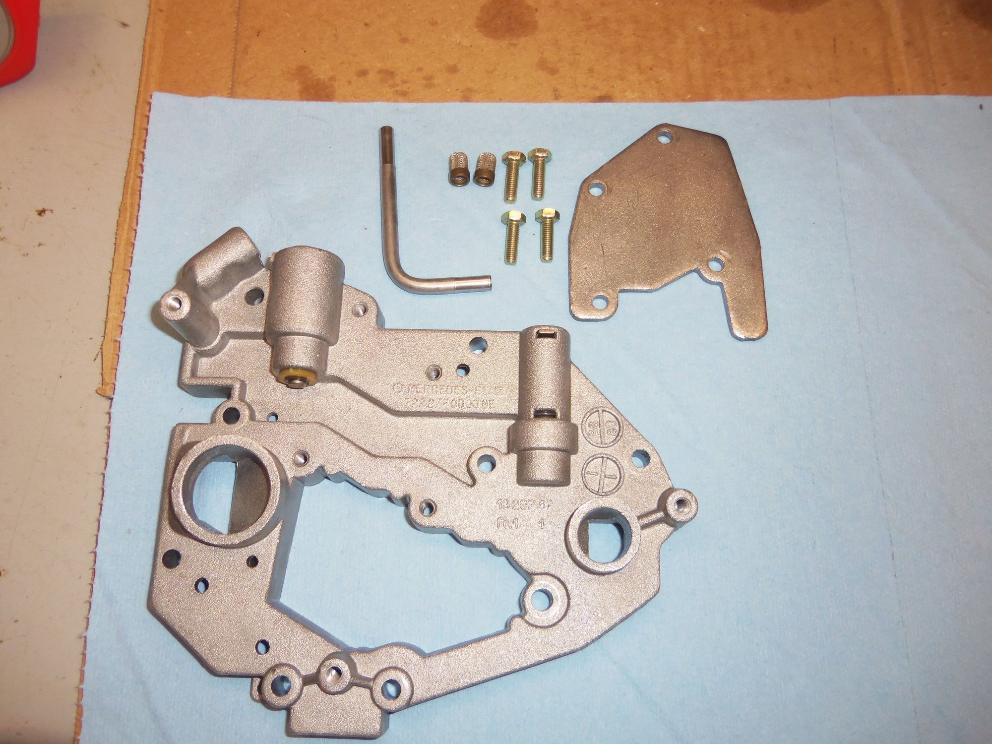
Lower cover and hardware, cleaned.
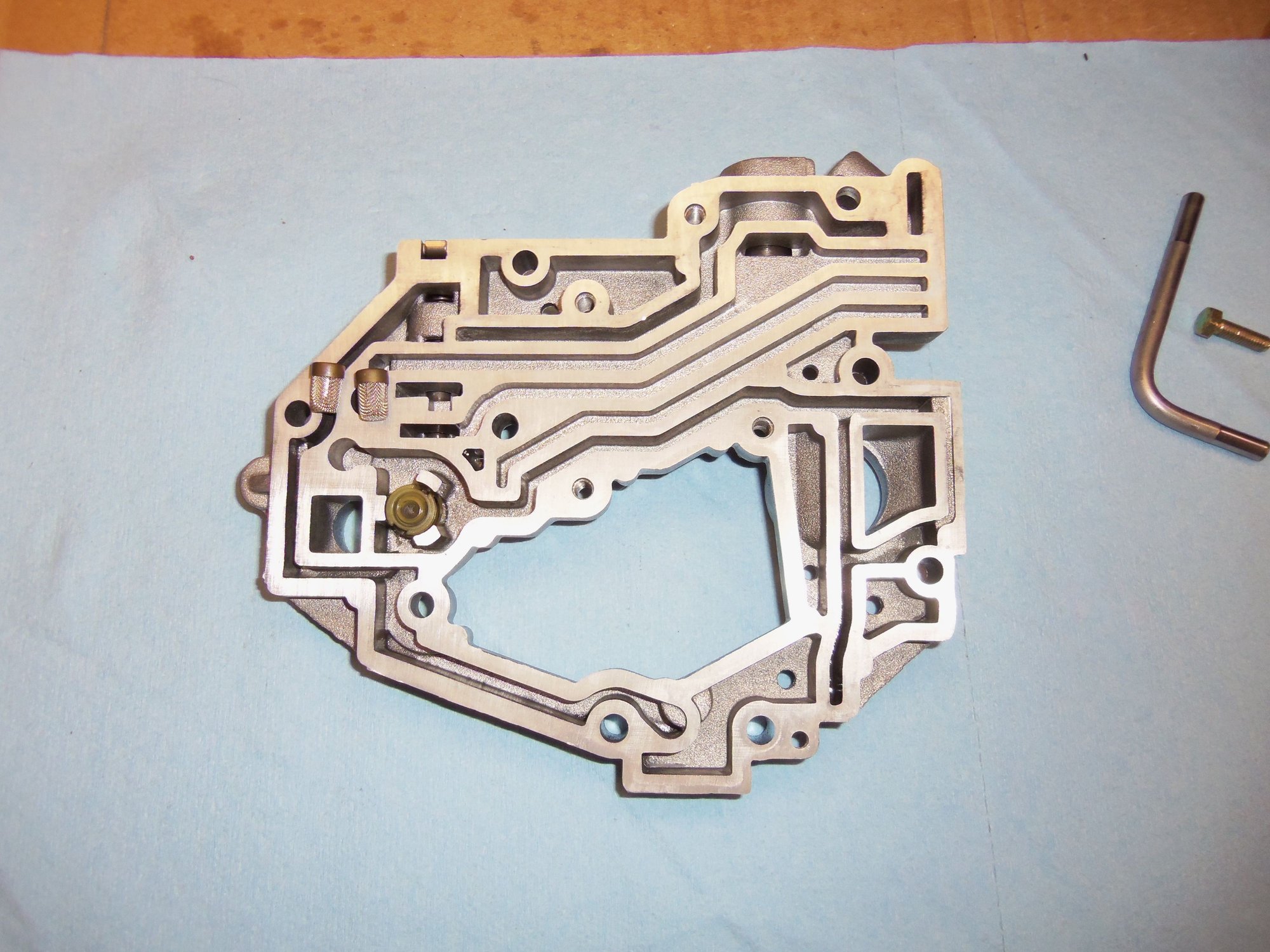
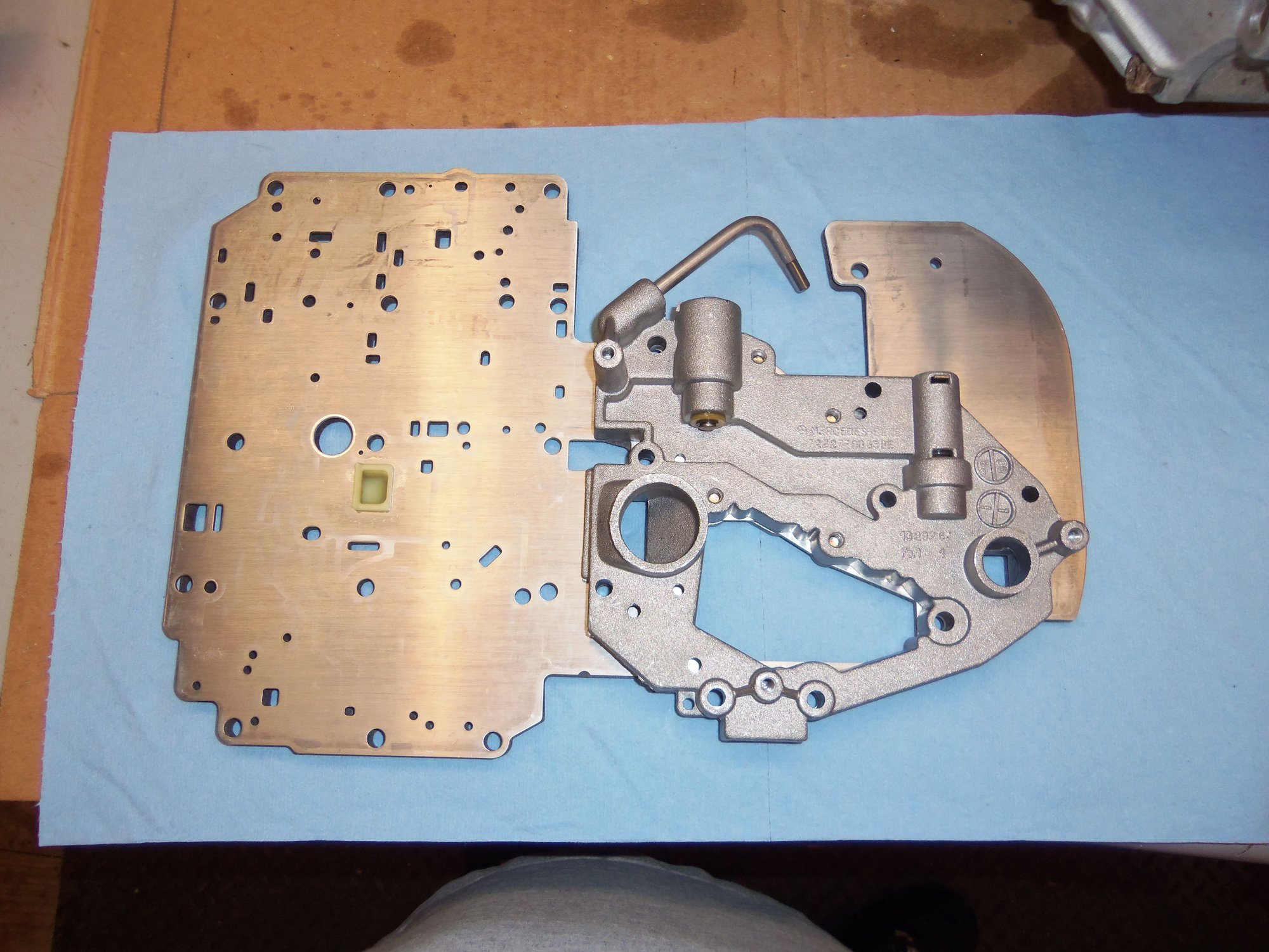
Underside of lower cover. Note the debris screens removed from their bores.
Two debris screens, removed and cleaned.
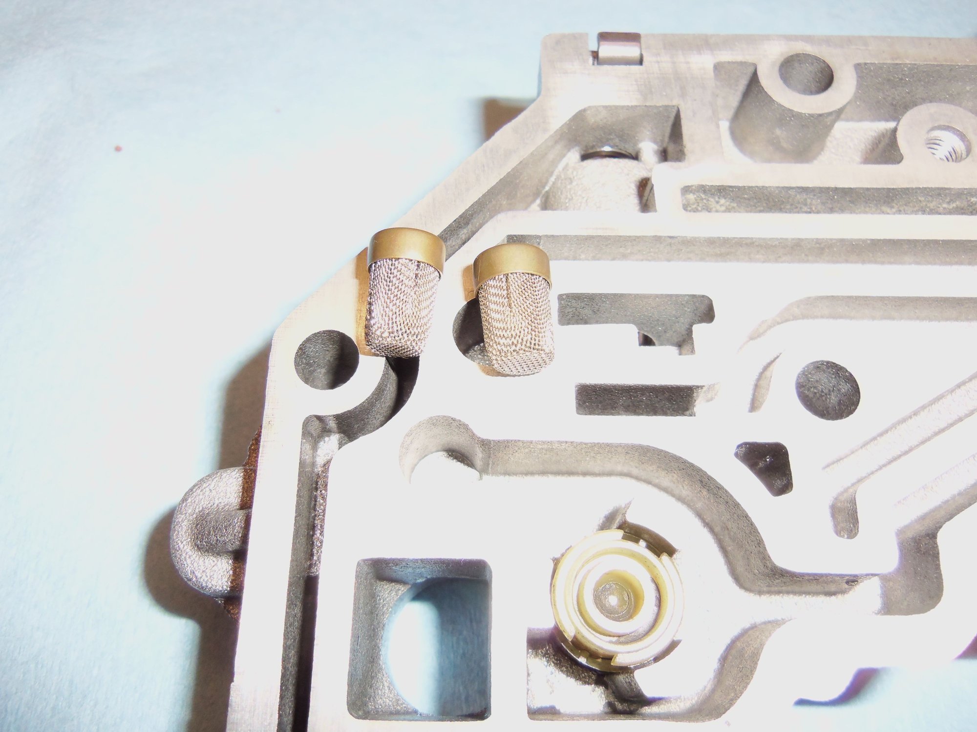
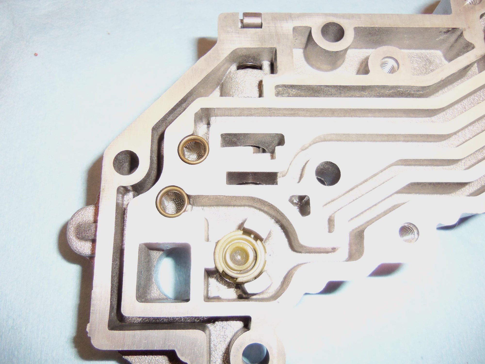
Debris screens inserted back in their bores in the lower cover.
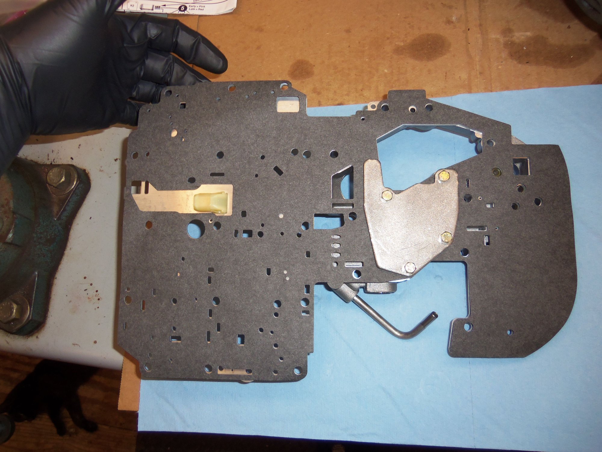
Lower cover reinstalled on separator plate with new gasket. It took a little care and patience to get the gasket, separator plate, lower cover, and reinforcing plate with all the various holes correctly lined up.
Assembled lower cover and separator plate.
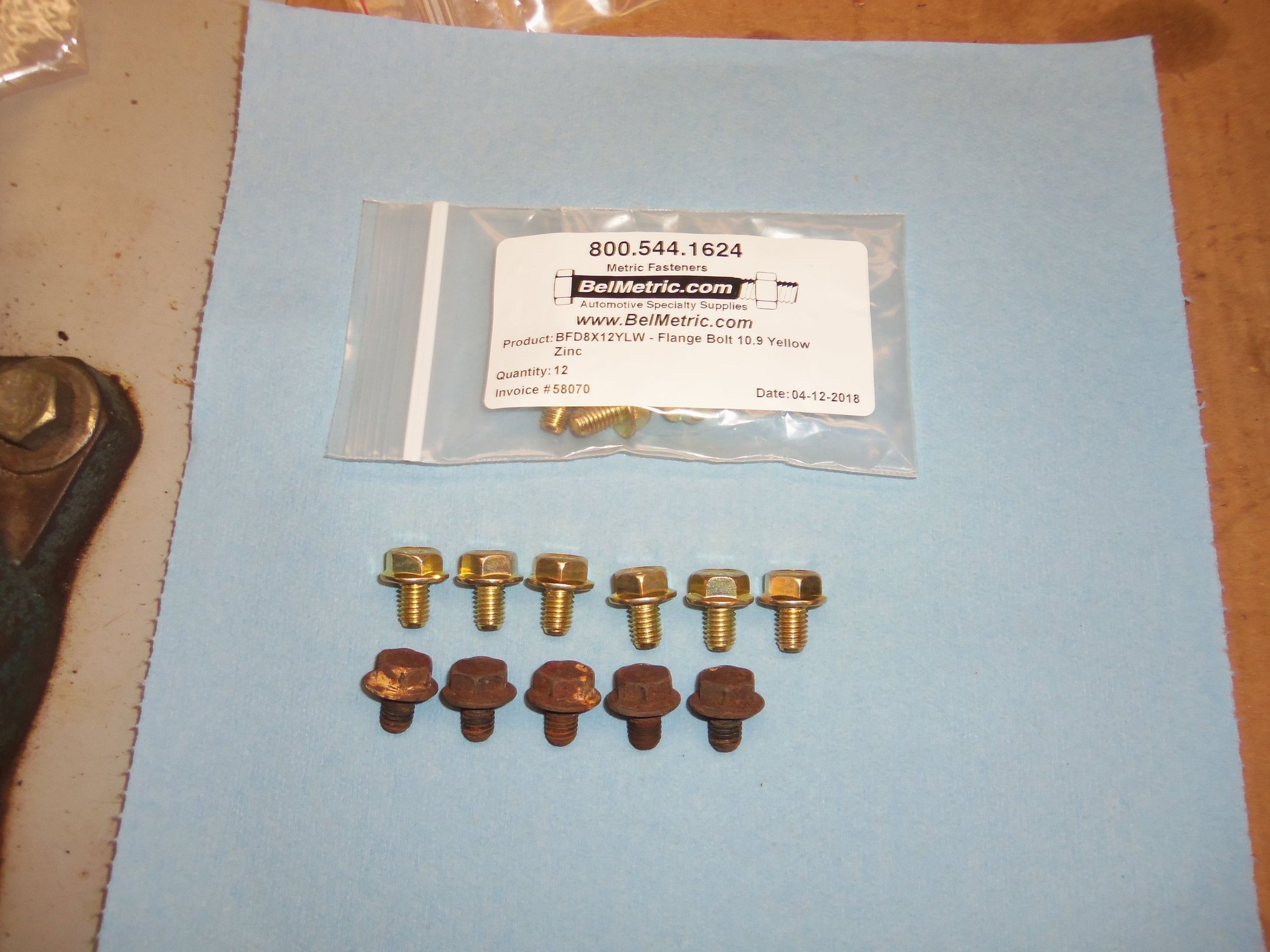
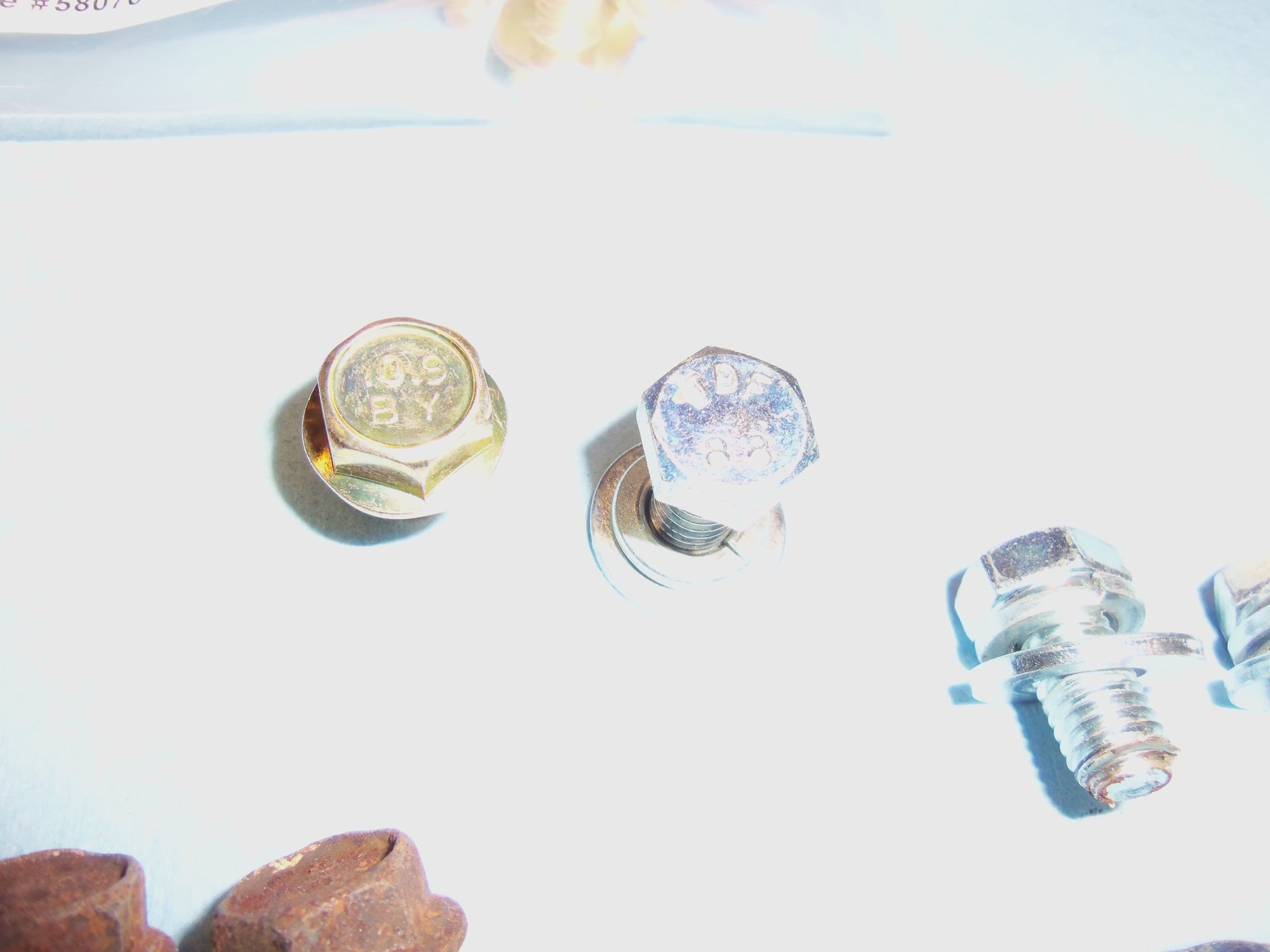
OK, need to correct an issue from reassembly of the torque converter and its drive plate. I lost one of the six M8 hex flange bolts. Besides, they were nasty and rusty. In their place, I fitted M8 hex bolts with lock and flat washers. I ordered proper replacement fasteners from Belmetric. One by one I replaced the temporary fasteners with the new hex flange bolts. Much better now!
6 new M8 x 1.25 x 12mm grade 10.9 hex flange bolts for the torque converter drive plate. Plus the original 6 bolts. I lost one...
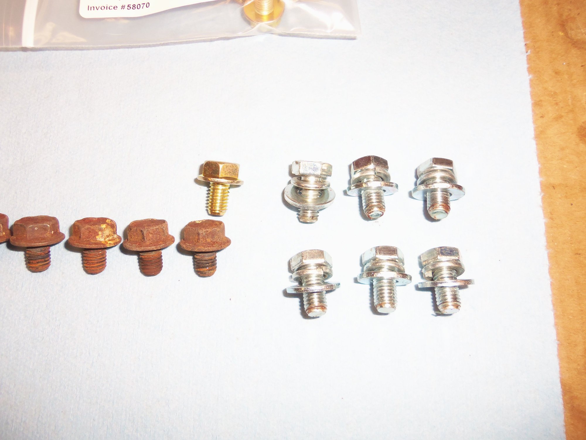
New and old hex flange bolts next to my temporary M8 x 1.25 x 15mm grade 8.8 hex bolts with lock and flat washers.
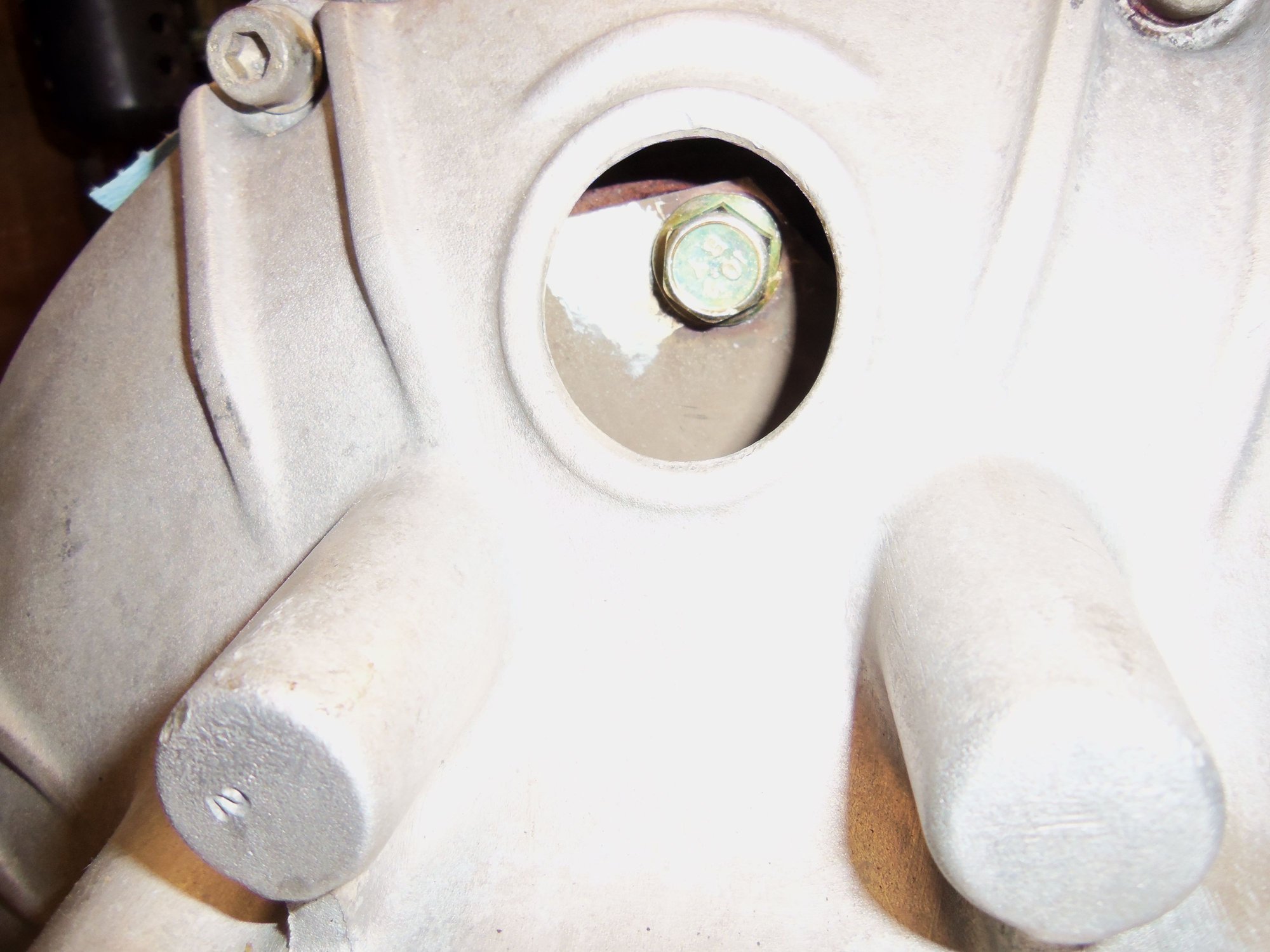
Correct hardware is now installed in the torque converter drive plate.
As I mentioned to Chris, I installed a shift kin in the valve body while it was out. This is based upon several factors:
-advice of MB/Porsche 928 experts
-advice of experienced 928 owner/technicians
-reading threads on shift kits installed in A28.** transmission on Rennlist 928
-my own personal experience with automatic transmissions
So...right off the bat: THIS IS MY OWN PERSONAL CHOICE. I have seen many posts on Rennlist 928 for and against shift kits in the A28.** transmission. I am doing it because I feel it is a good idea. Your results might vary. I think it is better to have slightly faster/crisper shifts that are better for the longevity of the clutch packs and brake bands. I do not want a soft, cushy shift. If I want a soft, imperceptible shift, I will go get the 72' Coupe DeVille I have been lusting after. Don't get me wrong. I am not trying to make this a Camaro. Though I did have one years ago. And the mullet to go with it. But, I digress. The Porsche 928 is a true GT car, not a sports car. Not a new revelation. However, I want MY 928 to feel a little more aggressive when it shifts when I put my foot in the water pump.
I have put shift kits in automatic transmissions in other vehicles I have owned over the years. They have all been positive experiences. Except the first one. We don't talk about that one. You have to be careful and understand what you are changing and what you are affecting. You have to pay attention to the selections of springs and valves in the kit. I will freely admit I went a tad too far in one setting on my Explorer. Under certain part throttle conditions, if you let out just as it shifts into 3rd, it will go into 3rd with a very noticeable hit. So, I was mindful of that in selecting how I wanted to set up the springs in the valve body of the Red Witch.
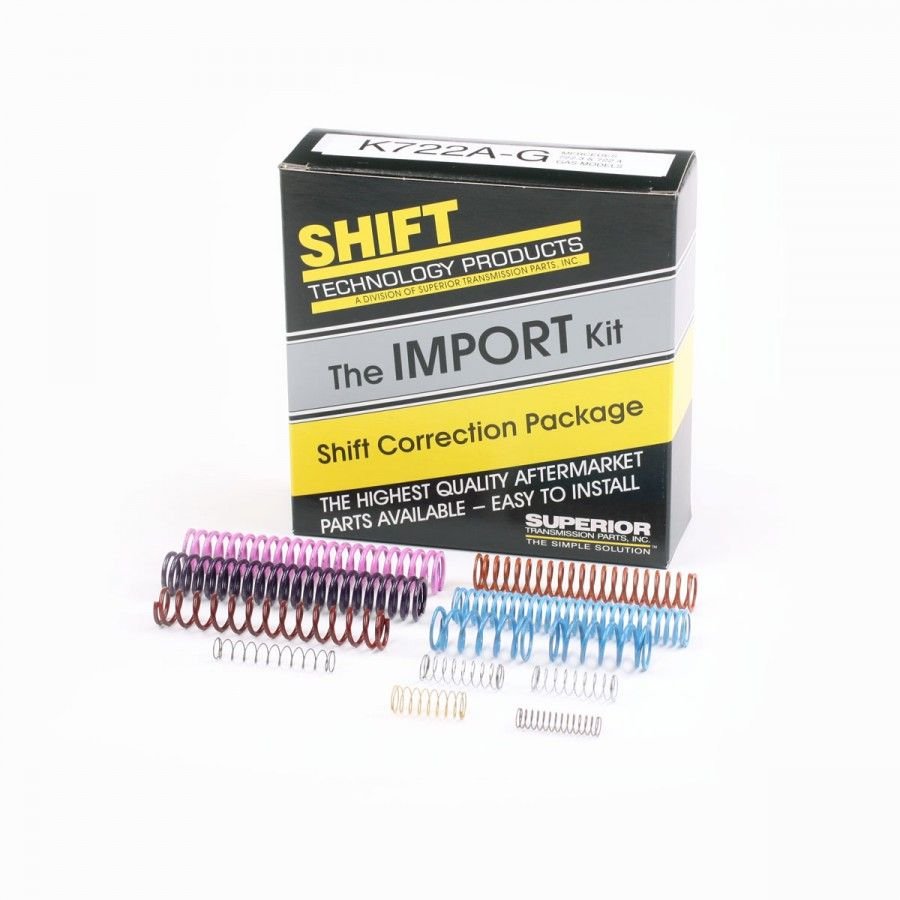
I chose the Superior K722A-G (S68165G ) Shift Correction Package.
I went with the following selections:
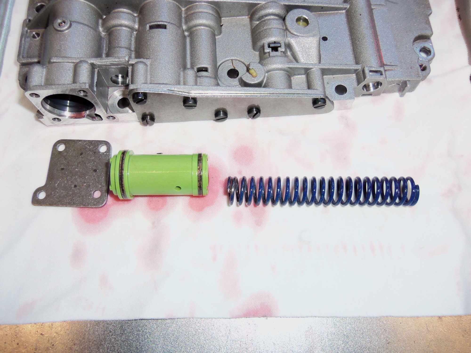
B1 1-2 shift, left stock at 'extra firm'K1 2-3 shift, removed little spring and two spring/plastic train, installed dark blue spring for 'extra firm'replaced K1 accumulator control spring with white springK2 3-4 shift, replaced the larger spring inside the green sleeve with the purple spring, left the inner spring in place inside the purple spring for 'extra firm'
replaced K2 accumulator control spring with white spring
This is a bit of a step backwards, as back in July of 2016, I replaced the K1 spring set with the updated MB spring set. The shift kit just replaced all that. It is what it is.
On that note, I have kept EVERYTHING that I removed. So, on the off chance I really screw this up. I pull the valve body again and put it back the way it was. If I REALLY screw up, I purchase a used valve body from Mark Anderson and get on Greg Brown's waiting list to have him properly rebuild and set up the valve body. No shame in trying.
Superior K722A-G shift kit.
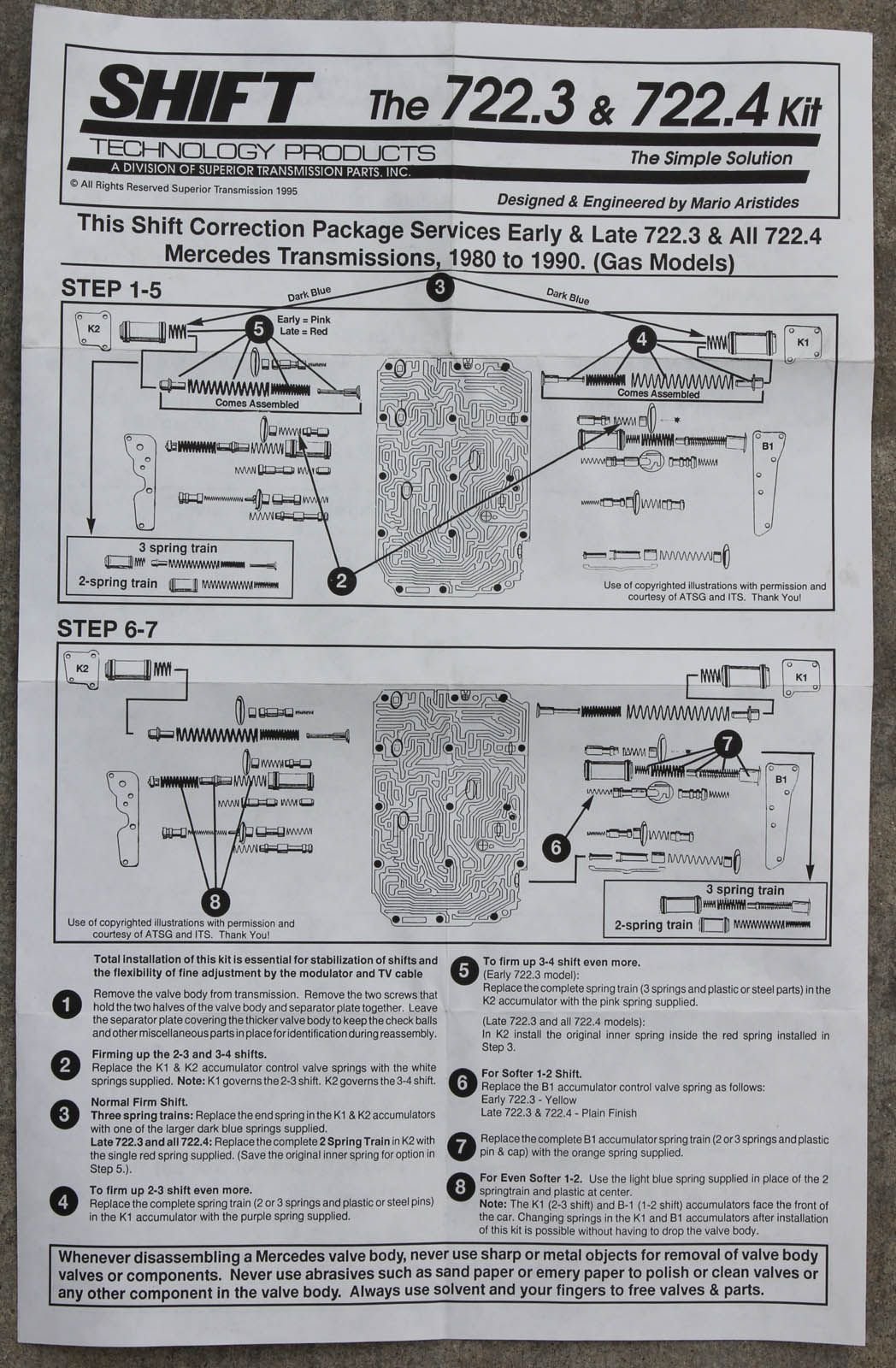
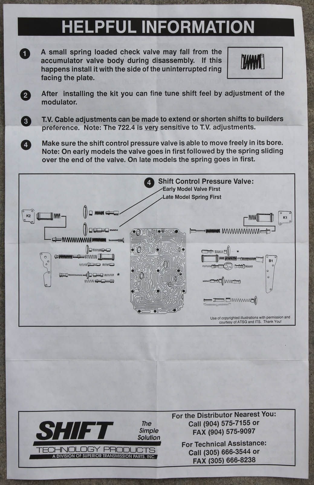
Page one of instructions.
Page two of instructions.
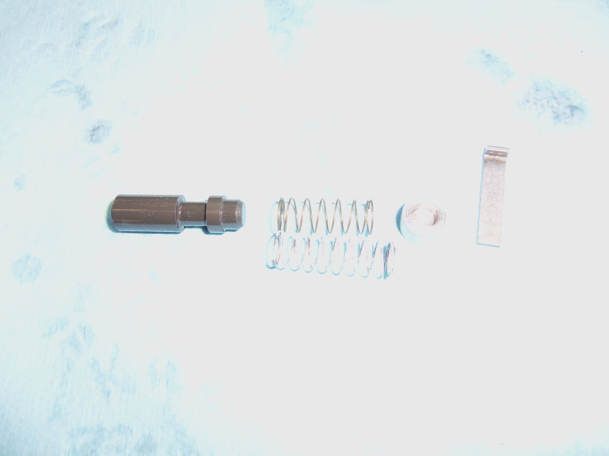
K1 accumulator control valve, spring, spring seat, and retainer. The bare metal spring inline with the valve spool is the original spring. The white spring below it is the spring from the shift kit.
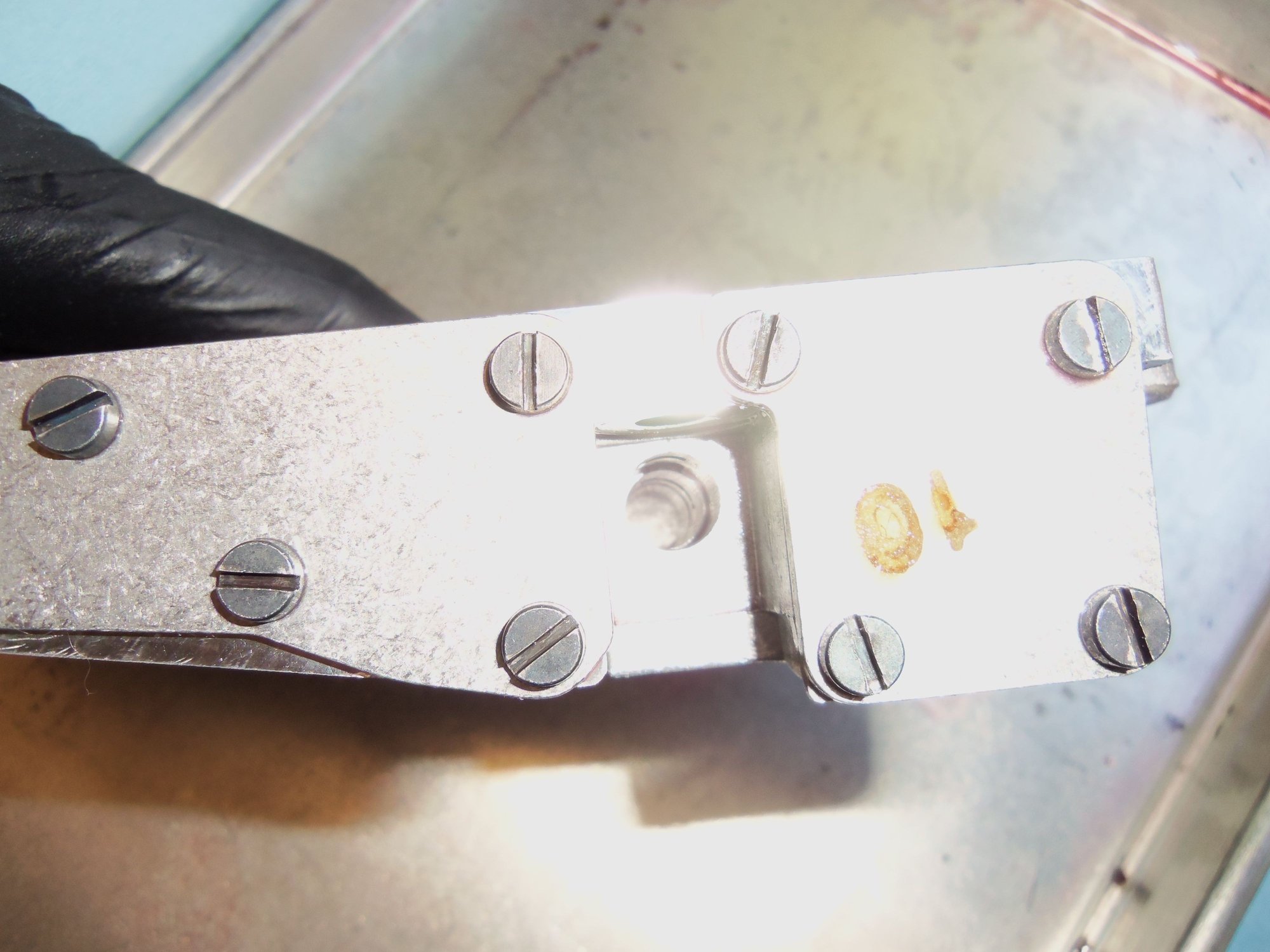
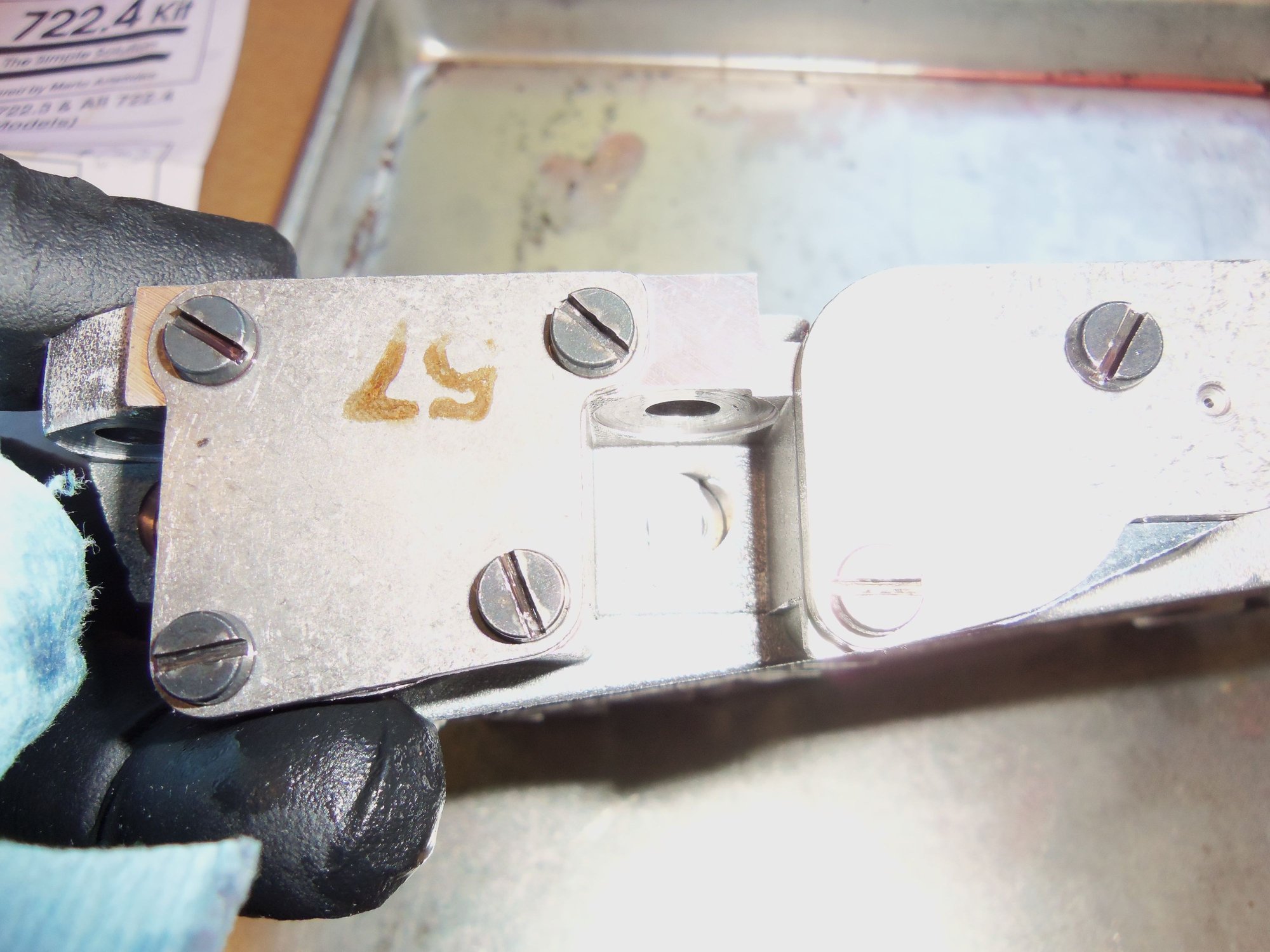
K1 accumulator control valve bore in the valve body.
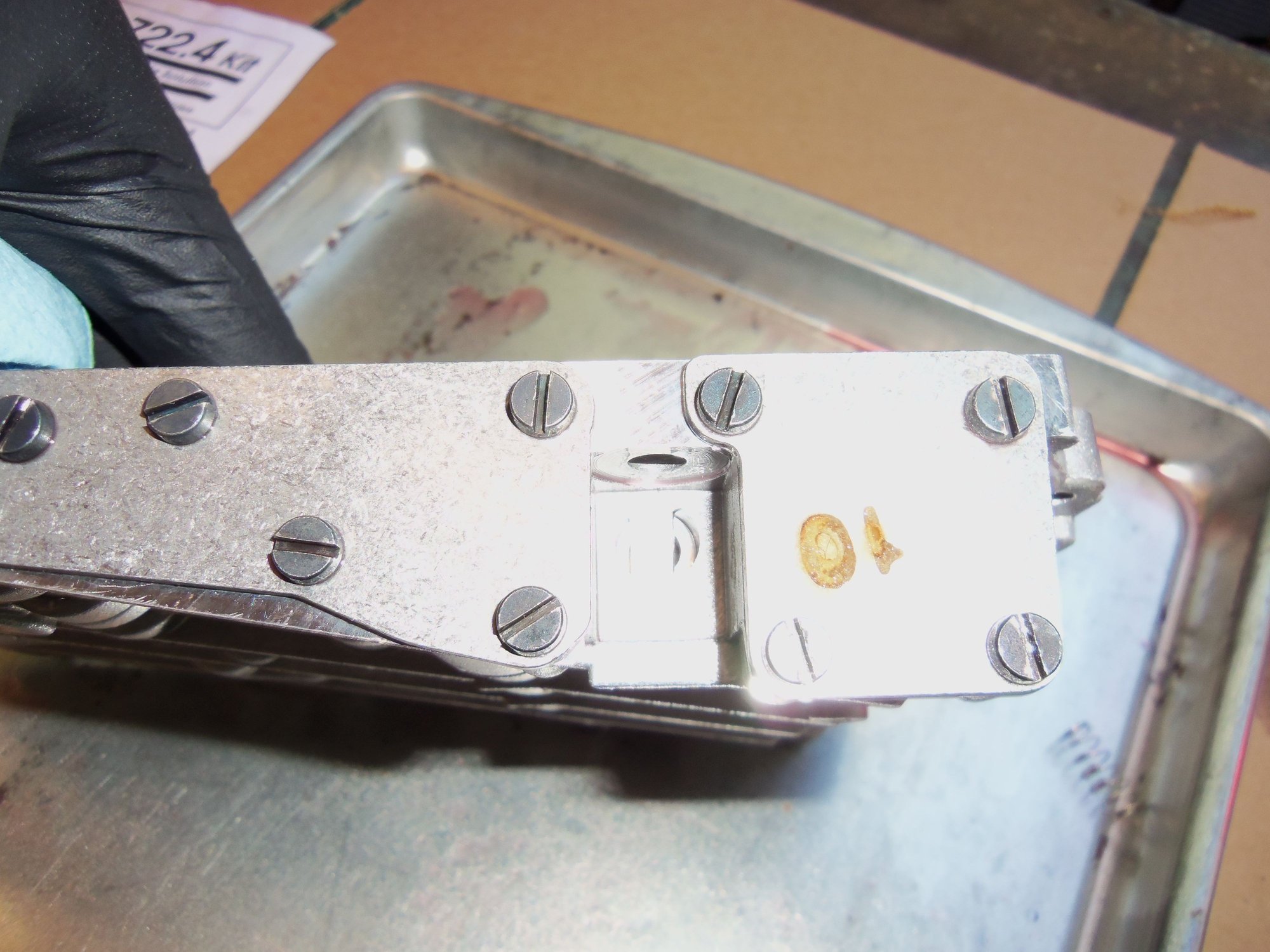
K1 accumulator control valve and retainer reinstalled in bore. Note the cookie sheet beneath the valve body to catch any loose parts that I should have already removed. None were lost.
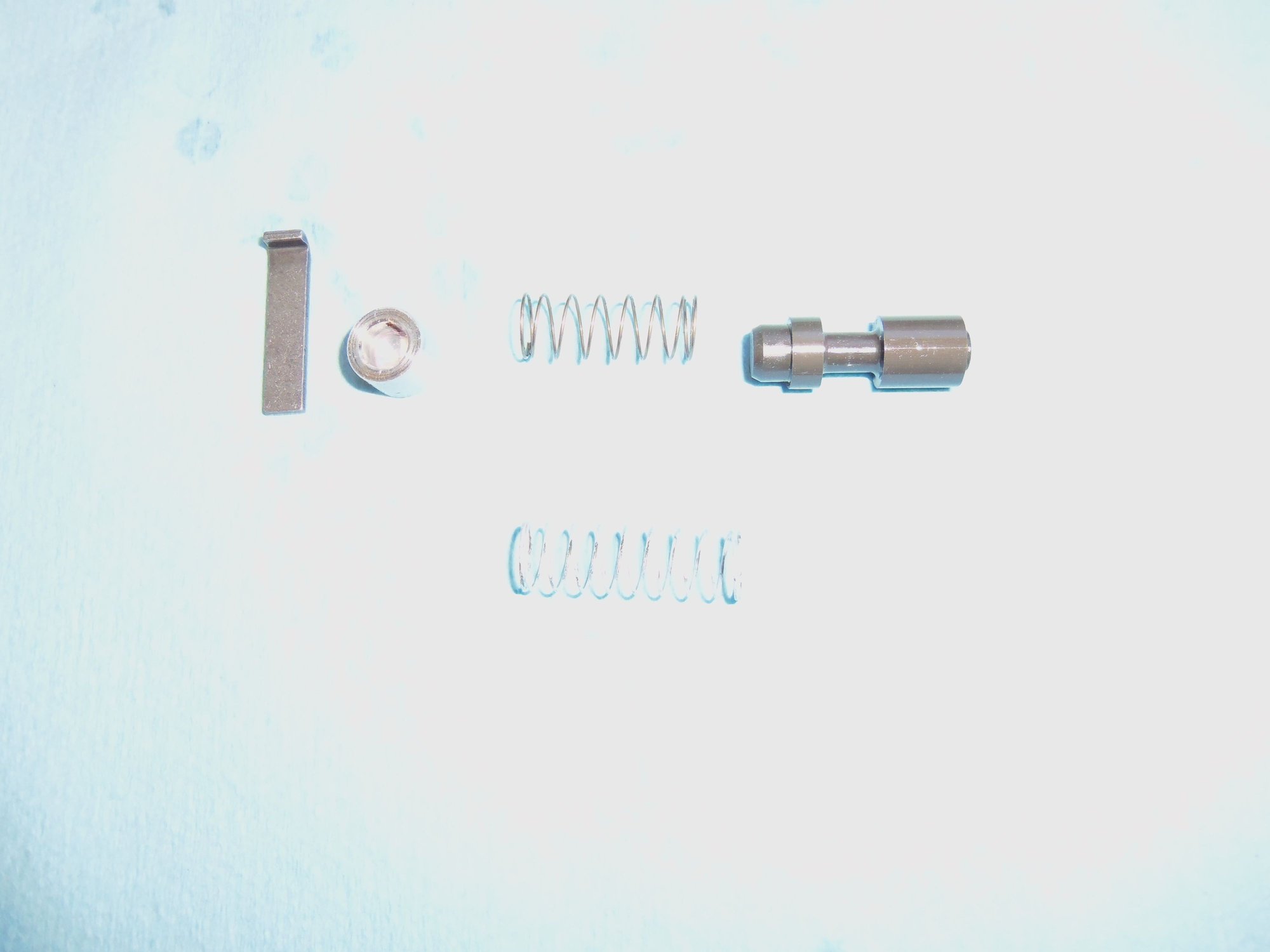
K2 accumulator control valve, spring, spring seat, and retainer. The bare metal spring inline with the valve spool is the original spring. The white spring below it is the spring from the shift kit.
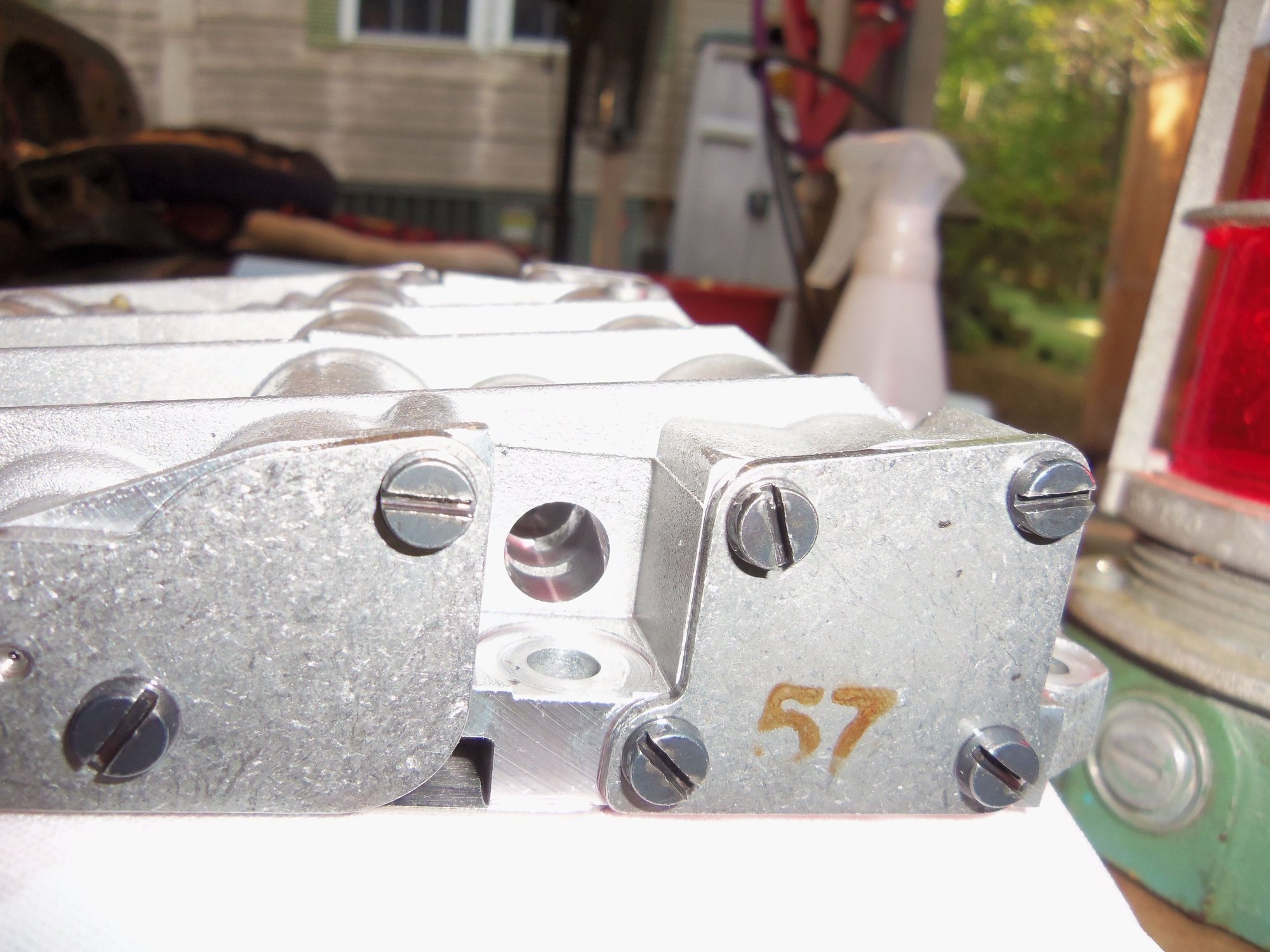
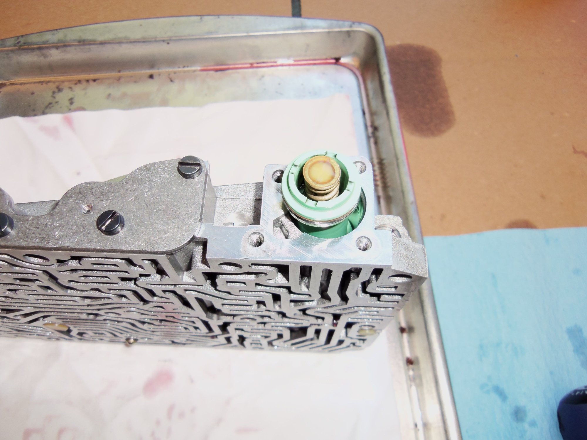
K2 accumulator control valve bore in the valve body.
K2 accumulator control valve and retainer reinstalled in bore.
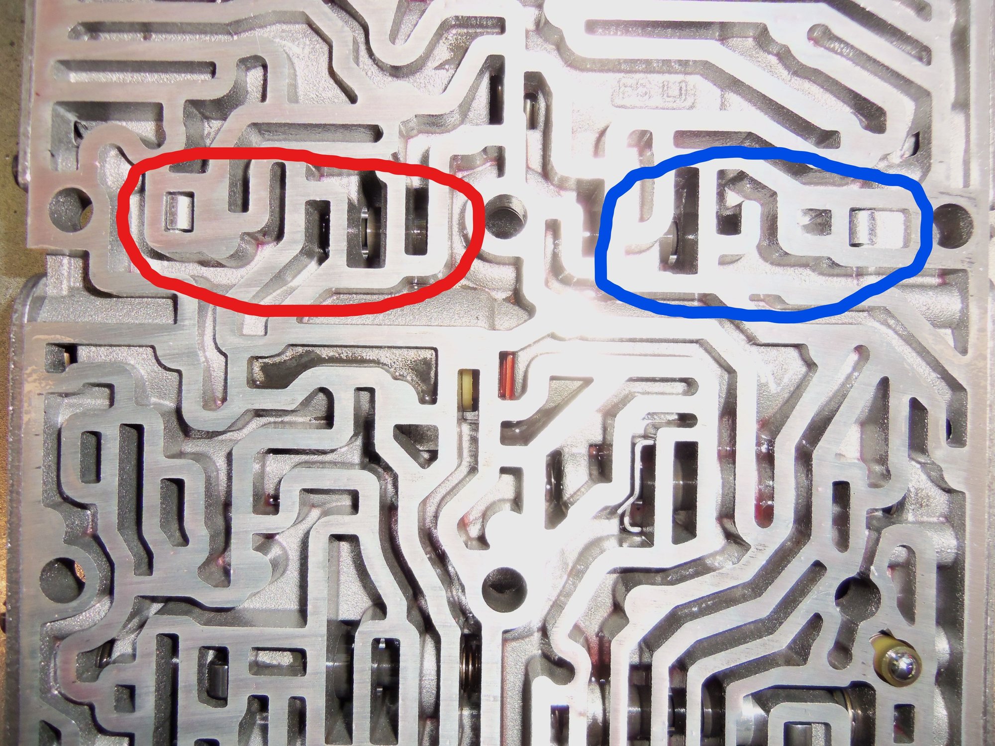
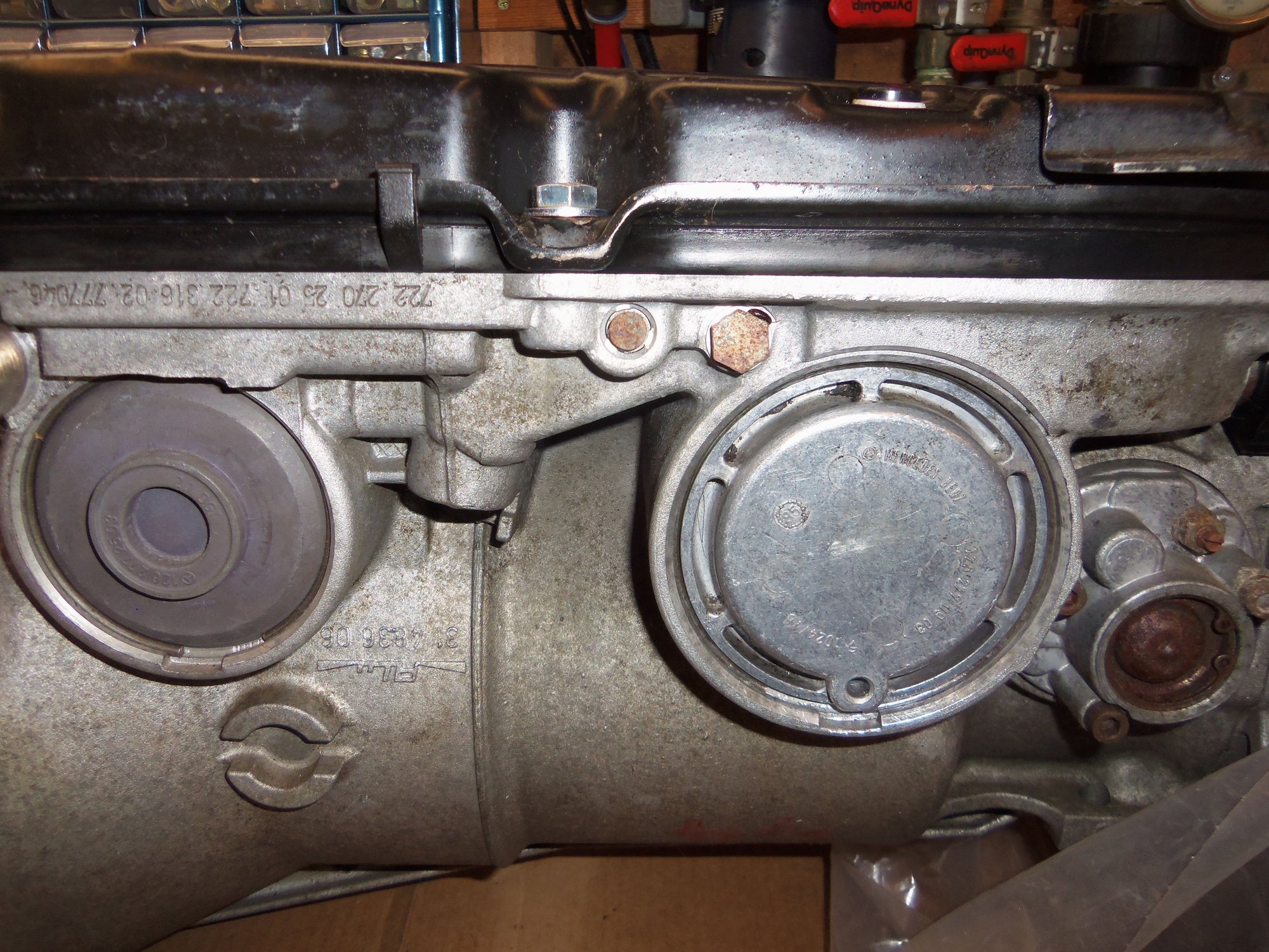
Red circle shows K2 accumulator valve and retainer, blue circle shows K1 accumulator valve and retainer. Note, the valve body has been split at this point to remove the retainers to replace these springs.
K2 accumulator. Note the lint free rags lining the cookie sheet. Need to keep clean.
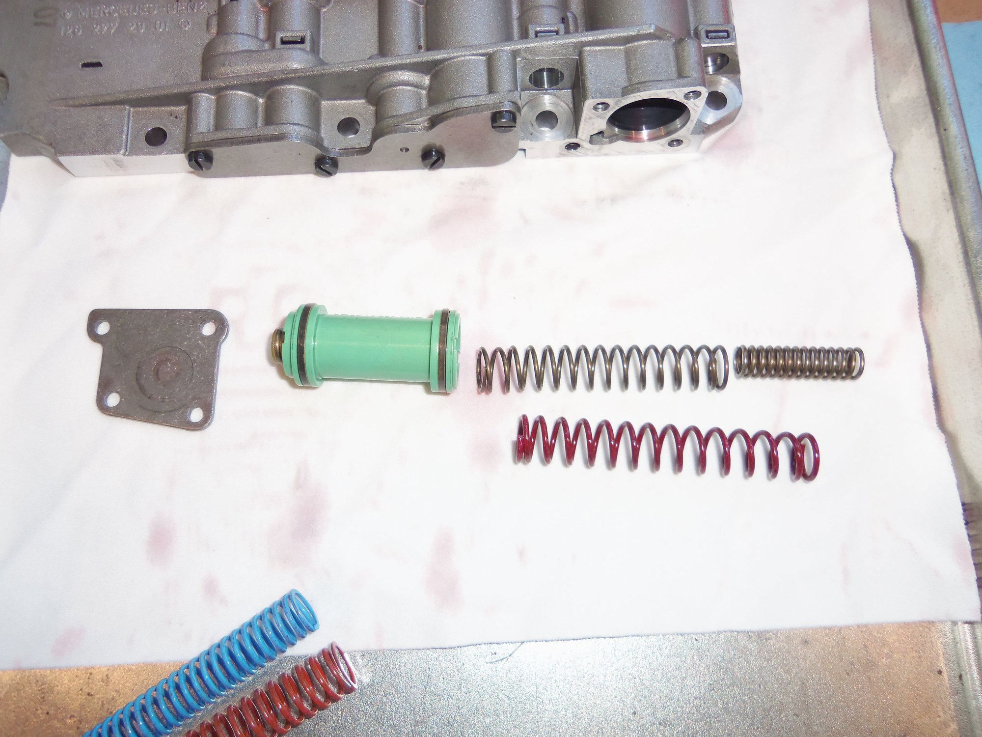
K2 accumulator spring train. Original springs on top, new purple spring from shift kit at bottom.
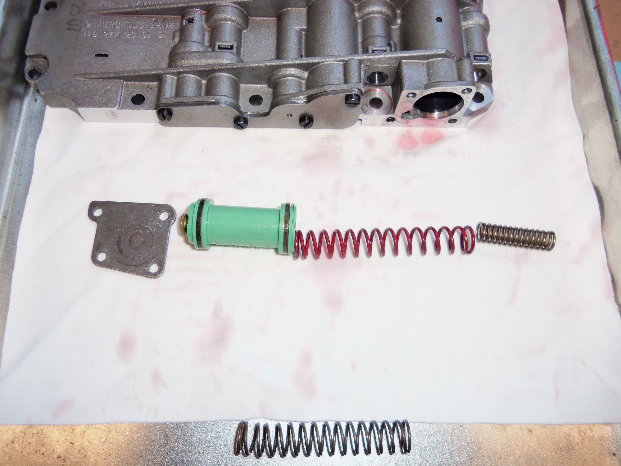
K2 accumulator with new spring in train. Original small diameter spring is inserted inside new purple spring.
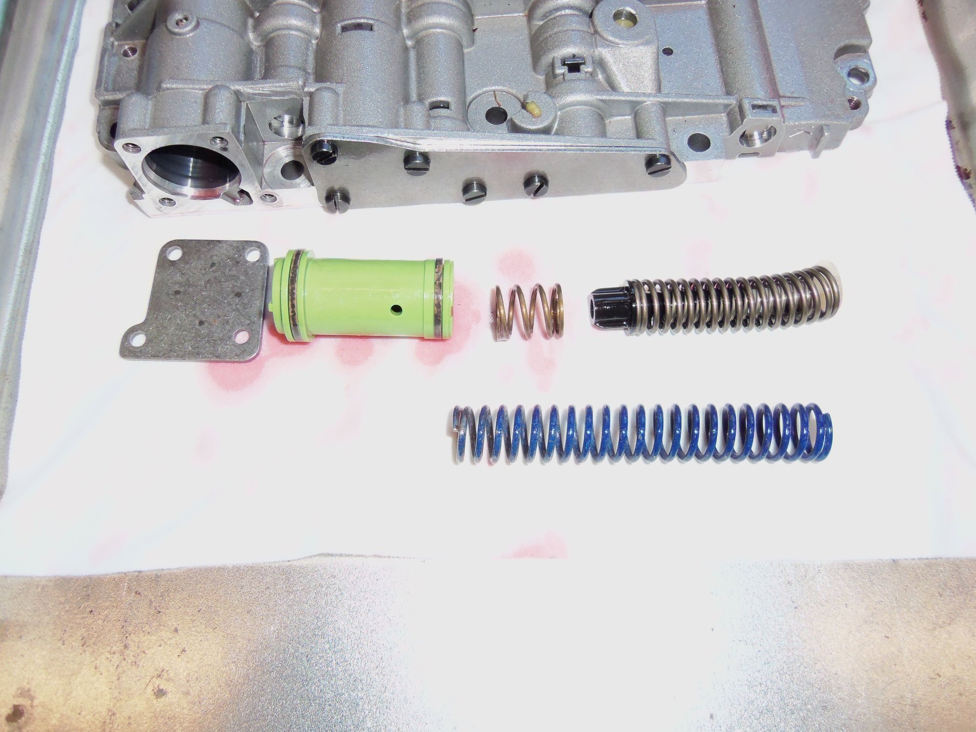
K1 accumulator spring train. Newer updated MB spring set is at top, new dark blue spring from shift kit at bottom.
K1 accumulator with new dark blue spring from shift kit completely replacing spring set.
After replacement of the various springs, the valve body was reassembled, then put in a heavy plastic bag for storage. It will be reinstalled after the other shenanigans are done on the transmission.
HA! I finally got it!
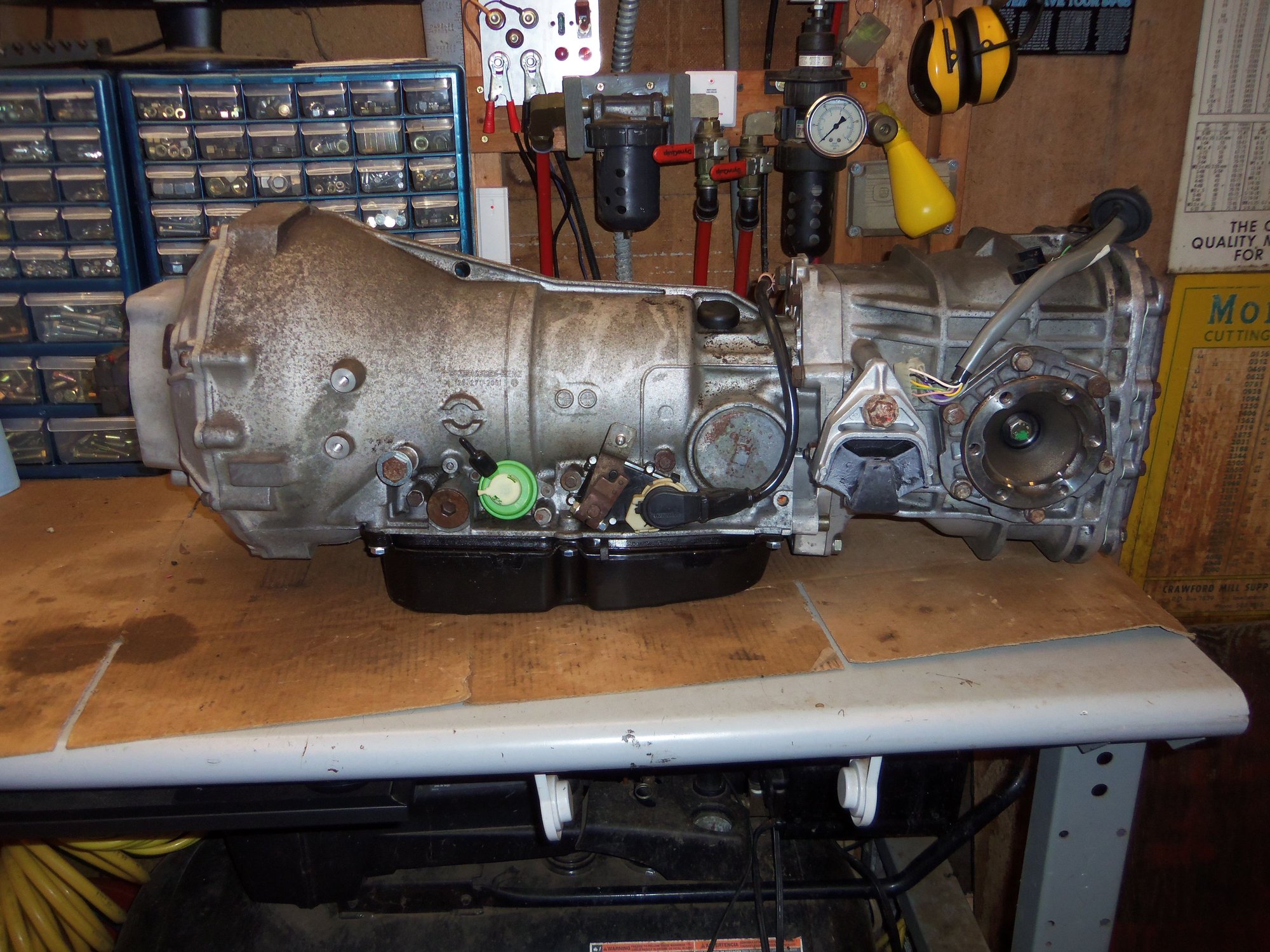
I am jumping over alot of previous work that I need to document and post, but the A28.07 automatic transmission for my Red Witch is finally done! Everything is adjusted, the transmission is reassembled, the differential is reassembled, and the wiring harness is installed.
Next step, rebuild the torque tube...
Here is my short term game plan:
-install NOS 928 Specialists performance rear anti-sway bar
-clean rear suspension cross member
-clean and rebuild the torque tube
-install cleaned bell housing to the torque tube
-marry the transmission and torque tube
-fit the transmission cooling lines, vacuum modulator line, shift cable, and Bowden cable to the trans and torque tube
-hang the transmission in the car
-install rear suspension cross member to support the transmission
Much more to do after that, but this will do for the short term.
So as not to lose track of it, I cleaned and reassembled the lower cover and separator plate, then put them in a thick plastic bag for safe keeping. They will go back on after the rest of the shenanigans are done in the transmission.
Lower cover and hardware, cleaned.
Underside of lower cover. Note the debris screens removed from their bores.
Two debris screens, removed and cleaned.
Debris screens inserted back in their bores in the lower cover.
Lower cover reinstalled on separator plate with new gasket. It took a little care and patience to get the gasket, separator plate, lower cover, and reinforcing plate with all the various holes correctly lined up.
Assembled lower cover and separator plate.
OK, need to correct an issue from reassembly of the torque converter and its drive plate. I lost one of the six M8 hex flange bolts. Besides, they were nasty and rusty. In their place, I fitted M8 hex bolts with lock and flat washers. I ordered proper replacement fasteners from Belmetric. One by one I replaced the temporary fasteners with the new hex flange bolts. Much better now!
6 new M8 x 1.25 x 12mm grade 10.9 hex flange bolts for the torque converter drive plate. Plus the original 6 bolts. I lost one...
New and old hex flange bolts next to my temporary M8 x 1.25 x 15mm grade 8.8 hex bolts with lock and flat washers.
Correct hardware is now installed in the torque converter drive plate.
As I mentioned to Chris, I installed a shift kin in the valve body while it was out. This is based upon several factors:
-advice of MB/Porsche 928 experts
-advice of experienced 928 owner/technicians
-reading threads on shift kits installed in A28.** transmission on Rennlist 928
-my own personal experience with automatic transmissions
So...right off the bat: THIS IS MY OWN PERSONAL CHOICE. I have seen many posts on Rennlist 928 for and against shift kits in the A28.** transmission. I am doing it because I feel it is a good idea. Your results might vary. I think it is better to have slightly faster/crisper shifts that are better for the longevity of the clutch packs and brake bands. I do not want a soft, cushy shift. If I want a soft, imperceptible shift, I will go get the 72' Coupe DeVille I have been lusting after. Don't get me wrong. I am not trying to make this a Camaro. Though I did have one years ago. And the mullet to go with it. But, I digress. The Porsche 928 is a true GT car, not a sports car. Not a new revelation. However, I want MY 928 to feel a little more aggressive when it shifts when I put my foot in the water pump.
I have put shift kits in automatic transmissions in other vehicles I have owned over the years. They have all been positive experiences. Except the first one. We don't talk about that one. You have to be careful and understand what you are changing and what you are affecting. You have to pay attention to the selections of springs and valves in the kit. I will freely admit I went a tad too far in one setting on my Explorer. Under certain part throttle conditions, if you let out just as it shifts into 3rd, it will go into 3rd with a very noticeable hit. So, I was mindful of that in selecting how I wanted to set up the springs in the valve body of the Red Witch.
I chose the Superior K722A-G (S68165G ) Shift Correction Package.
I went with the following selections:
B1 1-2 shift, left stock at 'extra firm'K1 2-3 shift, removed little spring and two spring/plastic train, installed dark blue spring for 'extra firm'replaced K1 accumulator control spring with white springK2 3-4 shift, replaced the larger spring inside the green sleeve with the purple spring, left the inner spring in place inside the purple spring for 'extra firm'
replaced K2 accumulator control spring with white spring
This is a bit of a step backwards, as back in July of 2016, I replaced the K1 spring set with the updated MB spring set. The shift kit just replaced all that. It is what it is.
On that note, I have kept EVERYTHING that I removed. So, on the off chance I really screw this up. I pull the valve body again and put it back the way it was. If I REALLY screw up, I purchase a used valve body from Mark Anderson and get on Greg Brown's waiting list to have him properly rebuild and set up the valve body. No shame in trying.
Superior K722A-G shift kit.
Page one of instructions.
Page two of instructions.
K1 accumulator control valve, spring, spring seat, and retainer. The bare metal spring inline with the valve spool is the original spring. The white spring below it is the spring from the shift kit.
K1 accumulator control valve bore in the valve body.
K1 accumulator control valve and retainer reinstalled in bore. Note the cookie sheet beneath the valve body to catch any loose parts that I should have already removed. None were lost.
K2 accumulator control valve, spring, spring seat, and retainer. The bare metal spring inline with the valve spool is the original spring. The white spring below it is the spring from the shift kit.
K2 accumulator control valve bore in the valve body.
K2 accumulator control valve and retainer reinstalled in bore.
Red circle shows K2 accumulator valve and retainer, blue circle shows K1 accumulator valve and retainer. Note, the valve body has been split at this point to remove the retainers to replace these springs.
K2 accumulator. Note the lint free rags lining the cookie sheet. Need to keep clean.
K2 accumulator spring train. Original springs on top, new purple spring from shift kit at bottom.
K2 accumulator with new spring in train. Original small diameter spring is inserted inside new purple spring.
K1 accumulator spring train. Newer updated MB spring set is at top, new dark blue spring from shift kit at bottom.
K1 accumulator with new dark blue spring from shift kit completely replacing spring set.
After replacement of the various springs, the valve body was reassembled, then put in a heavy plastic bag for storage. It will be reinstalled after the other shenanigans are done on the transmission.
Well....it will shift abruptly and very hard.
There will be absolutely no original "soft" feeling, where you need to watch the tach, to know that it just shifted....your neck snapping back will tell you it just shifted.
Thanks, Greg. I understand.
That is why I kept and labeled all the original parts that came out of this valve body.
If I decide the transmission shifts too hard, I will go back into the valve body and take care of it.
Shift linkage rod where it connects to the shift shaft.
Tiny E-clip that secures the shift linkage rod.
B2 brake band plastic guide.
B2 brake band plastic guide.
B2 brake band, this is the cast iron support.
B2 brake band pressure piston, anchor at the opposite side as the B2 servo piston.
Band up against the steel bushing for the servo piston.
Jack screw and socket to remove the seal and steel bushing.
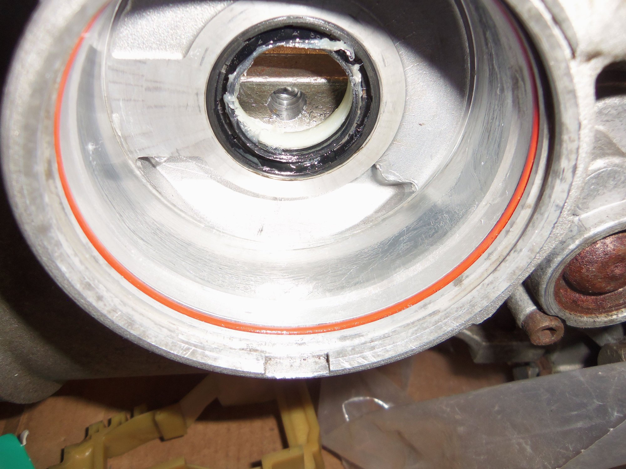
Bushing and seal bore, from the servo piston side.
Bore from the band side.
New nylon bushing and new seal on the left, old steel bushing and old seal on the right.
Nylon bushing installed, from the servo piston side.
Nylon bushing, from the band side.
Test fit the new B2 servo piston assembly.
B2 pressure pin into the band.
While I was in there, I wanted to replace the shift linkage shaft seal. So, out it came. I was concerned about alignment of the detent 'comb' on the shaft. Turns out it is a D shaped shaft, no worries about alignment. I removed the seal by prying it out with a small screw driver. I attempted to install the new seal with a jack screw. No good. So, I carefully tapped it into place.
Shift shaft and detent 'comb'.
Better view of detent 'comb'.
Assembly separated.
Double D shaped hole in detent 'comb' means no alignment issues with shaft.
Bore in case for shift shaft.
Shift shaft seal on outside of case.
New seal.
Front of new seal at left and old seal at right. Old seal shows scars of 'gentle' removal efforts.
Back side of seal showing lip, new at left, old at right.
Jack screw nut in case.
Failed attempt to install new seal with jack screw. Note incorrect angle of seal ring.
New seal carefully tapped into place. Distortion on seal is petroleum jelly for lubrication.
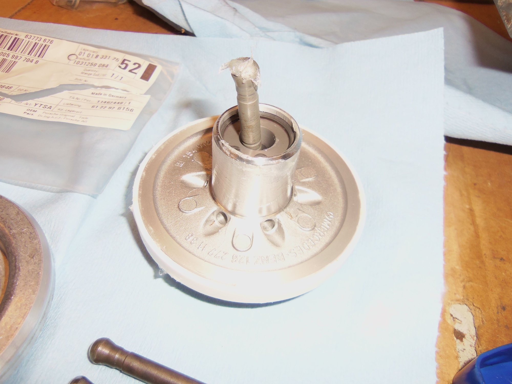
Next was the B1 servo piston. On the advice of an old-school Mercedes Master Mechanic with way too much transmission experience, I fitted a later, self-adjusting B1 servo piston assembly. It was a direct drop in, though I had to order the matching plastic guide as well.
Self-adjusting B1 servo piston assembly: Mercedes A 124 270 12 32
Matching plastic guide: Mercedes A 140 277 10 40
Because I don't have a deep throat sliding clamp, I had to get creating with a set of 'cauls'. I learned of this from a woodworking friend. My set up was sketchy, but it worked. The springs for the B1 servo piston are no sh*t strong! I got it, though.
My sketchy rig with 'cauls' (lengths of wood) and two sliding jaw clamps.
Large socket pressing against B1 servo piston cover to allow removal of the circlip.
Circlip and B1 servo piston/spring assembly removed.
B1 servo piston plastic guide in place in the case.
Guide removed.
Guide removed.
B1 servo piston guide bore in the case.
Bore with seal removed.
B1 servo piston cover seal.
Double springs removed from the B1 servo piston.
Business end of the piston.
Business end of the piston.
Servo cover.
Servo cover. It is NOT sheetmetal, but much stouter.
Updated B1 self-adjusting servo piston, guide, and cover seal.
New on left, old on right. Note new uses a teflon sealing ring, while the old used a rubber lip seal.
Business ends of the pistons.
Old guide on the left, new on the right.
Old guide on the left, new on the right.
Old piston in its guide on the left, new on the right.
New guide and seal in the bore.
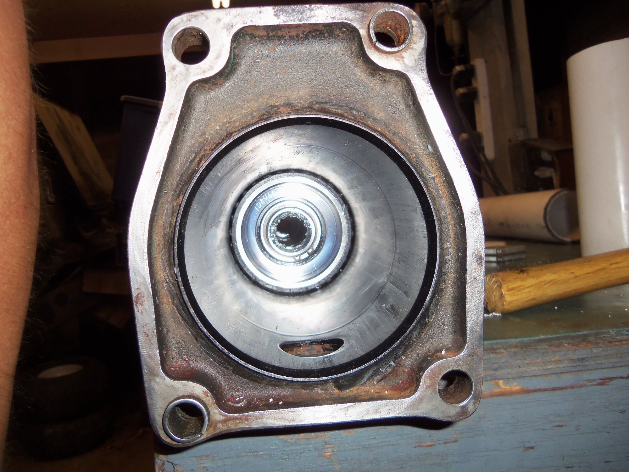
View of the new guide through the valve body side of the transmission case.
Springs on the servo piston.
Updated B1 servo piston installed.
Just barely see the piston through the guide.
Now, back to the elephant in the room. I had issues setting B2 brake band clearance, to say the least. I am ashamed to admit it took me WAY too long, to the point it became a mental block for me. Biggest problem was getting precision measurements. I could not get the same thing for any length of time. My measurements were all over the place. Not conducive to getting it right. Main issue was calipers. WSM shows deep throat internal jaw calipers. All my calipers were deep throat external jaw. The way the B2 band support is cast, external jaws will not register properly. I went through various cockamamie schemes and set-ups using different calipers and vernier adjustable scribes. Nothing worked, nothing was repeatable. I finally bought a set of deep jaw external calipers and ground/filed/mangled the tips until they did what I wanted. Even then, it took a few tries to get the tips as such where I could get repeatable results.
In with this mess, I was having issues with the adjusting pins for the band. The way you adjust the band is with different length pins. You measure the existing clearance, then select a pin of length that will give you the target clearance. According to the WSM Volume 3, section 37, page 171, clearance should be 6 - 7mm. I later learned that this spec had been revised to 5.5 - 5.7mm.
Early in this process, I measured B2 brake band at 10.56mm, with the factory pin of 47.1mm length. So, to get to the target clearance, I would need a pin of 51.5mm lenght. Too bad the pins were either 51.0 or 52.5mm. I ordered the 52.5mm pin and had my machinist shorten it to 51.5mm and round the ends to match the factory pin. Simple enough.
No. With the 51.5mm pin installed clearance went to 5.16mm. Not what was calculated. I immediately suspected my measuring efforts were faulty. This began the downward spiral into madness.
Finally, a couple of weeks ago, I was able to get precise, repeatable measurements. B2 brake band clearance with the original 47.1mm pin was 10.35mm. No longer trusting the modified 52.5mm pin(which I further mangled), I had ordered a new 51.0mm pin. With this pin installed, B2 clearance was 6.35mm. Installing a 52.5mm pin would result in clearance being too tight, in the high 4.9mm range. I conferred with the Mercedes tech again. He told me 6.35mm was fine for a used band and used drum. And...it is a helluva lot better than 10.35mm!
WSM Volume 3, Section 37, page 170. Deep throat internal jaw calipers to measure B2 brake band clearance.
Original 47.1mm pin at top, new 52.5mm pin at bottom.
52.5mm pin shortened to 51.5mm.
Ground down ends rounded off.
47.1mm pin at top, mangled 52.5mm pin middle, new 51.0mm pin at bottom.
Some, but not all of the various calipers I tried to make work. Bottom set finally did it. Top set was laughable, but I was desperate.
Properly measuring B2 brake band clearance. Finally.
Onto reassembly of the transmission and differential!!!
What a great "how to" for us DIYers! Thanks for the exceptional photo documentary Seth, this is epic!
I don't relish the idea now, but when I move into my new shop I think I'll follow in your footsteps and rebuild my spare using these instructions. Really awesome job and a real credit to you. Good luck on the TT rebuild. I did mine on the 944 using Constantine's bearings and it came out great.
With all of the madness of setting B2 brake band clearance behind me, I could reassemble the transmission and differential.
I reinstalled the B2 servo piston for the last time, with a new cover seal. Followed by reinstallation of the brake band guide, and the shift linkage rod to the shift shaft. Moment of anxiety as I fit the tiny E-clip so as not to drop it.
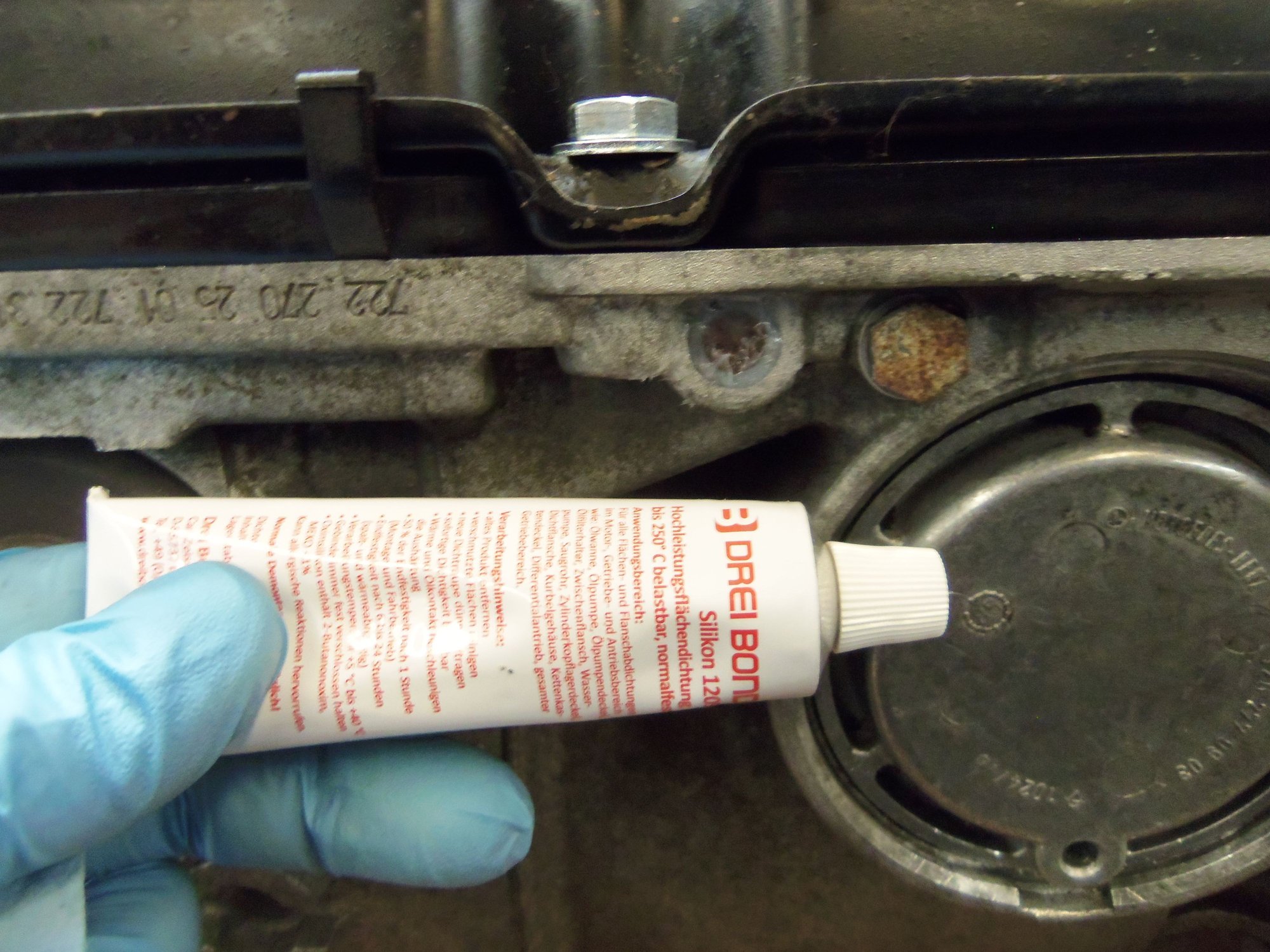
Next was a little tip I read about on Rennlist in the past from Greg Brown. I cleaned the end of the TV lever shaft in its bore on the outside of the transmission case. Once dry, I liberally coated it with DreiBond. This will prevent any leaks in the future.
Then, reinstall the transmission filter and reinstall the pan. Being VERY careful to torque the new pan bolts to 8Nm in stages.
B2 servo piston components.
Cover seal and radial seal, in place and lubricated with petroleum jelly.
51.0mm pressure pin seated in the servo piston, ends of the pin and the piston teflon seal coated with petroleum jelly.
Updated B1 and B2 servo pistons installed. Finally.
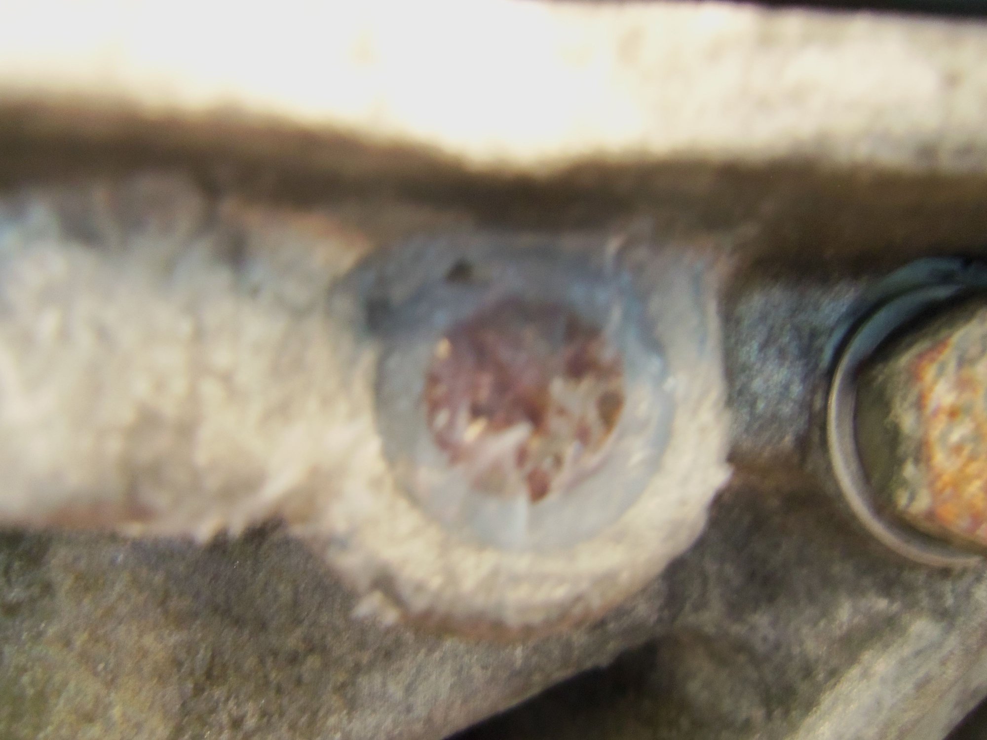
TV lever shaft in its bore in the case.
DreiBond for the win!
Too much is just enough. Don't want it to leak.
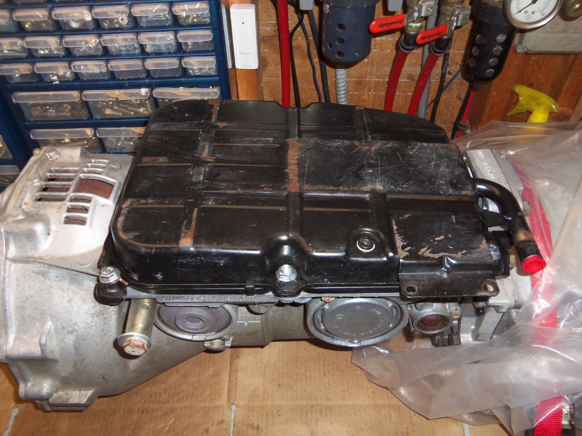
Transmission pan is back on. Not to come off for another 1000 miles.
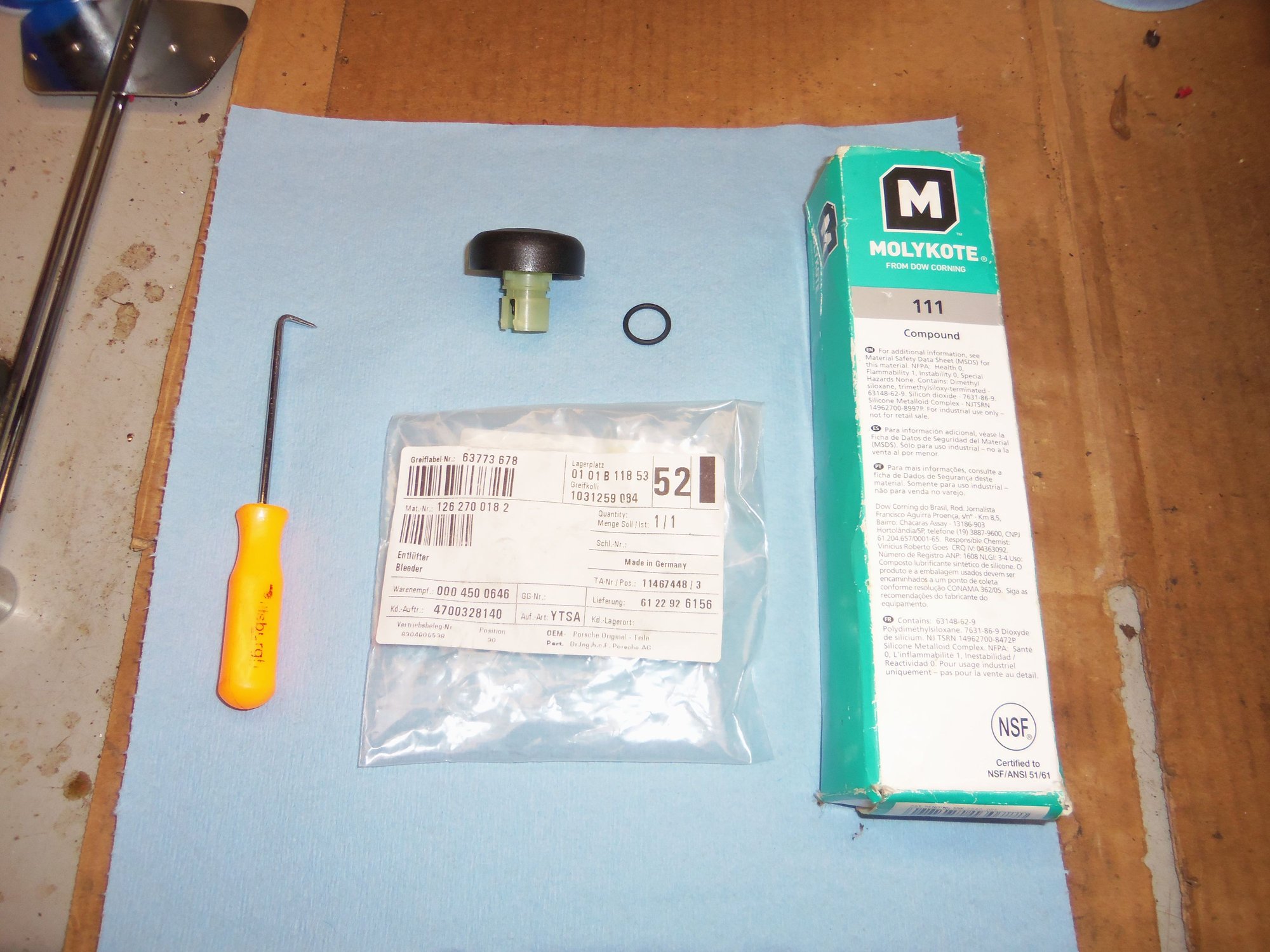
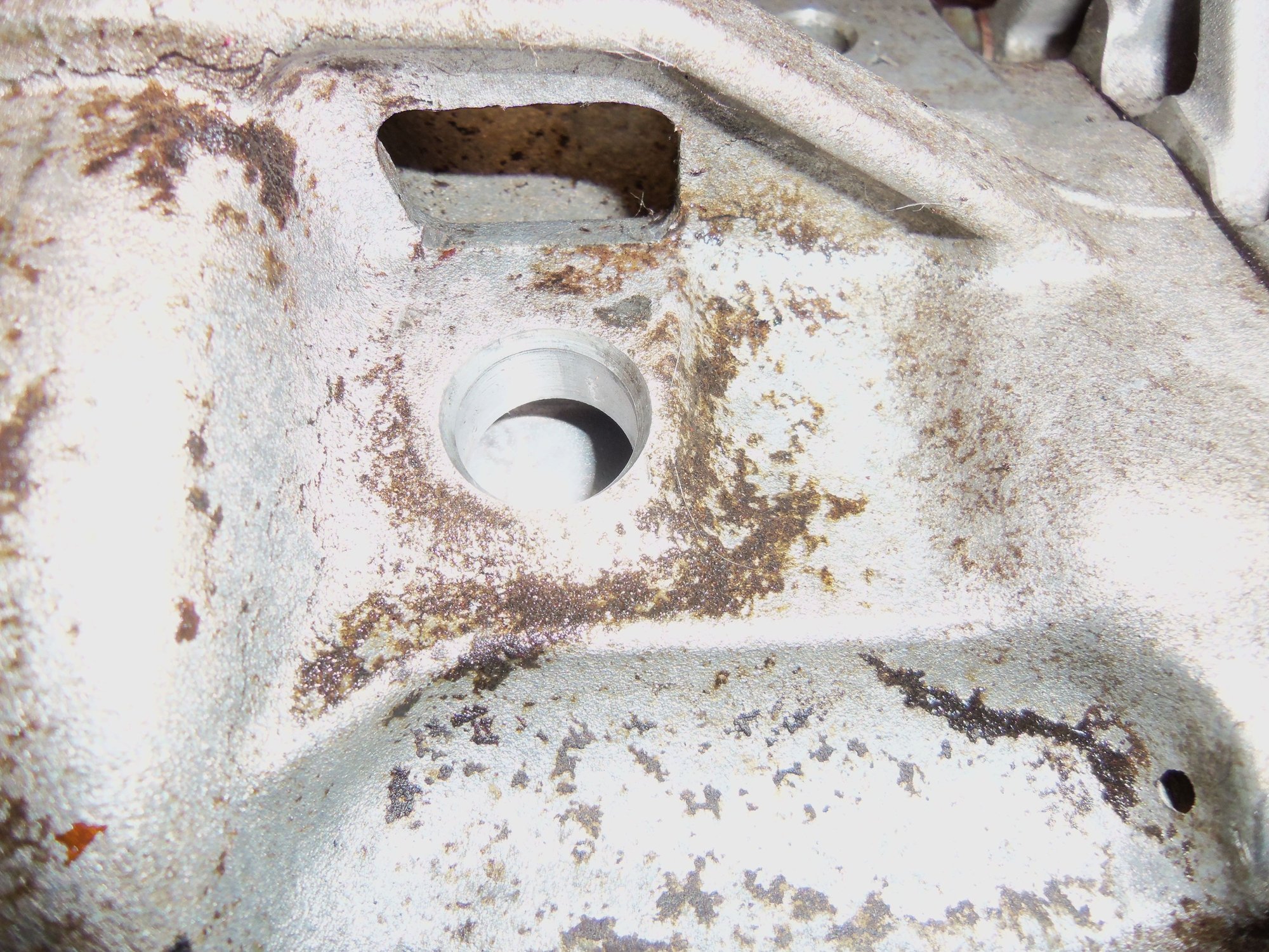
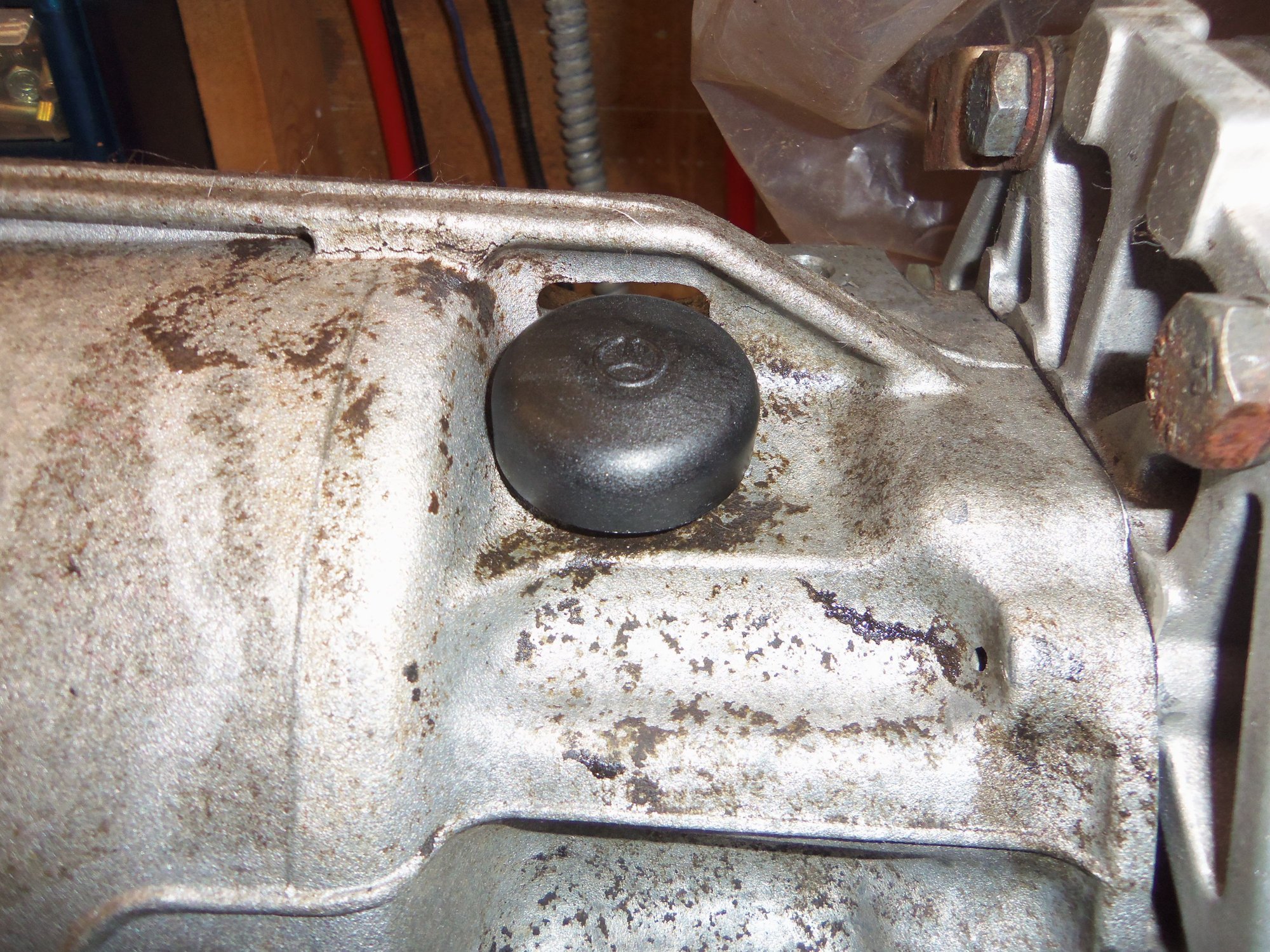
With the pan back on, I rolled the transmission back over so it was right side up. Last thing for the transmission was to install the new case vent seal and O-ring. I lubricated the O-ring with Dow 111.
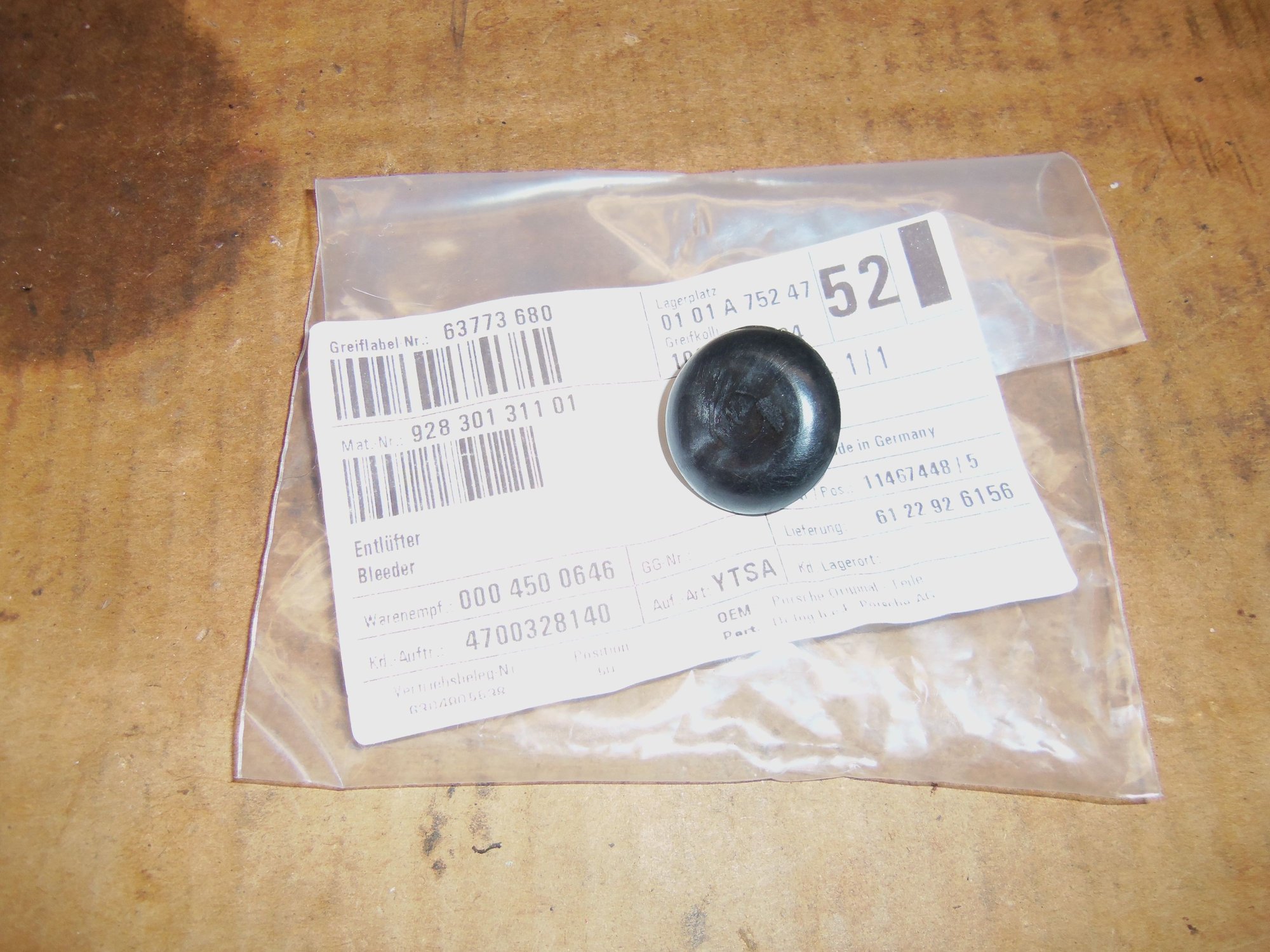
New breather vent and O-ring.
Breather vent bore in top of transmission case.
New breather fitted.
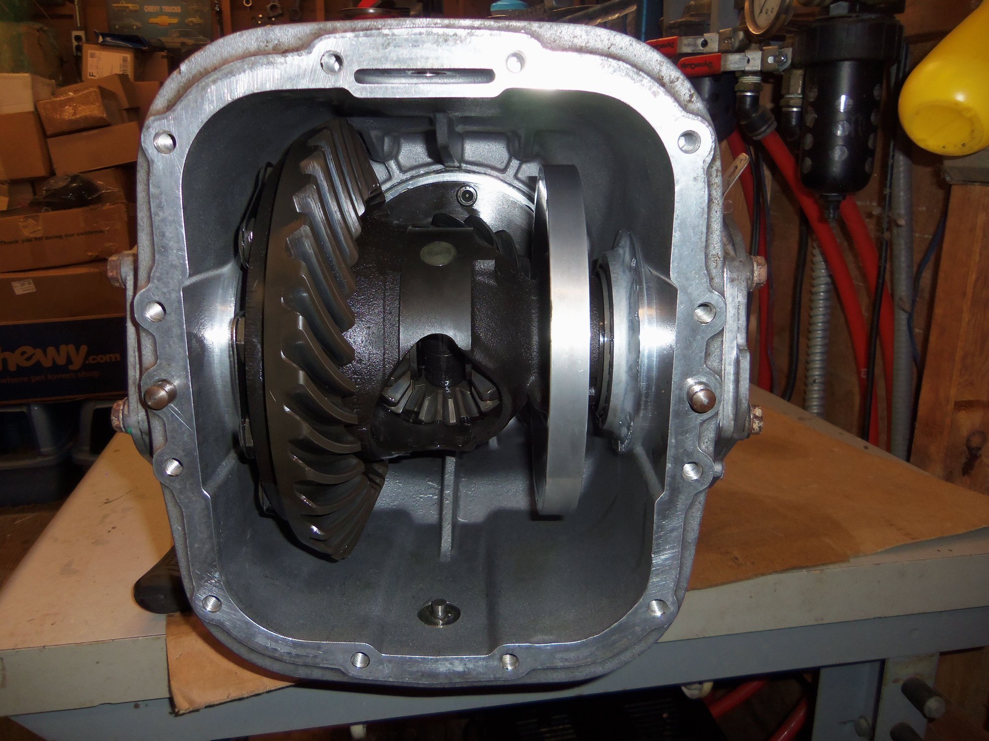
Since I was on a roll, I reassembled the differential.
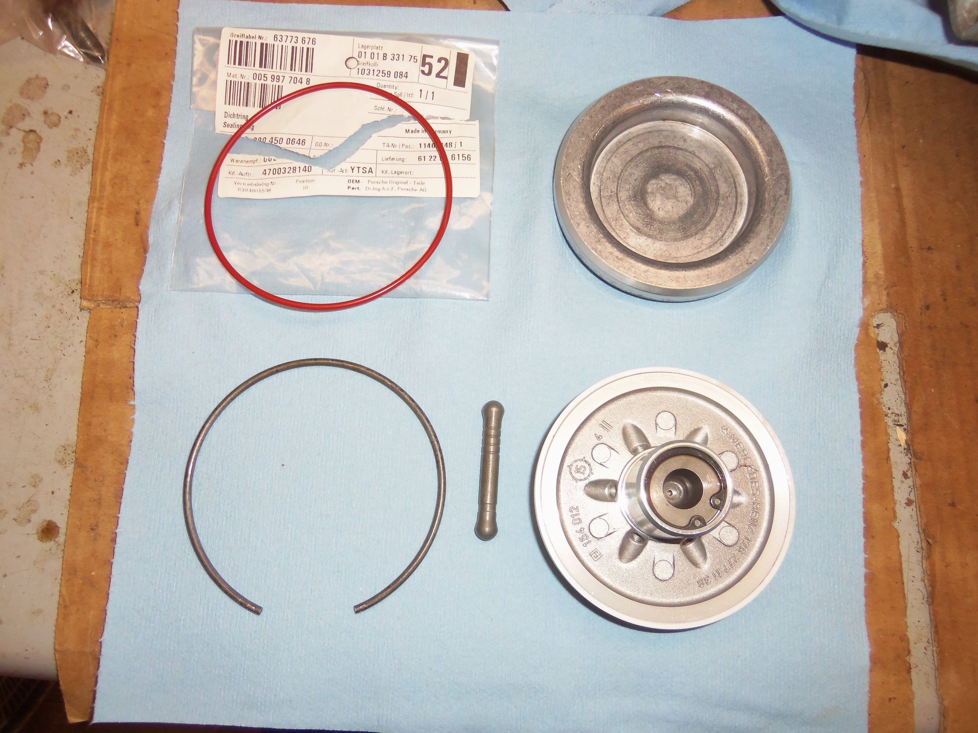
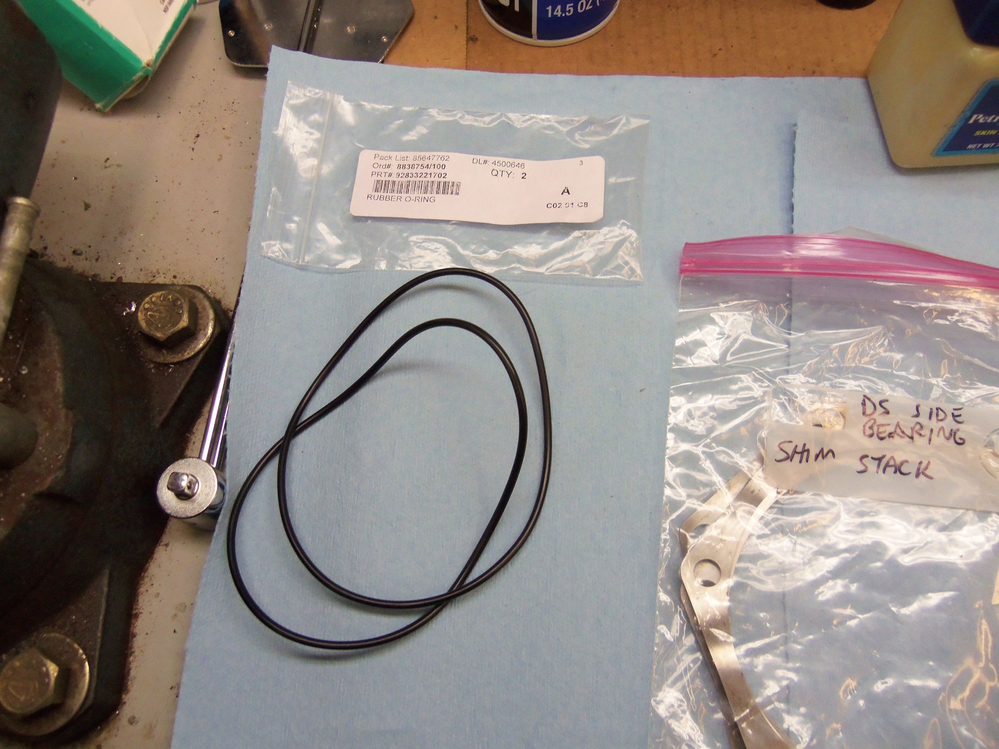
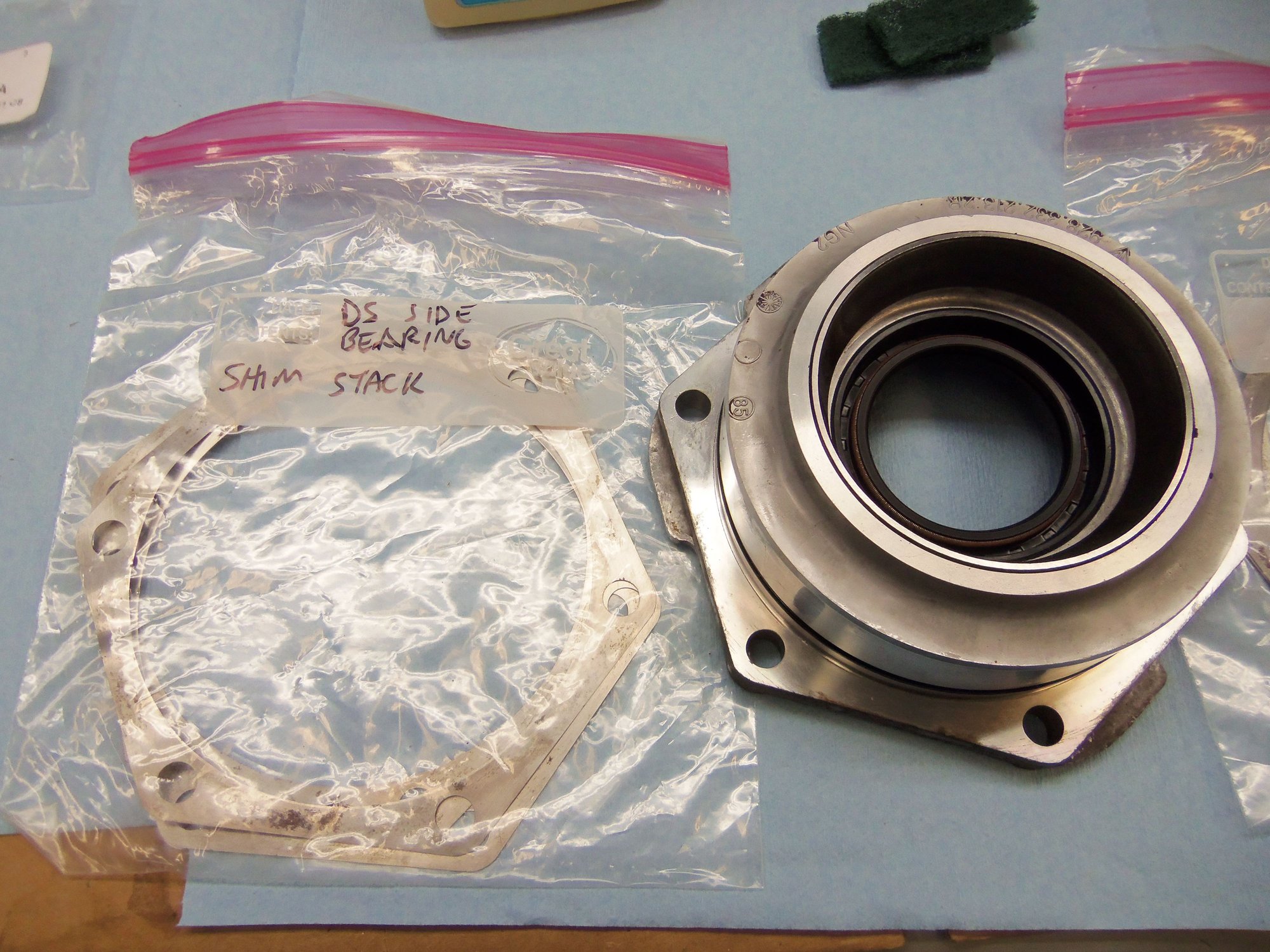
I had replaced the lip seals in the differential carrier bearing side plates in the past, so they just needed to be lubricated with petroleum jelly. I installed new O-ring seals on the side plate 'spigots', lubricated with Dow 111. The sets of shims for the side plates had been cleaned and bagged in the past. I put the sets of shims on their respective side plates. Lastly, I smeared gear oil on the bearing races in the side plates.
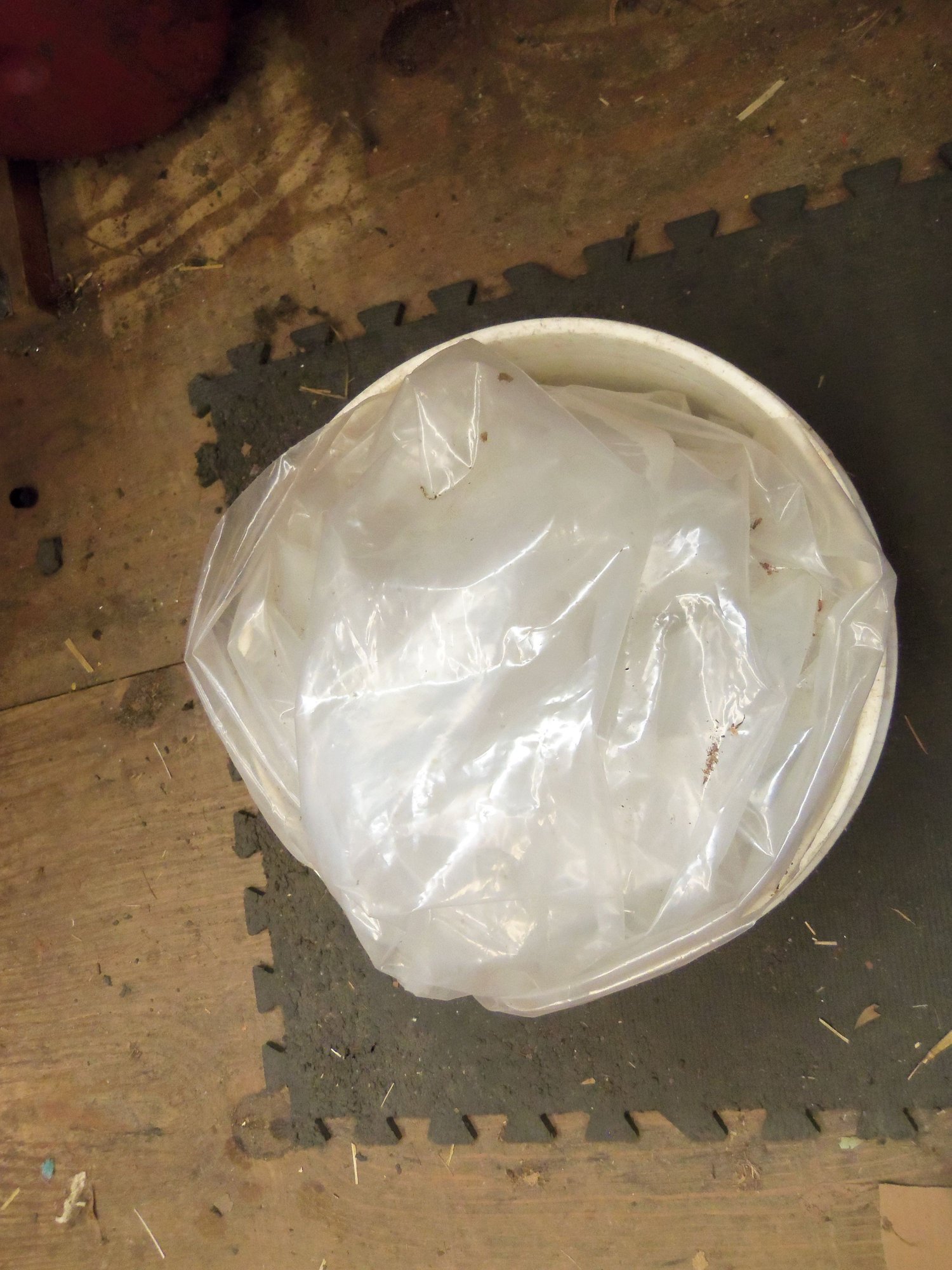
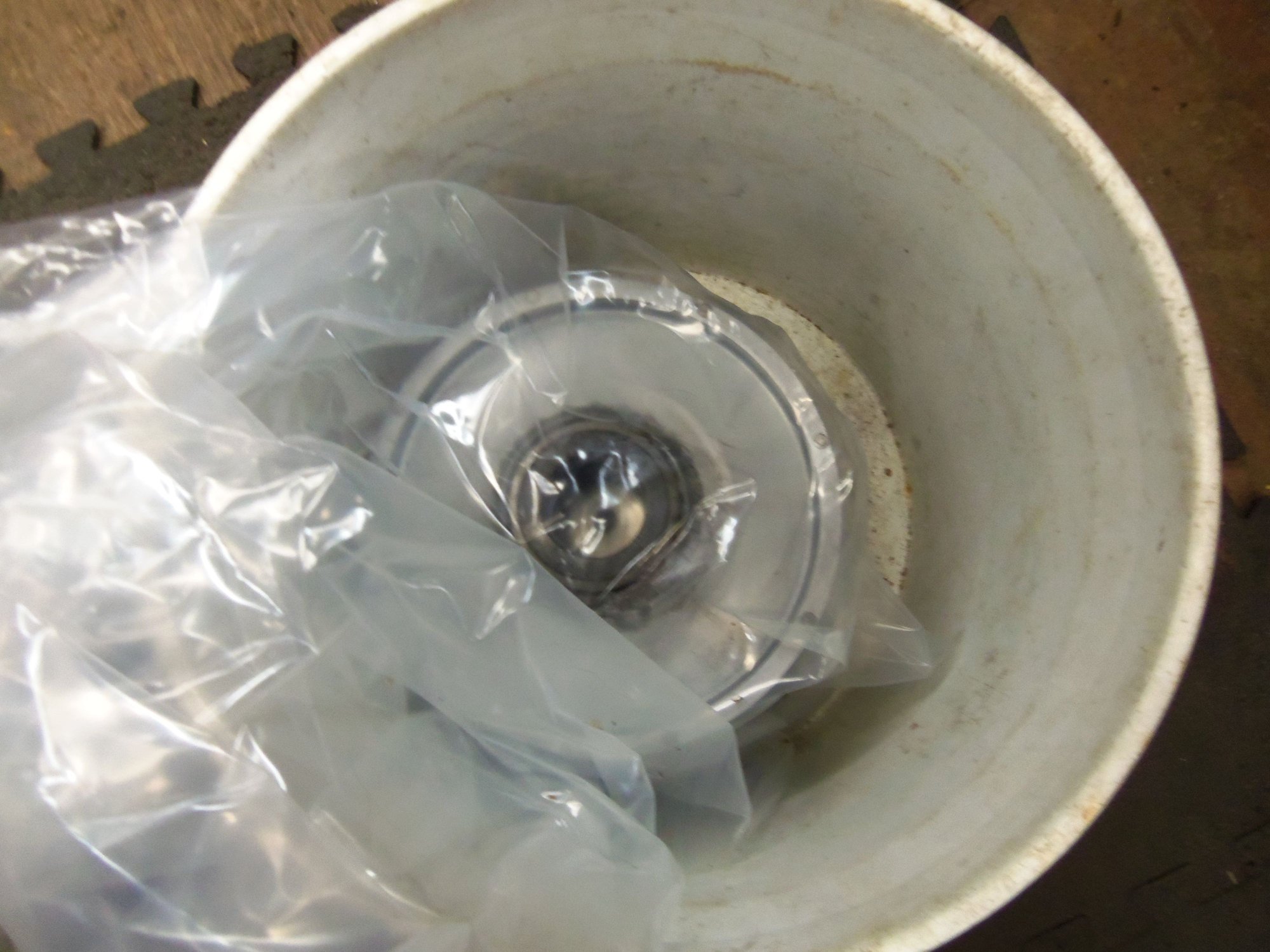
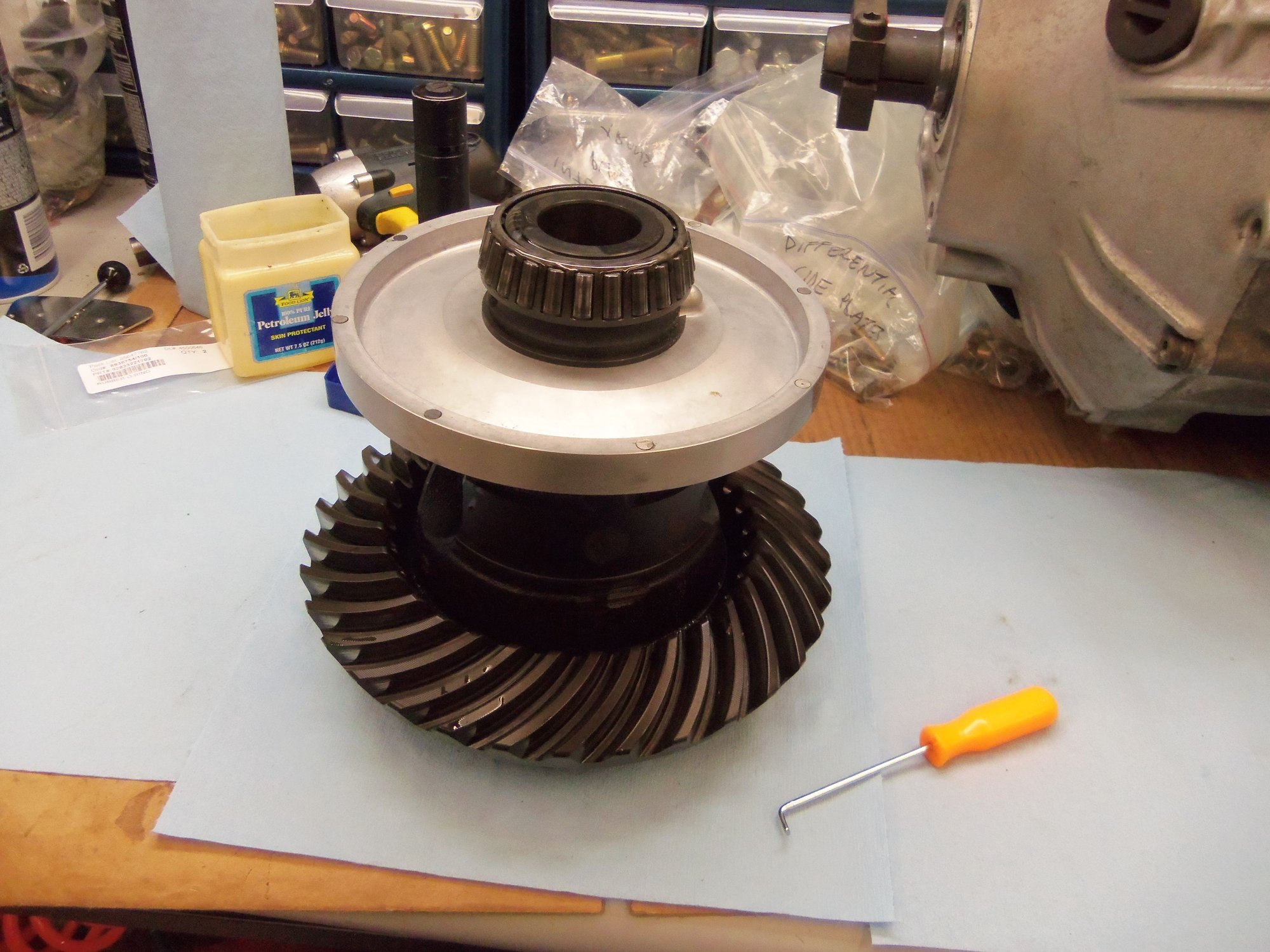
The differential assembly came out of hiding. It had been ensconced in a heavy plastic bag and stashed in a bucket since last year. It was still pristine and oily when I pulled it out now. I poured some fresh Mobil 1 75W-90 LS synthetic gear oil on the side bearings and down into the pinion gears.
Using a small soft faced mallet, I gently pushed the differential casing side plates in until the bearing caps were just starting to protrude from the inside. Then came the juggling act of supporting the differential assembly in place while pushing the side plates all the way in. It was awkward and oily, but I got it. I torqued down the side plate bolts and called it good.
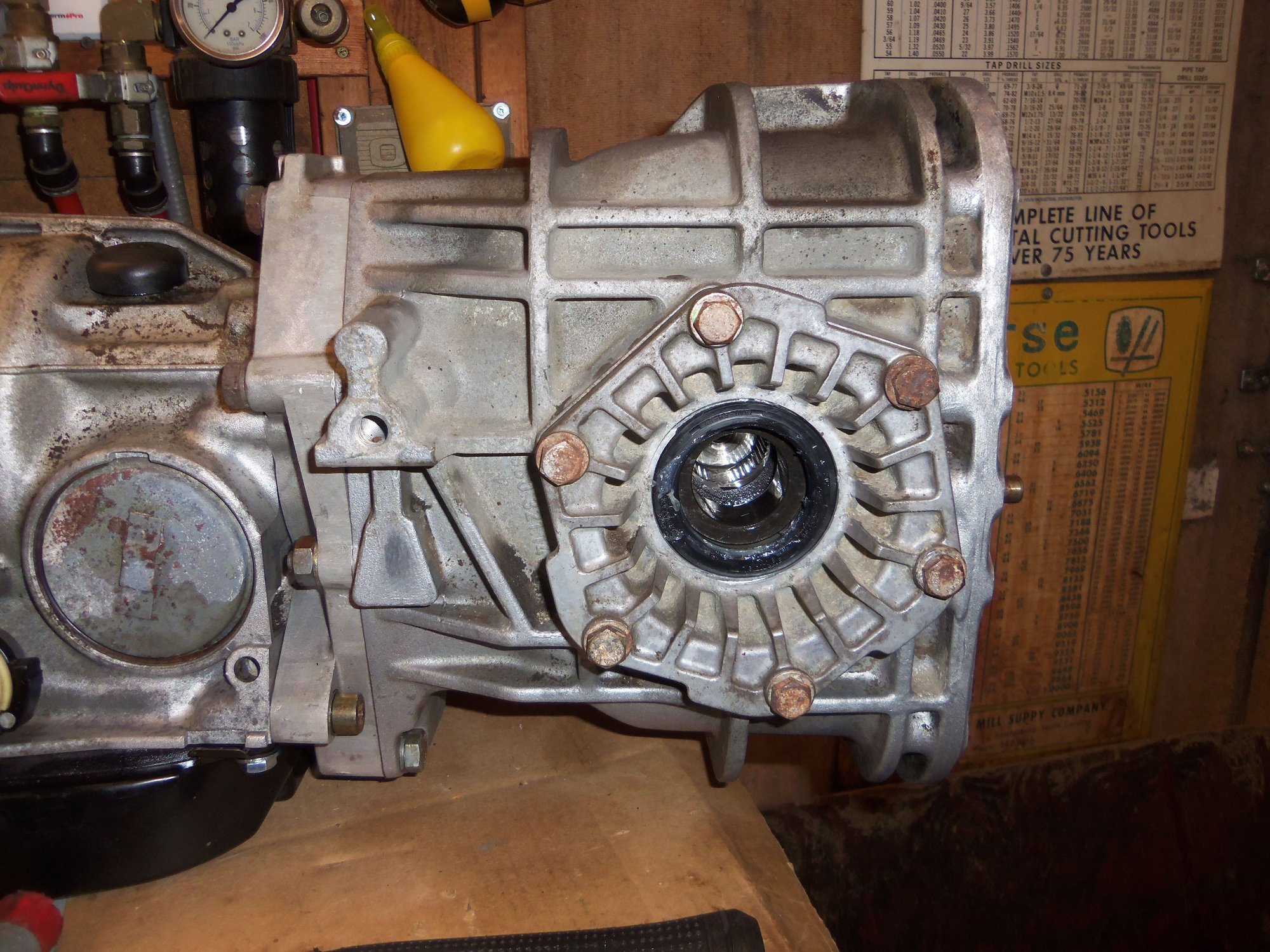
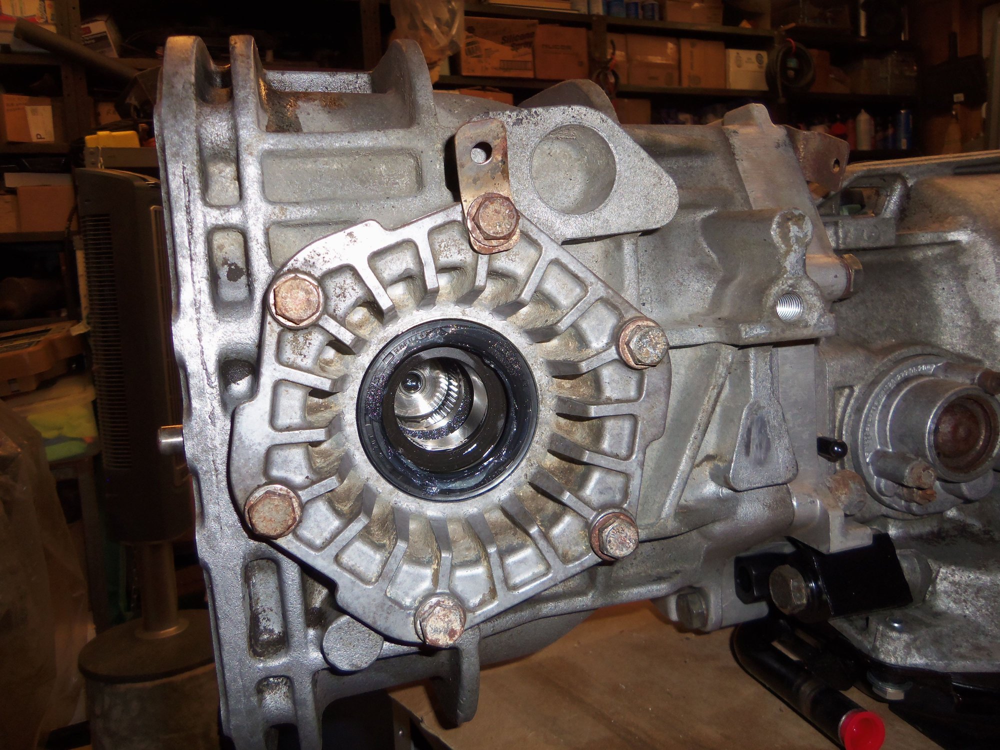
Next came the output flanges. I lubricated the seal surfaces with petroleum jelly and the splines with gear oil on the shafts. Each output shaft pushed right into place with no issues and was torqued down.
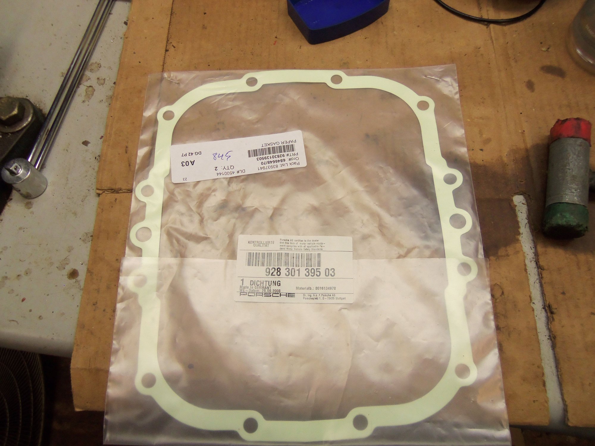
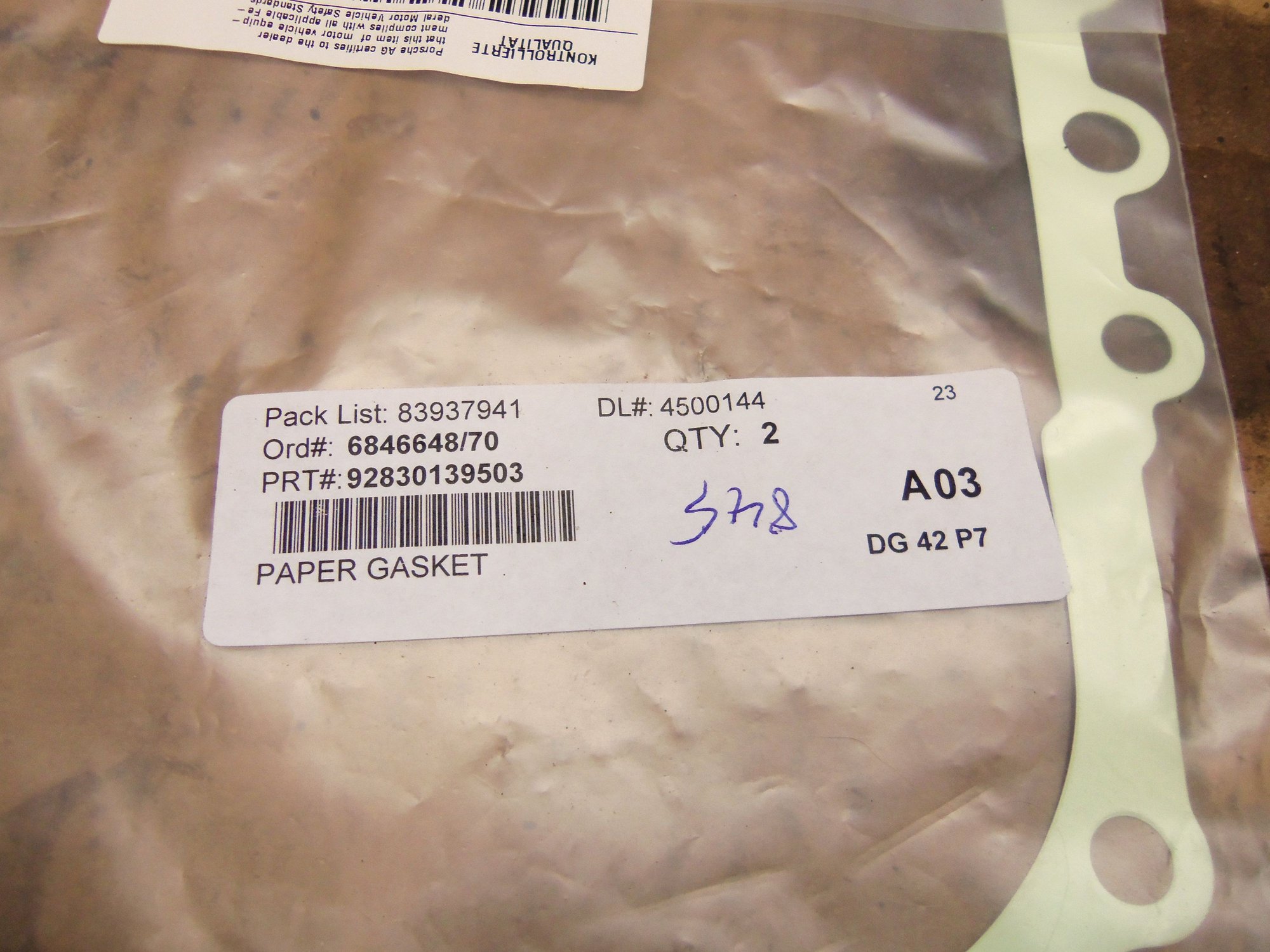
I had to remember where I stashed the new differential cover gasket. It is large and flimsy, so I didn't want it to get hurt in storage. I finally remembered that I put it in a seldom used drawer in one of my tool chests. Gasket was installed dry and the cover torqued down.
I installed the magnetic drain plug with a new aluminum crush washer lightly coated in PTFE pipe dope into the bottom of the differential casing. Since I had much better access on the workbench than under the car, I went ahead and filled the differential. It took 101 oz of Mobil 1 75W-90 LS synthetic gear oil to fill it to the fill port. Fill plug went in with a similarly prepared crush washer.
Note: WSM Volume 3, Section 30, page 0103 lists rear axle final drive oil capacity as approximately 2.7L for up to 1986 MY. 1987 - 1990 MY is listed as approximately 30.L. 101 oz is approximately 3.0L. Hmmm...I did notice the differential casing on my transmission has a cast in mount for the later PSD actuator...
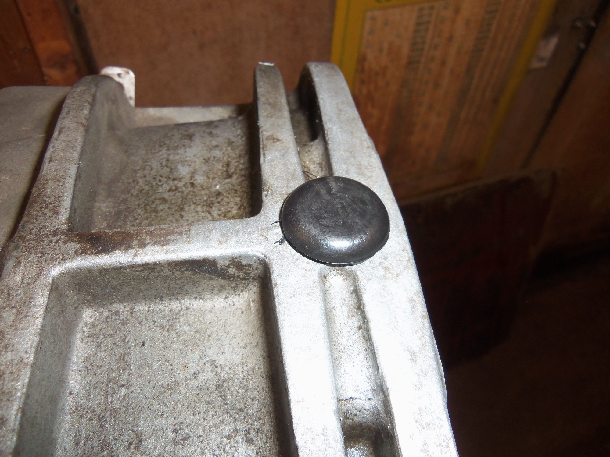
Anyway, next was fitting a new differential case breather. That little bugger was a tight fit!
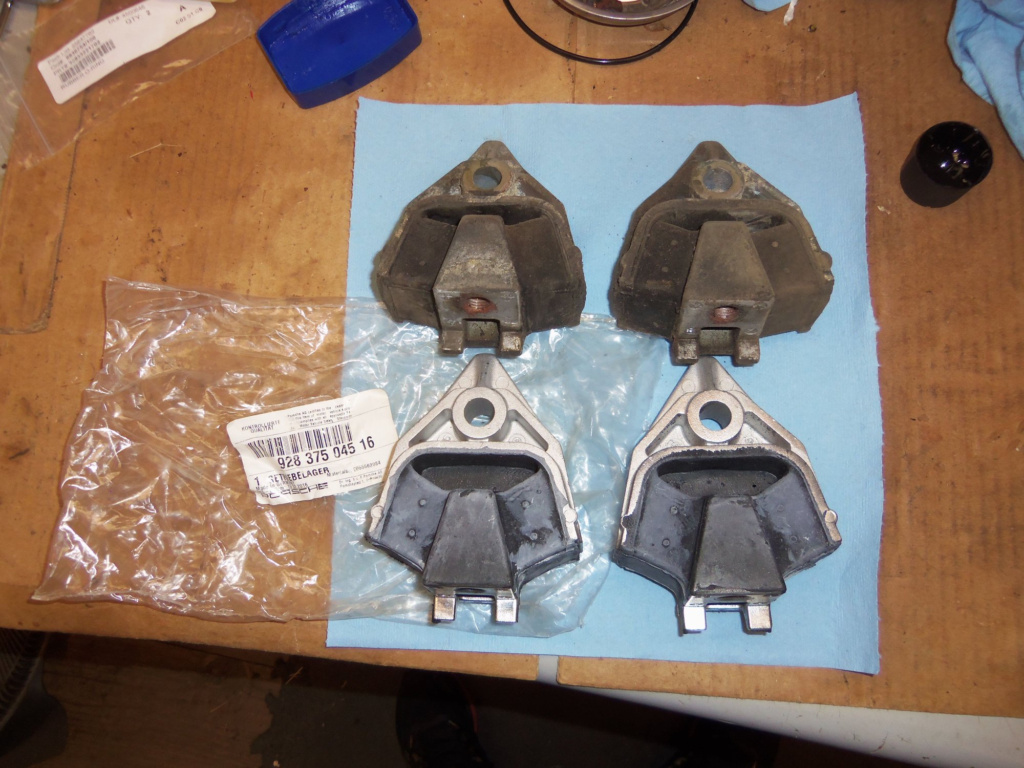
Next came the new transmission mounts. I held up on the mounts to take up any slack as I bolted them to the differential casing.
Last step was to fit and route the transmission wiring harness.
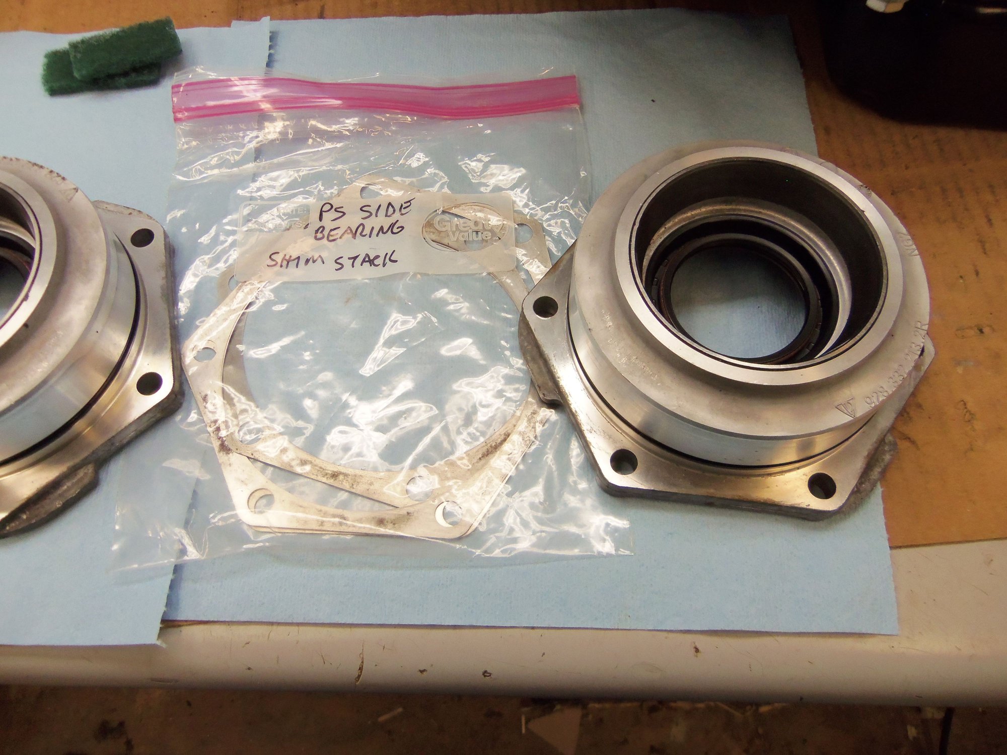
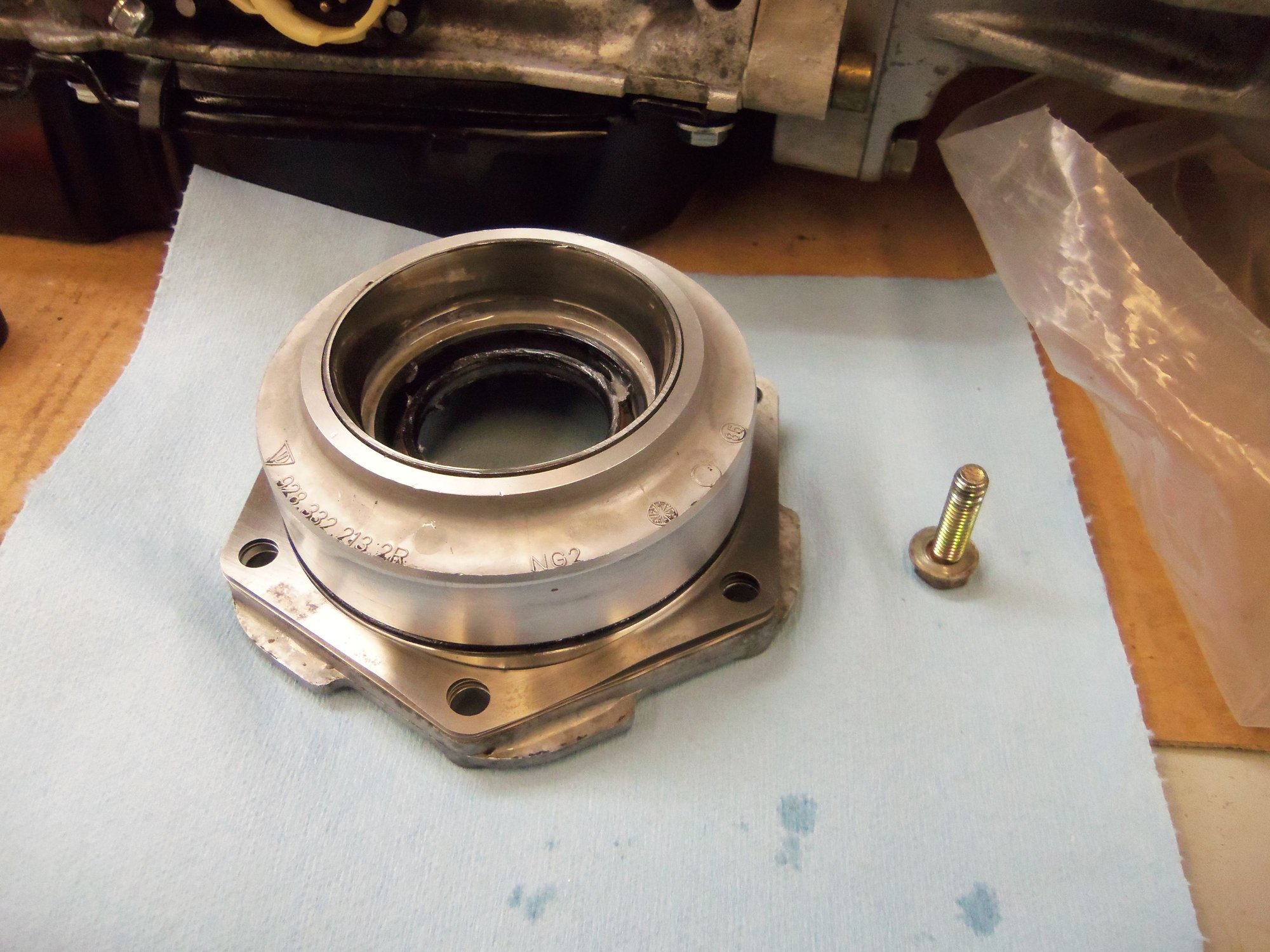
New O-ring seals for the 'spigots' on the differential bearing cap side plates.
Driver's side plate and shim stack.
Passenger's side plate and shim stack.
Driver's side plate lubricated and ready to install, with one mounting bolt to hold it.
Parts laid out for installation.
Differential's hiding place for over a year.
There it is! Finally seeing the light of day.
Still pristine.
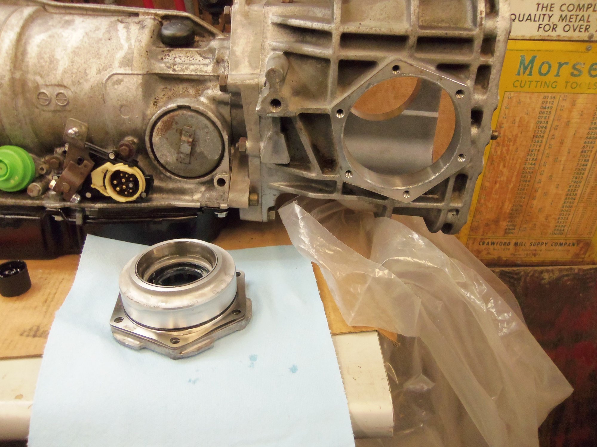
Driver's side plate installed and torqued down.
Passenger's side plate installed and torqued down. Note I remembered to install the mounting tab for the wiring harness.
Differential assembly back where it belongs.
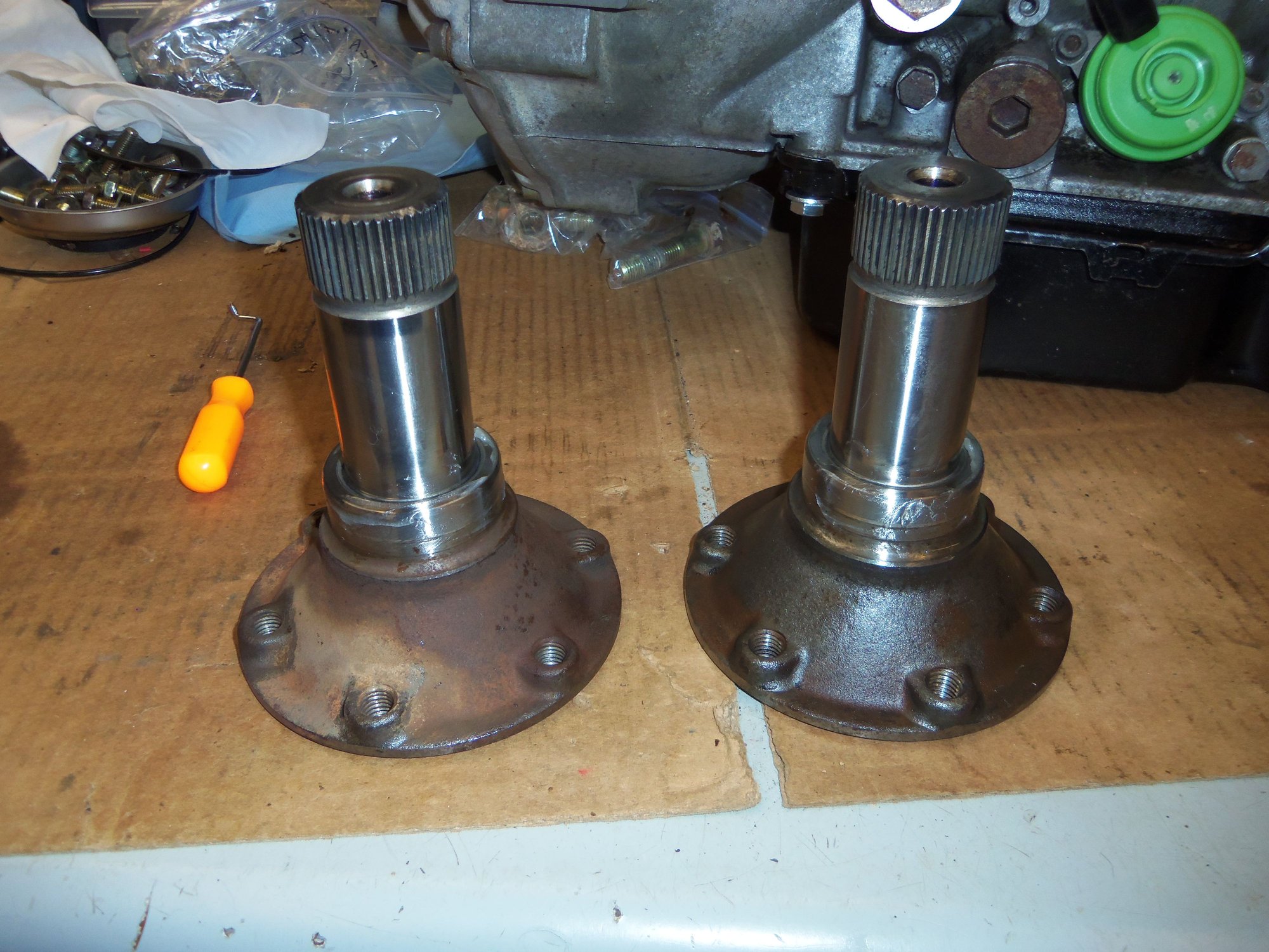
Driver and passenger's side output flanges.
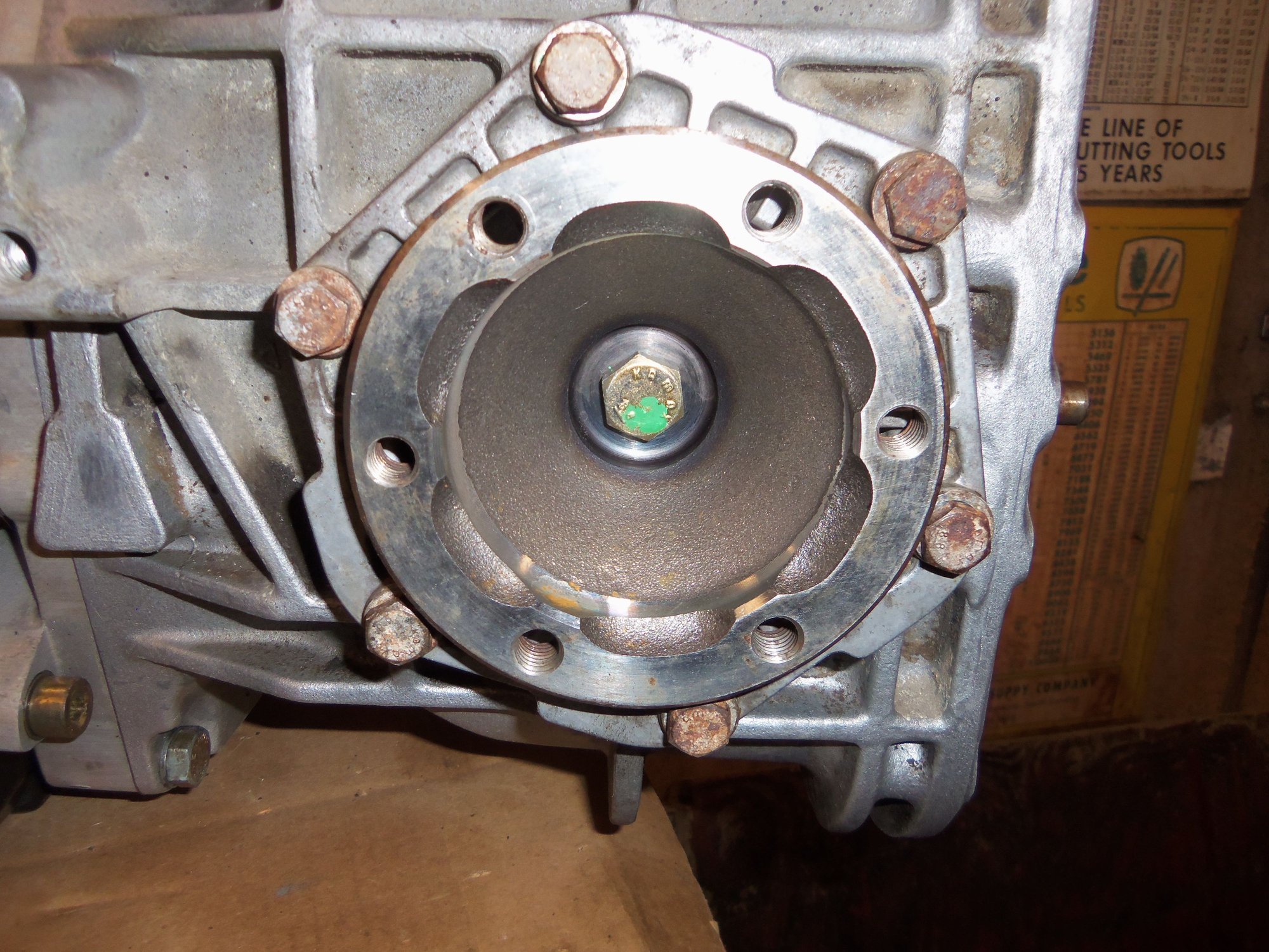
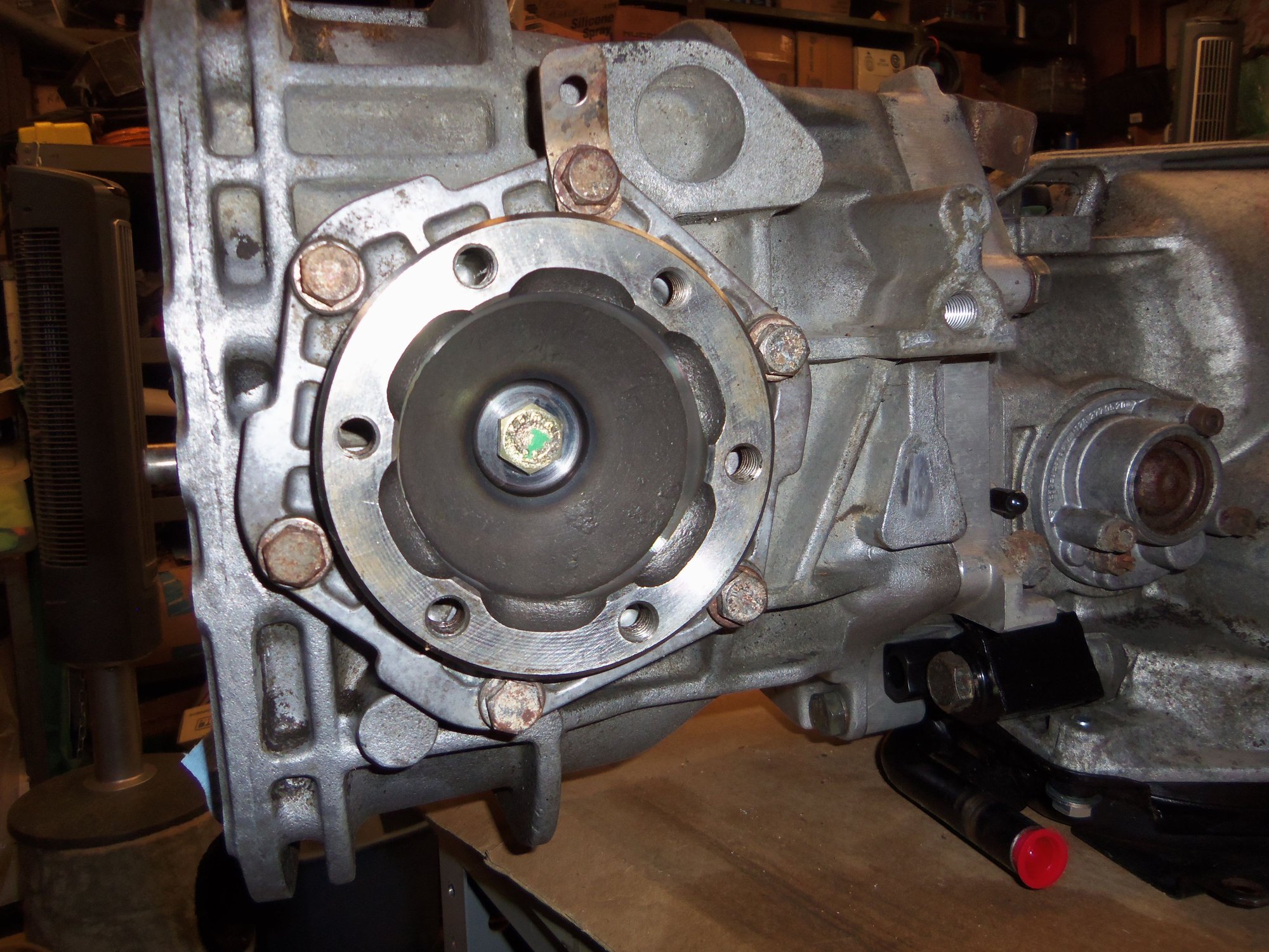
Driver's side output flange installed.
Passenger's side output flange installed.
New differential cover gasket. After I remembered where I had put it...
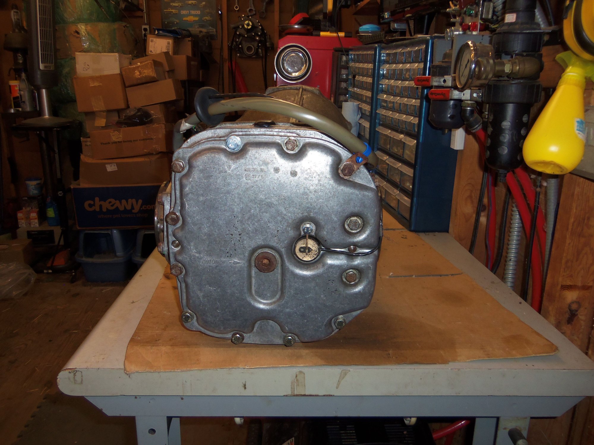
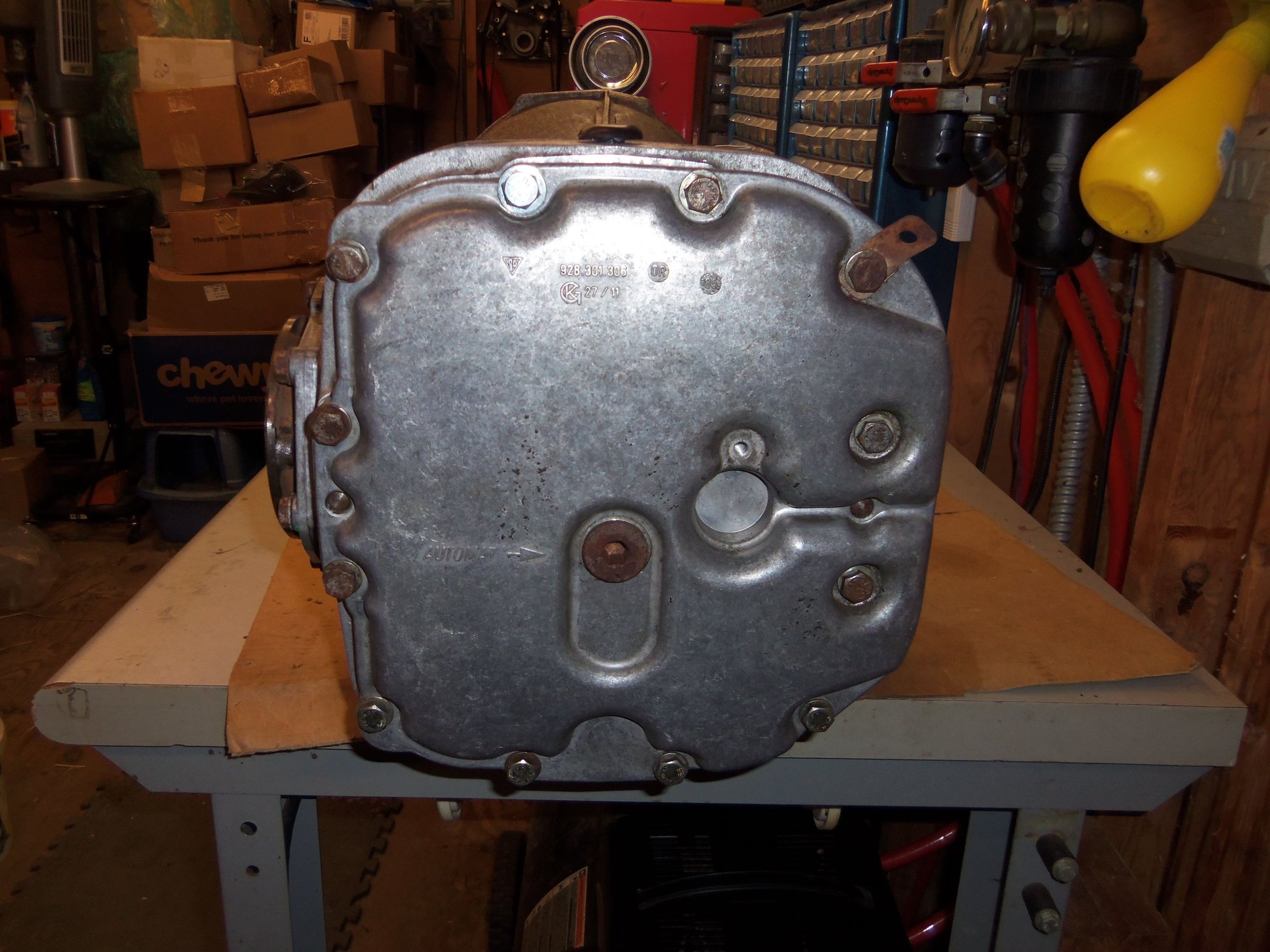
Differential cover installed and torqued down. Fill plug is temporarily installed.
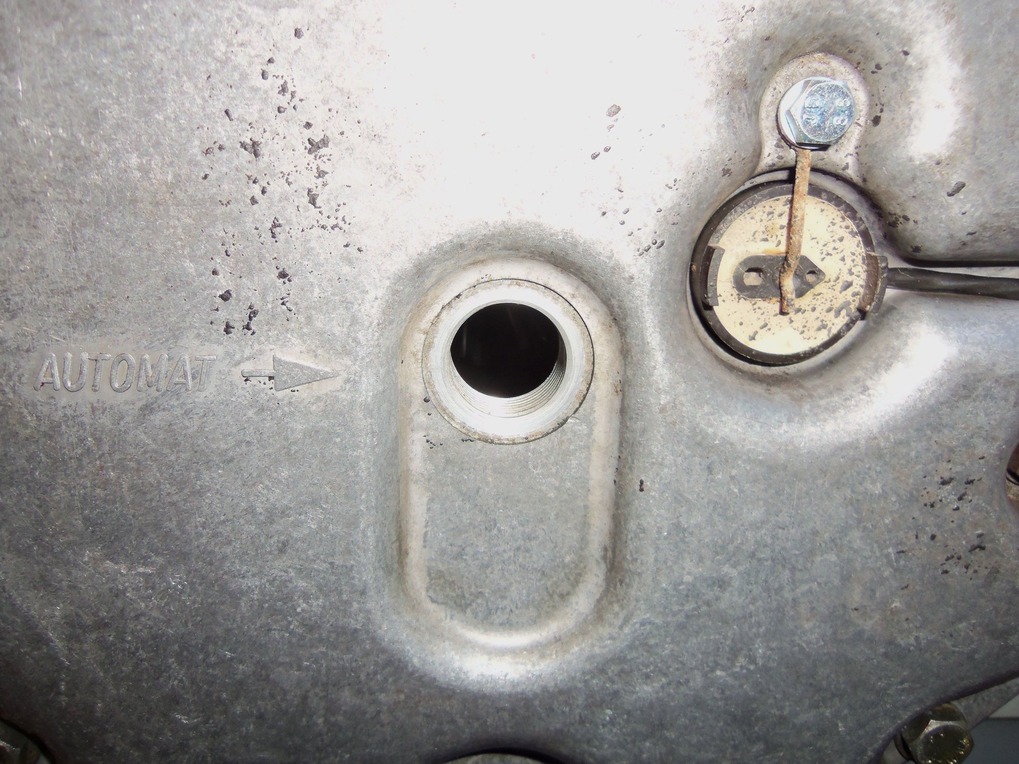
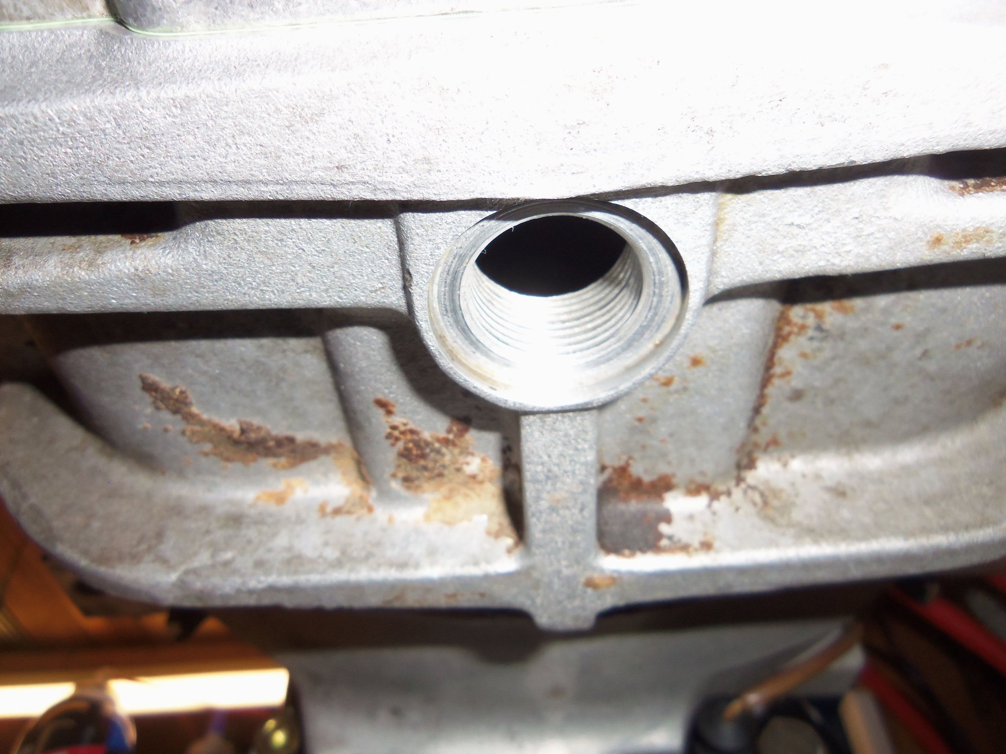
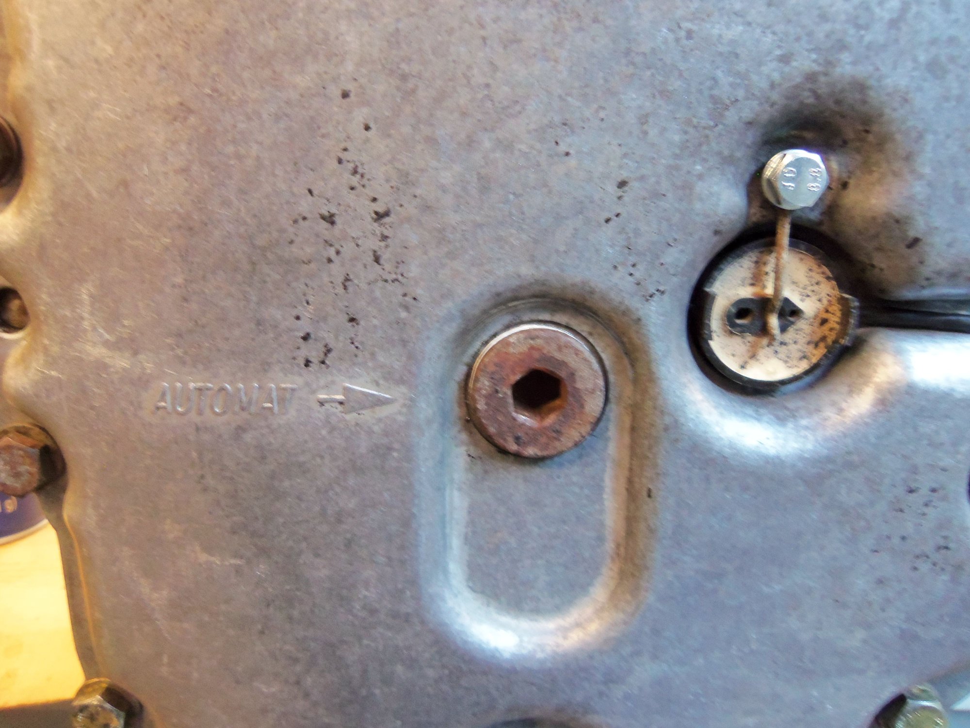
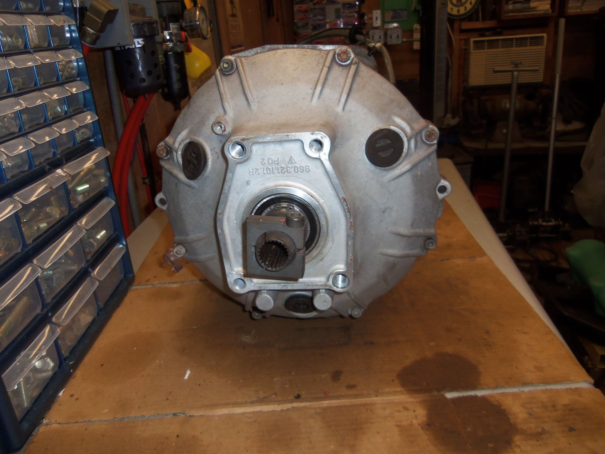
Fill plug hole. Note 'AUTOMAT' only cast in marking.
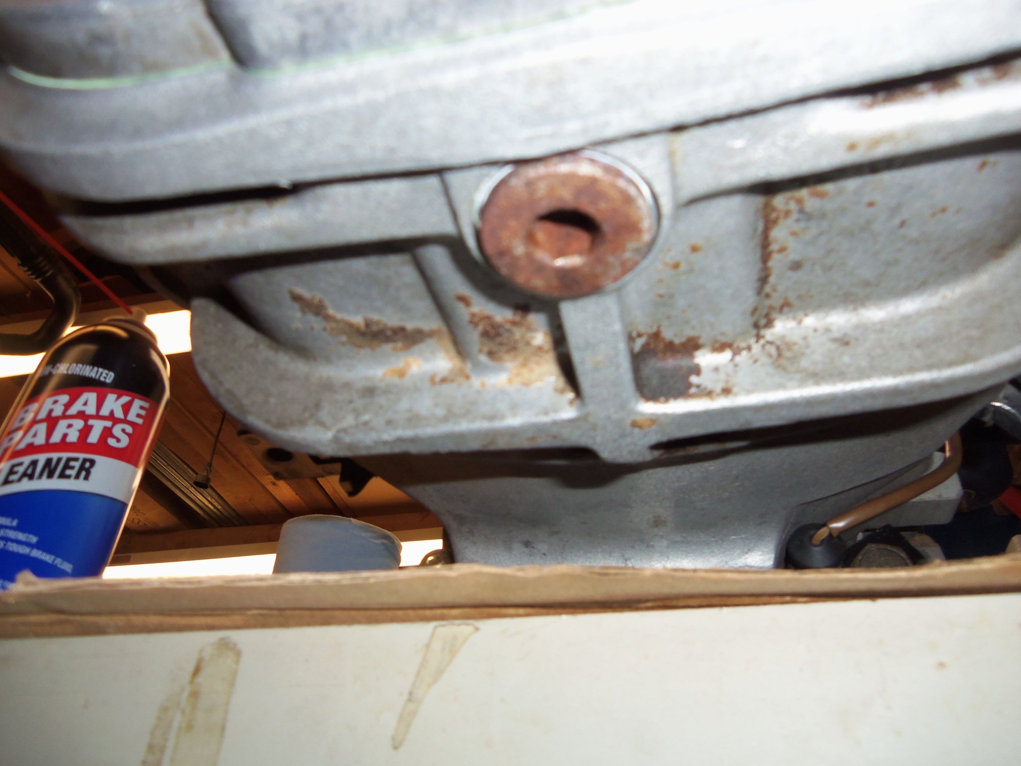
S4 style drain hole at the bottom of the differential. Because the routing of the exhaust blocks access to the traditional drain hole at the bottom of the differential cover.
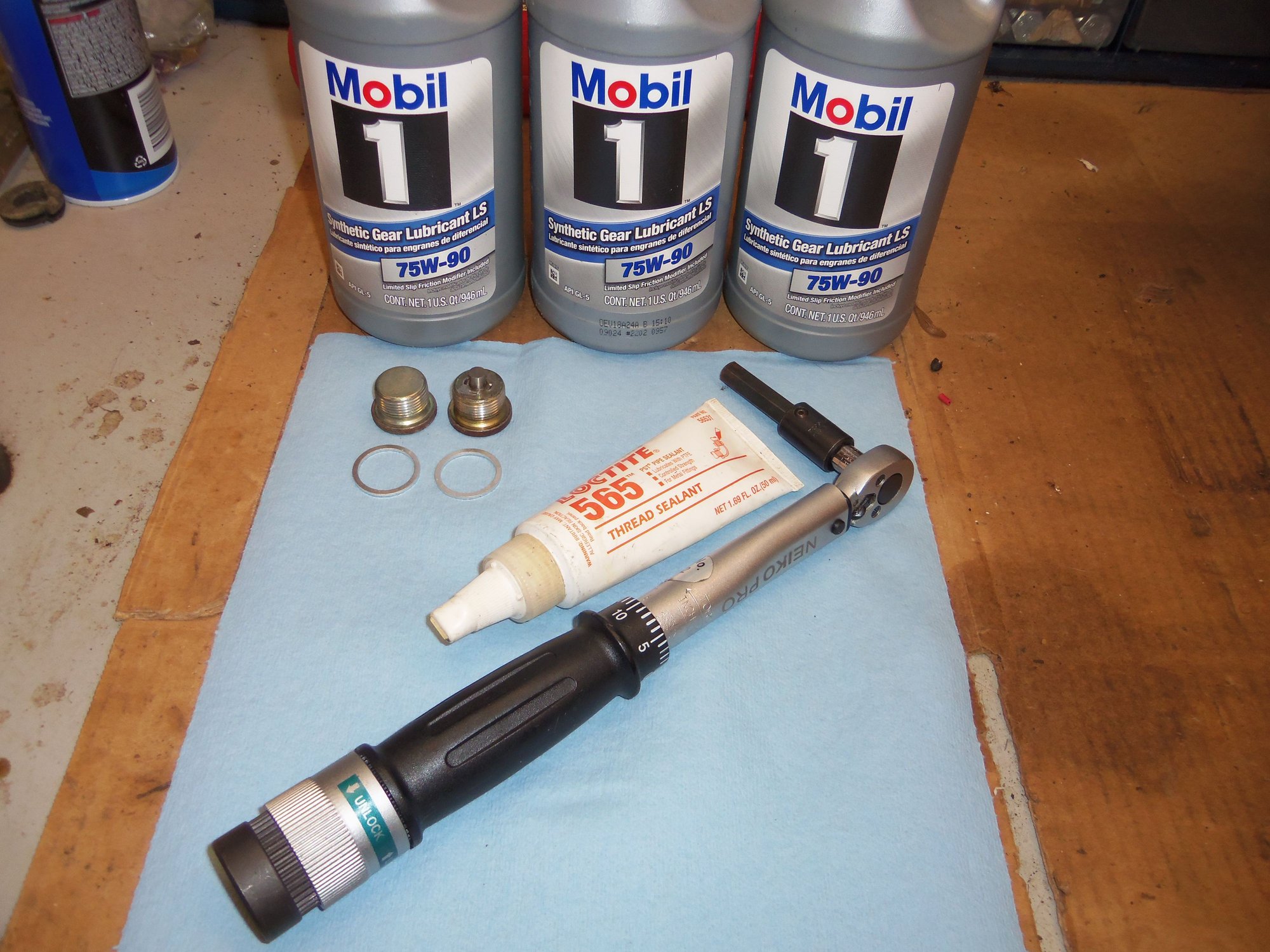
Gear oil, fill & drain plugs, new crush rings, PTFE sealant, and the all important torque wrench.
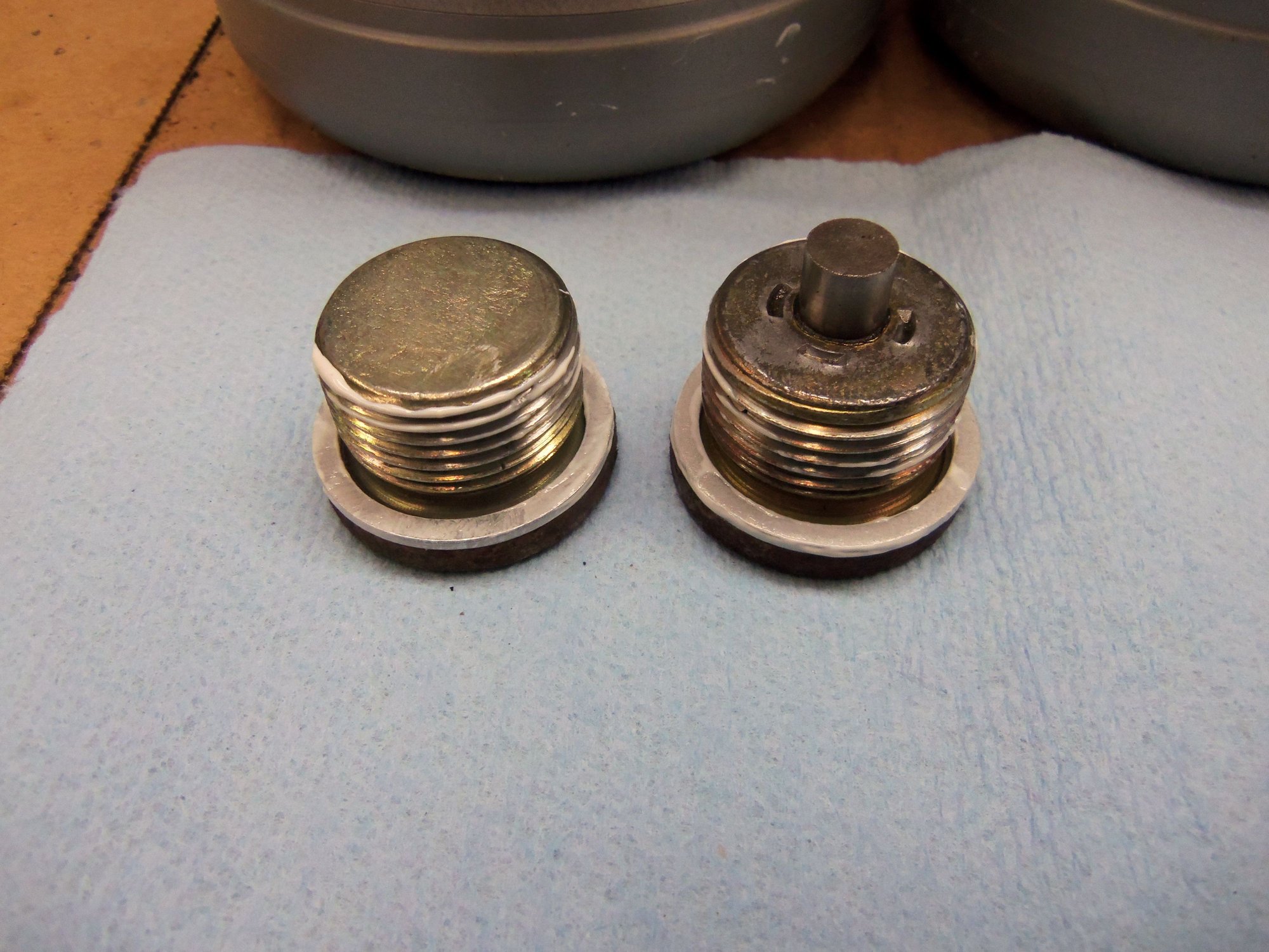
Coated crush rings on the plugs. Drain plug has the magnetic element.
Drain plug fitted first.
Fill plug fitted after adding gear oil.
New differential casing vent.
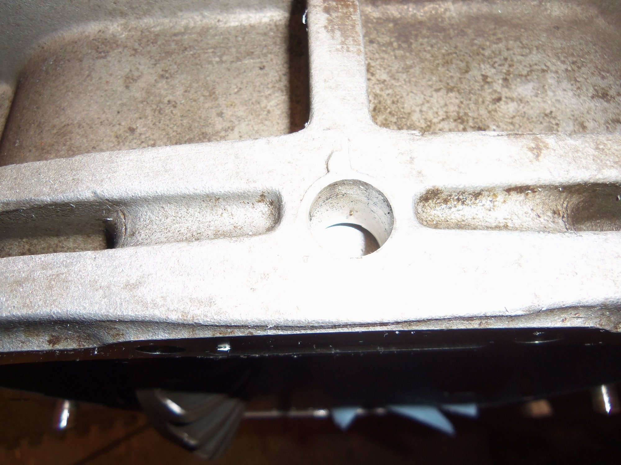
Differential casing vent bore.
Vent installed.
Old worn out transmission mounts at the top and new mounts at the bottom.
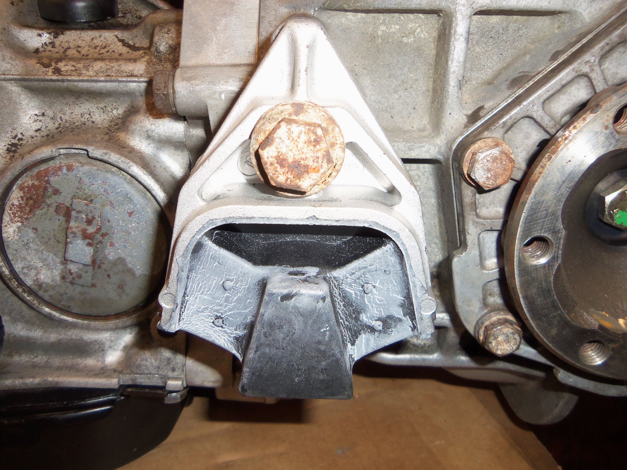
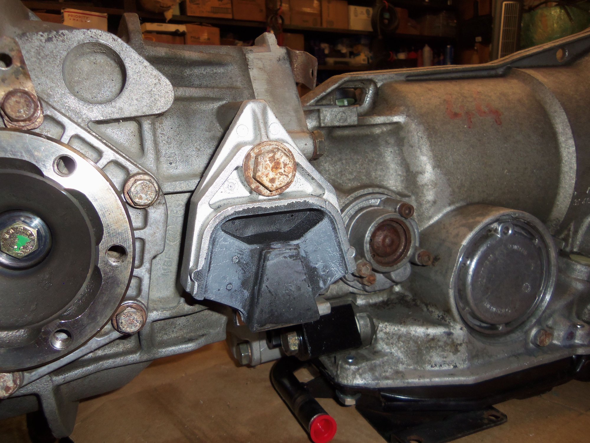
Driver's side transmission mount installed.
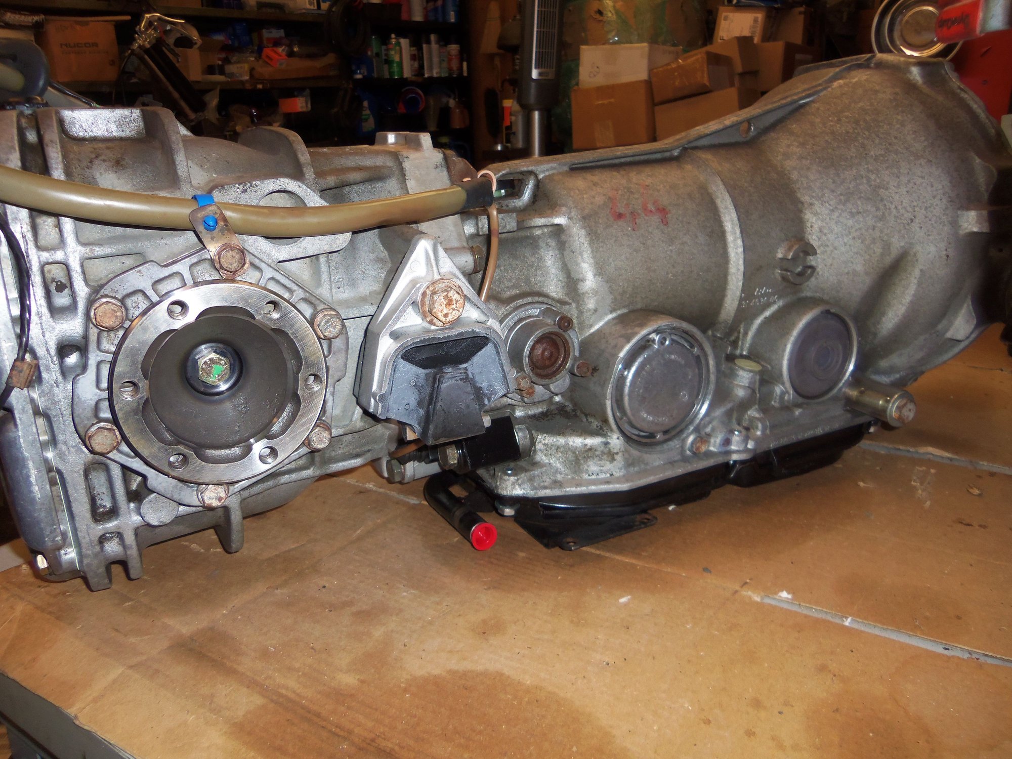
Passenger's side transmission mount installed. Note cast in mounting point for later PSD actuator...
And it was done. After way too long of having all this apart, I again have a complete transmission assembly. Game plan is to run it for 1000 miles, then change the ATF and differential gear oil just because. Fit a new transmission filter and pan gasket, and be good for awhile.
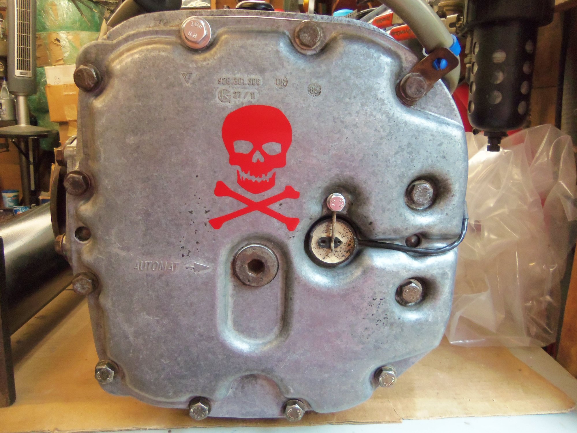
Oh, I added a little signature to the differential cover. ALL of my vehicles have a skull and crossbones on the differential cover. Even my old John Deere 317 garden tractor.
What a great "how to" for us DIYers! Thanks for the exceptional photo documentary Seth, this is epic!
I don't relish the idea now, but when I move into my new shop I think I'll follow in your footsteps and rebuild my spare using these instructions. Really awesome job and a real credit to you. Good luck on the TT rebuild. I did mine on the 944 using Constantine's bearings and it came out great.
Best Regards,
Thank you, Otto! I appreciate the praise. However, remember, this was NOT a rebuild. Just a reseal. Having said that, I am glad my photos and documentation are helpful!
Torque tube is done, and was harder in some respects than I expected.
I started off by reviewing threads by Sharkskin and Dwayne on torque tube rebuilding. As well, I had all the documentation from Constantine for installing the SuperBearings.
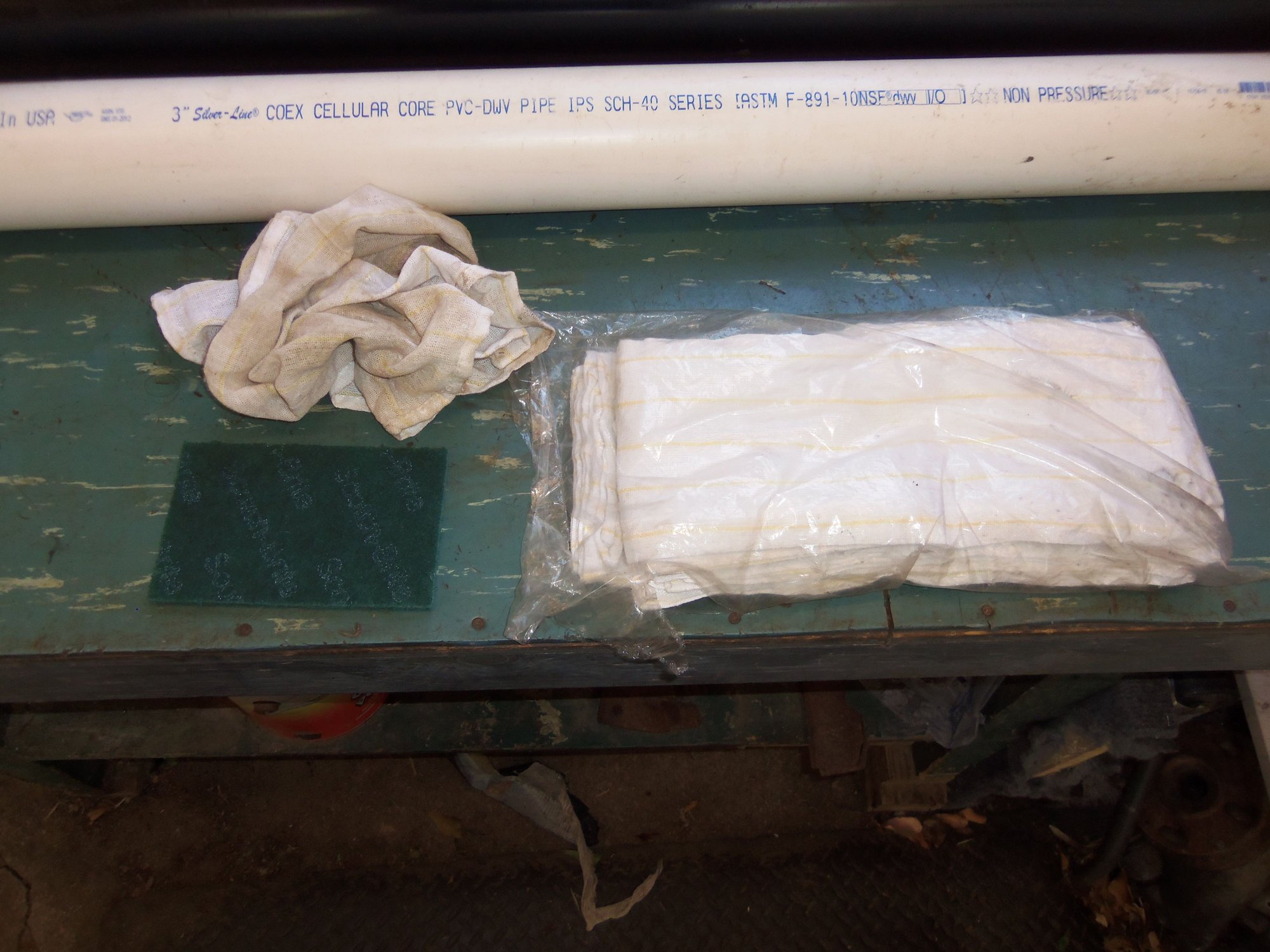
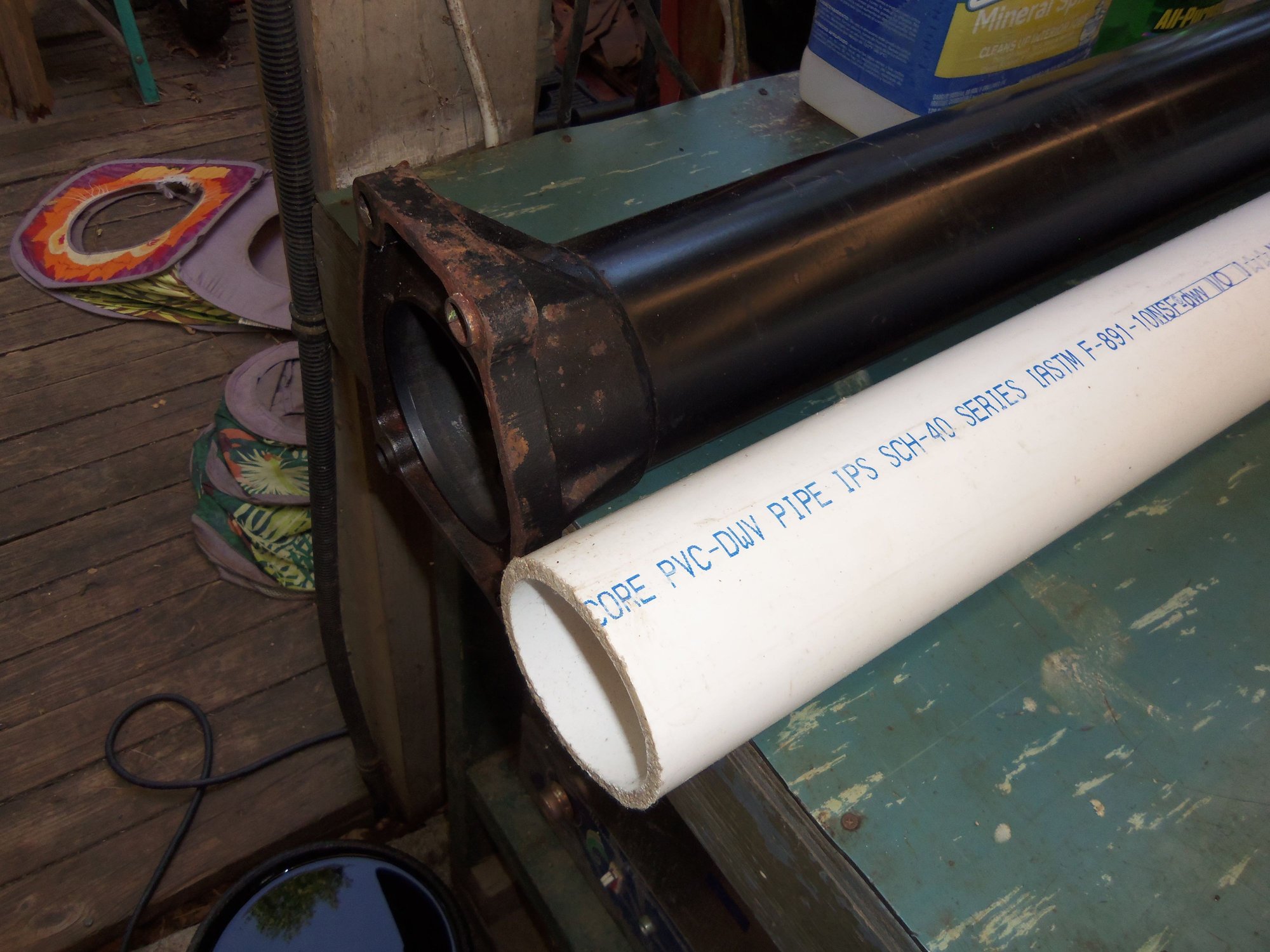
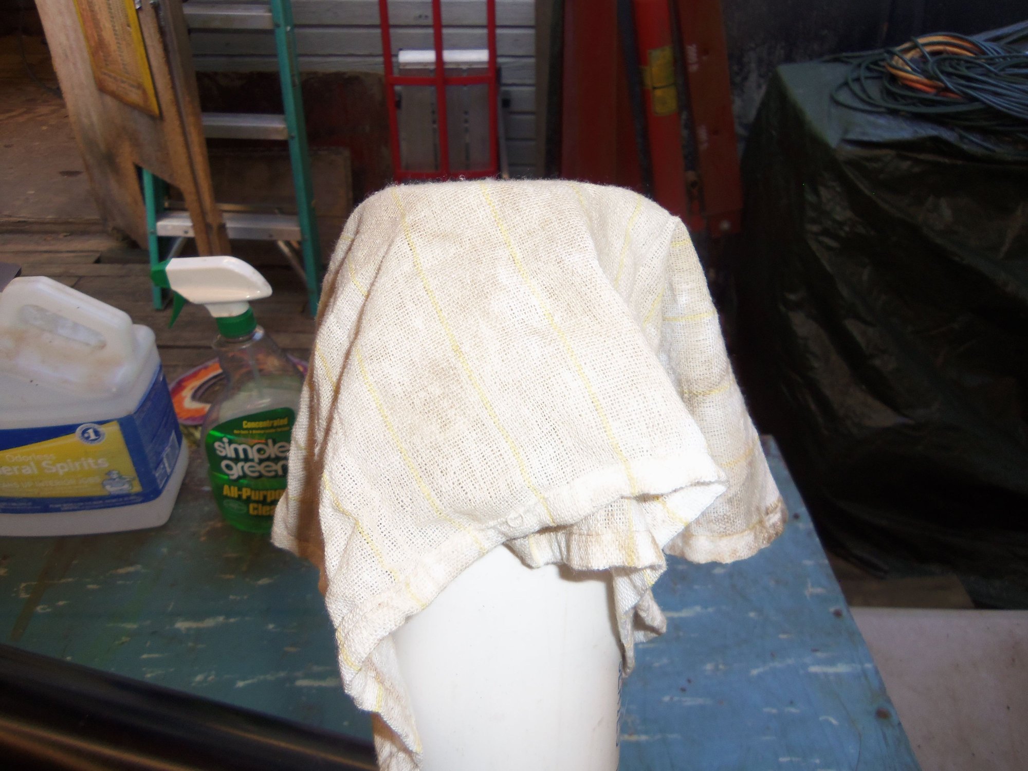
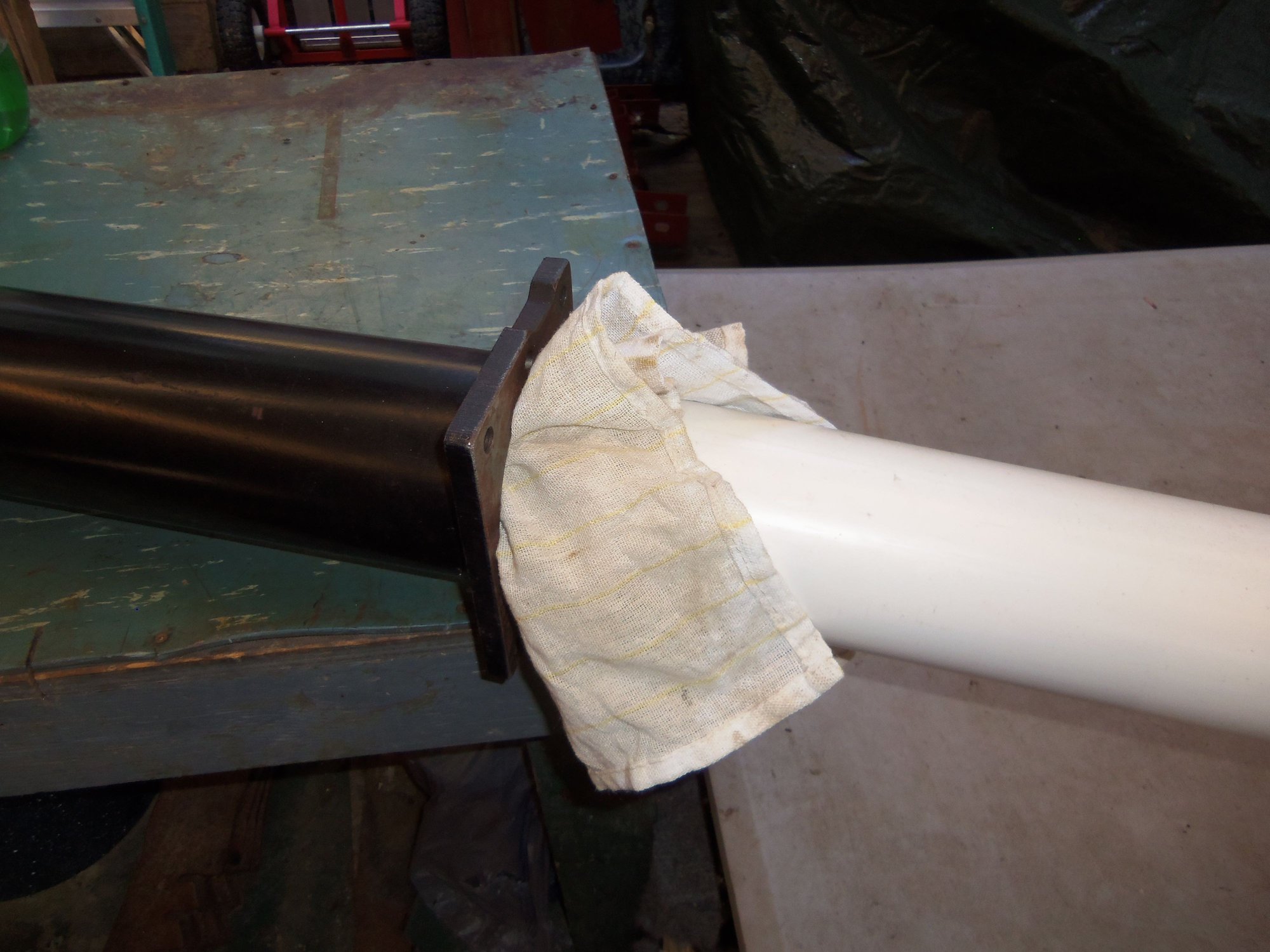
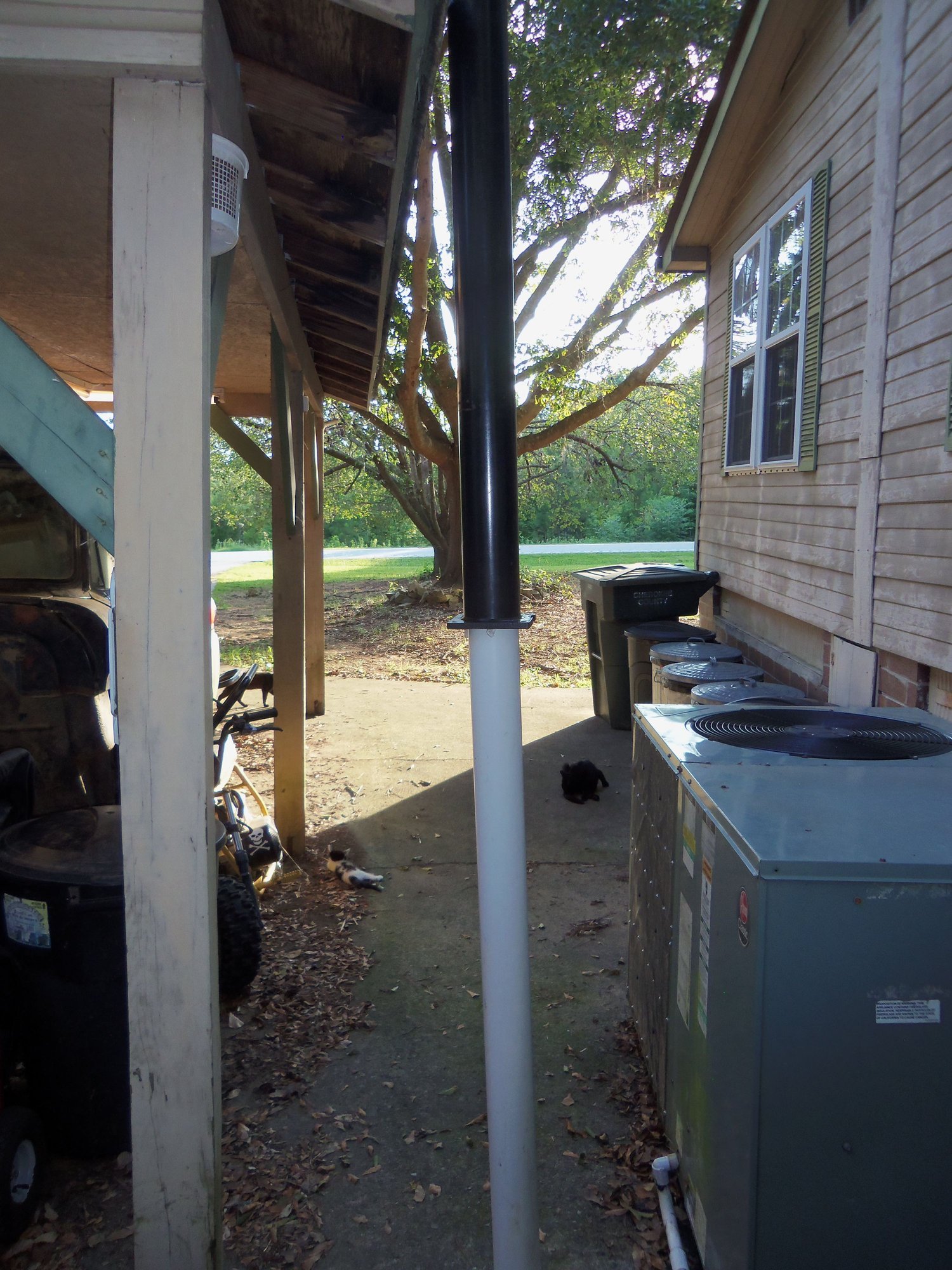
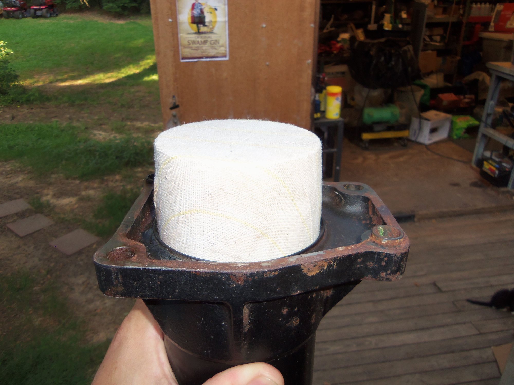
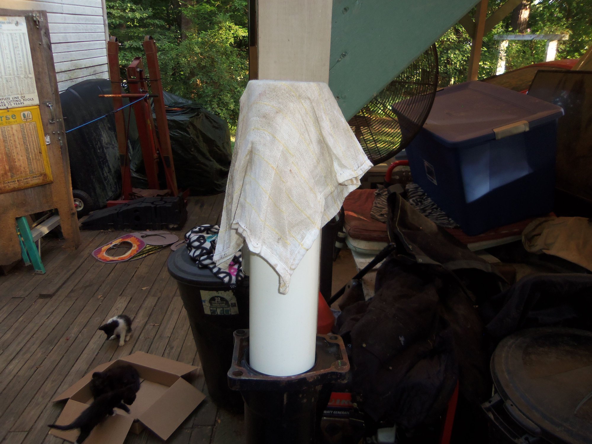
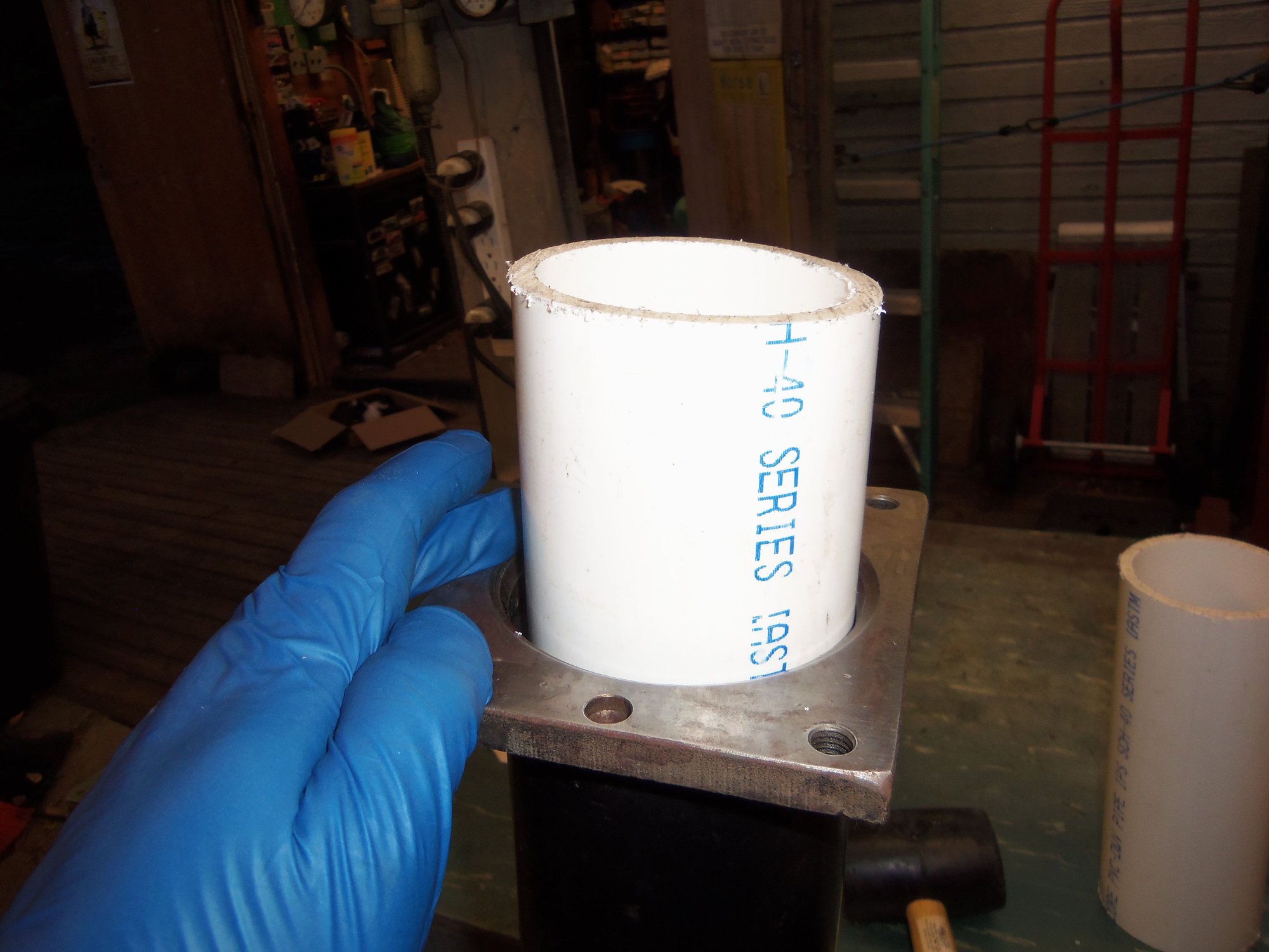
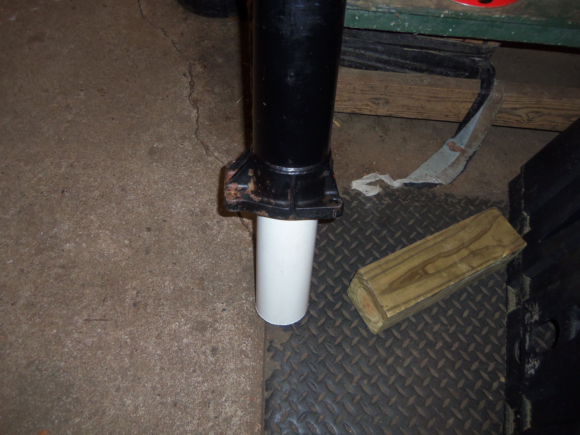
I cleaned the torque tube itself inside and out with Simple Green cut to 30% and rags. Elbow grease and scrubbing took care of the outside and flanges. For the interior, I sprayed cleaner into the tube, soaked a rag in cleaner, then put the rag over a length of 3" OD PVC tubing. The tubing was longer than the torque tube. I pushed the rag into the torque tube as far as it would go with the PVC. Which was not very far. So, I turned the whole thing up vertically with the PVC tubing down. Firmly holding the torque tube, I bumped the PVC on the concrete over and over. Think using a fence post driver for the motions. This pushed the rag and PVC through the torque tube. I did this procedure several times, changing directions each time. It was tiring (bare torque tube is surprisingly heavy), but it worked well.
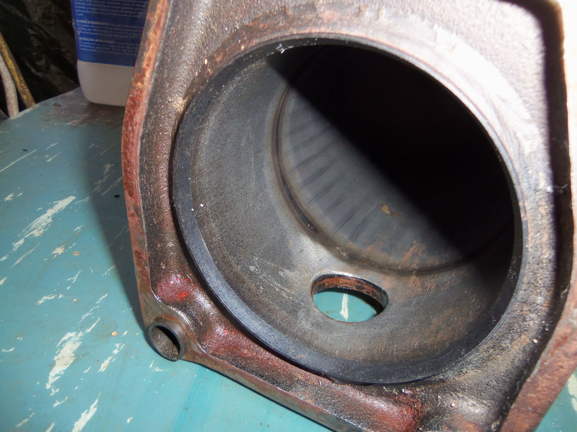
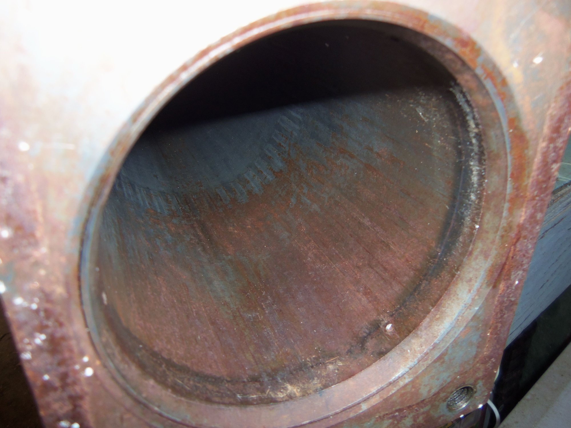
I went back with a green Scotchbrite pad and some mineral spirits to scrub at some surface rust in the ends of the tube. That was moderately successful. I hit the ends of the flanges on the tube with a wire brush to clean off the rust.
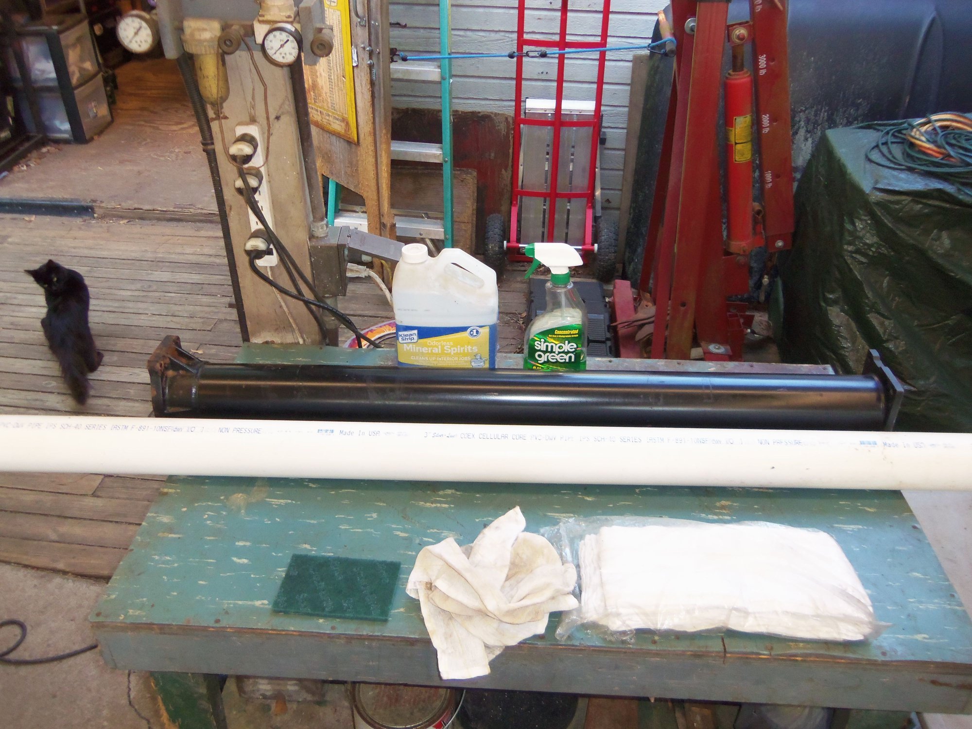
Torque tube scrubbing for dummies. Like me.
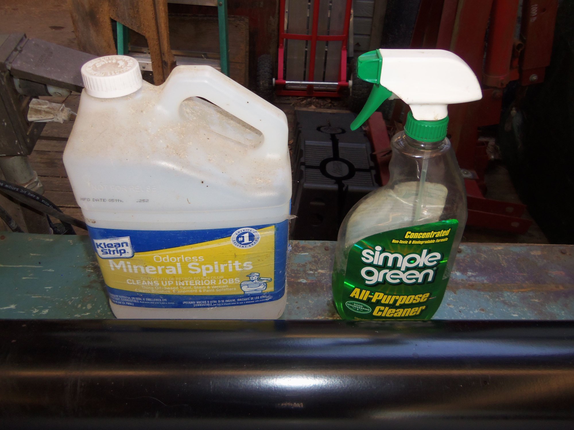
Cleaners. Nothing exotic. Simple Green is cut to 30% with tap water.
Lint free coarse rags and a green Scotchbrite pad.
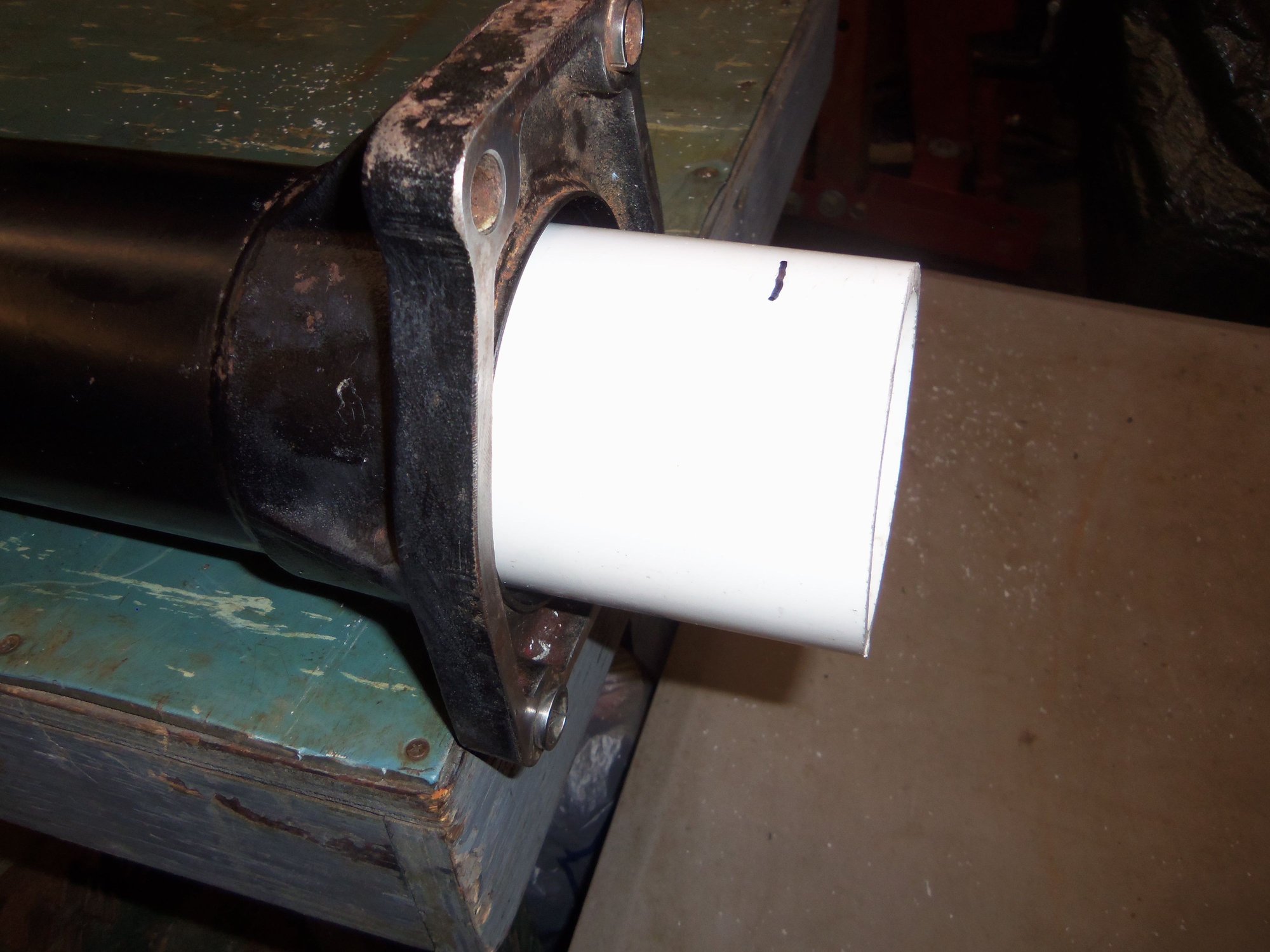
3" OD PVC pipe for pushing cleaning rag through the torque tube.
Simple Green soaked rag draped over the end of the PVC pipe.
Rag started into the torque tube with the PVC pipe.
Bumping the PVC pipe on the concrete like a fence post driver.
Rag and PVC pipe just starting to push through.
Rag and pipe pushed all the way through. Repeat as necessary.
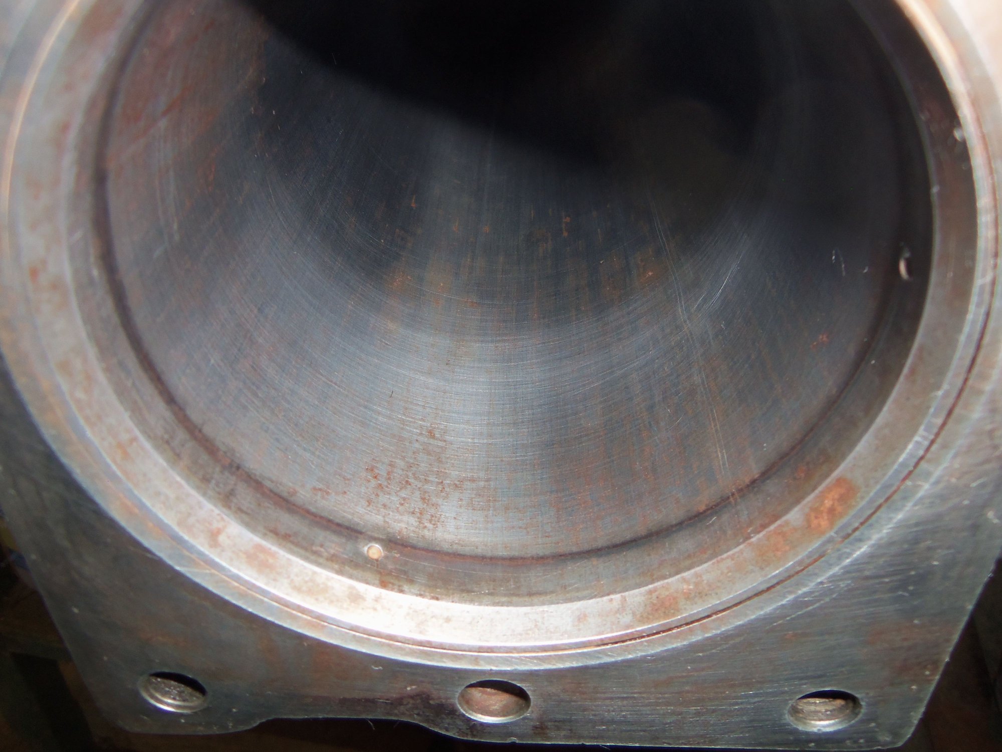
Transmission end is clean.
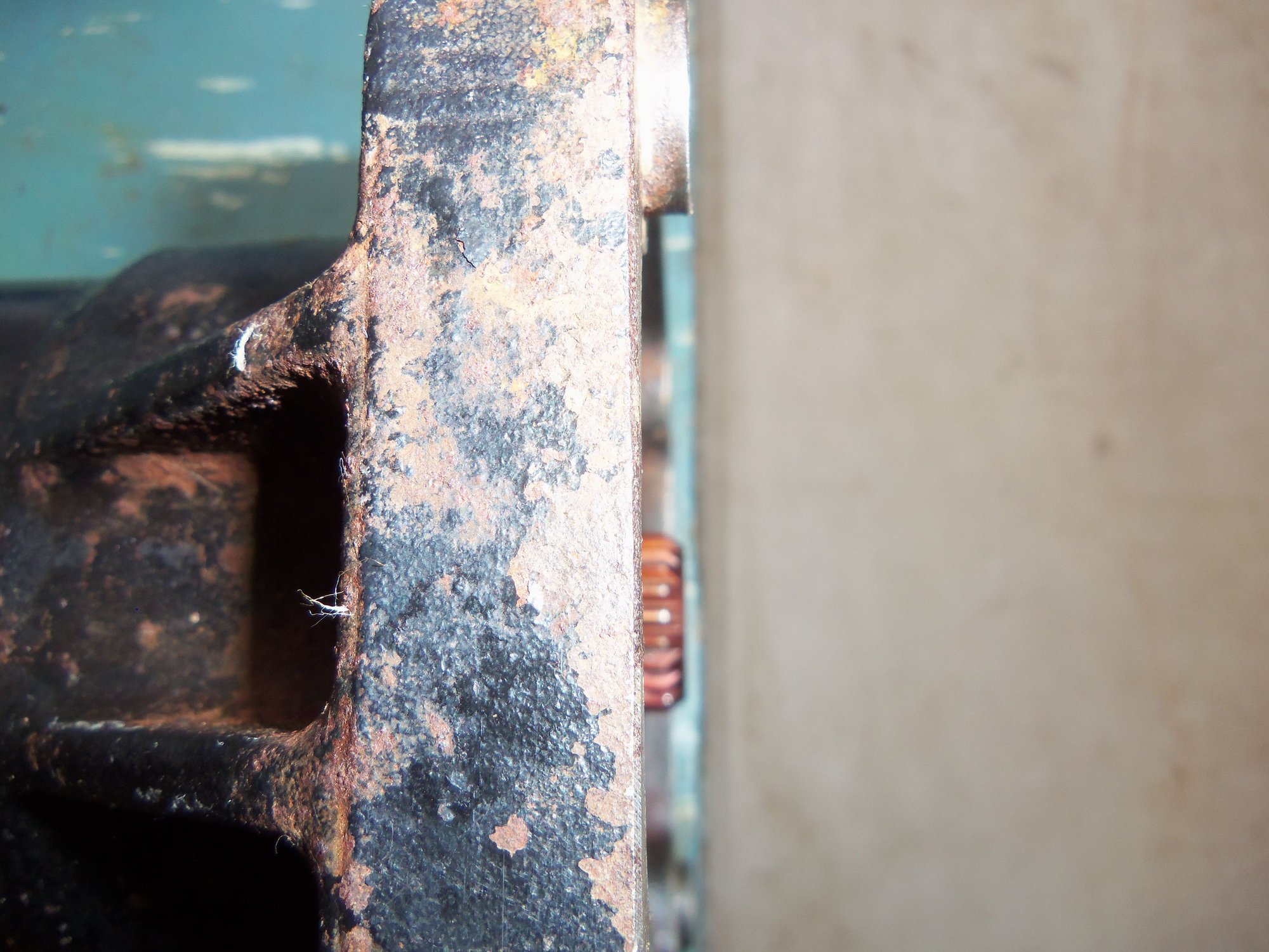
Engine end has some surface rust.
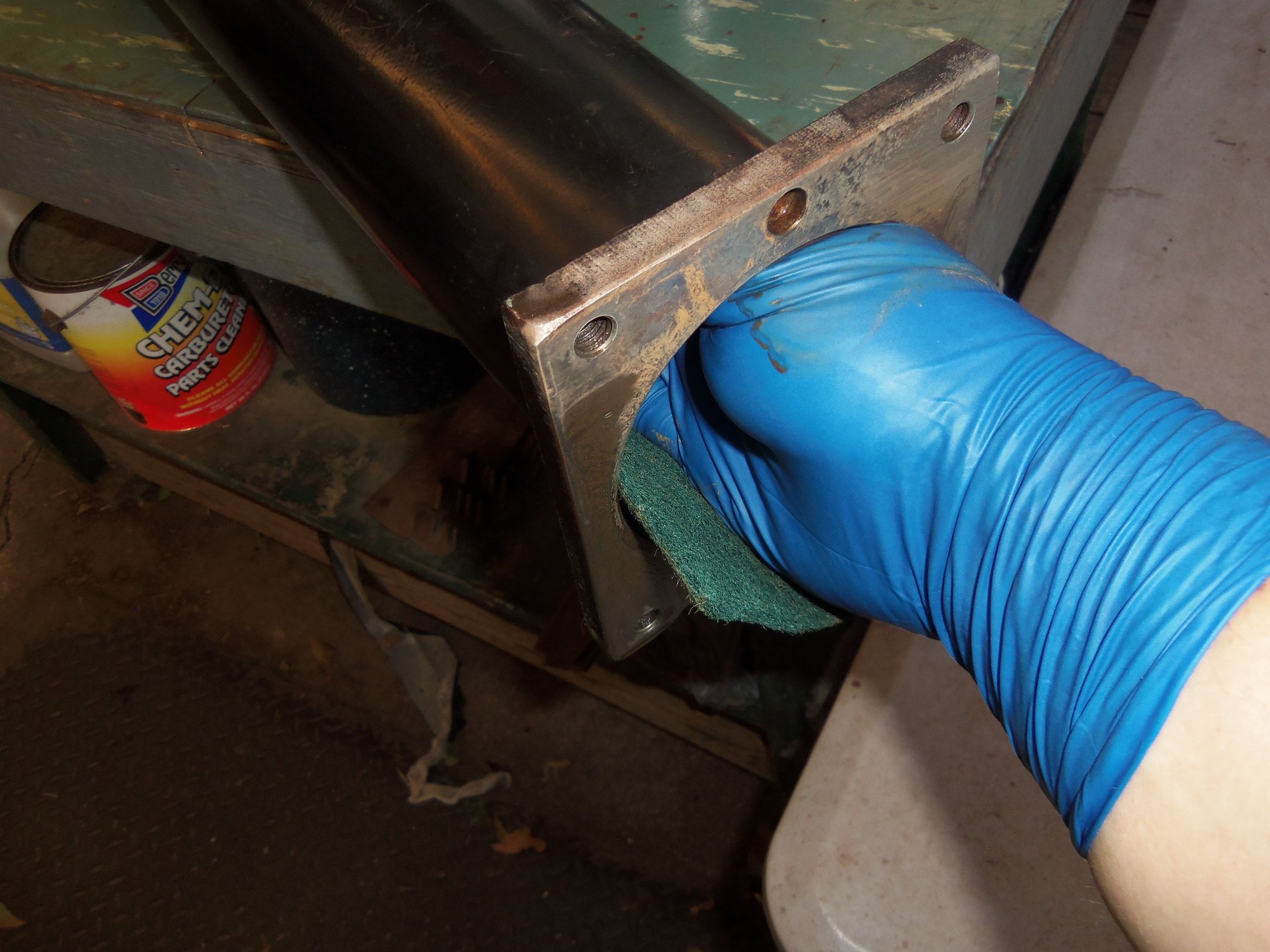
Scrubbing the surface rust with a mineral spirits soaked Scotchbrite pad. Yes, I am a sissy and wear nitrile gloves. The chemical headaches and skin rashes of my bare-handed youth are no longer as fun as they used to be. Get over it.
Engine end of tube is not perfect, but will do.
Transmission end of tube looks better.
Next was bearing and vibration damper installation. RIGHT OFF THE BAT, let me be clear: I reinstalled the vibration damper with the SuperBearings because I thought it was a good idea. ME. I will catch sh*t from various sides. And don't care. My car. My torque tube. My choice.
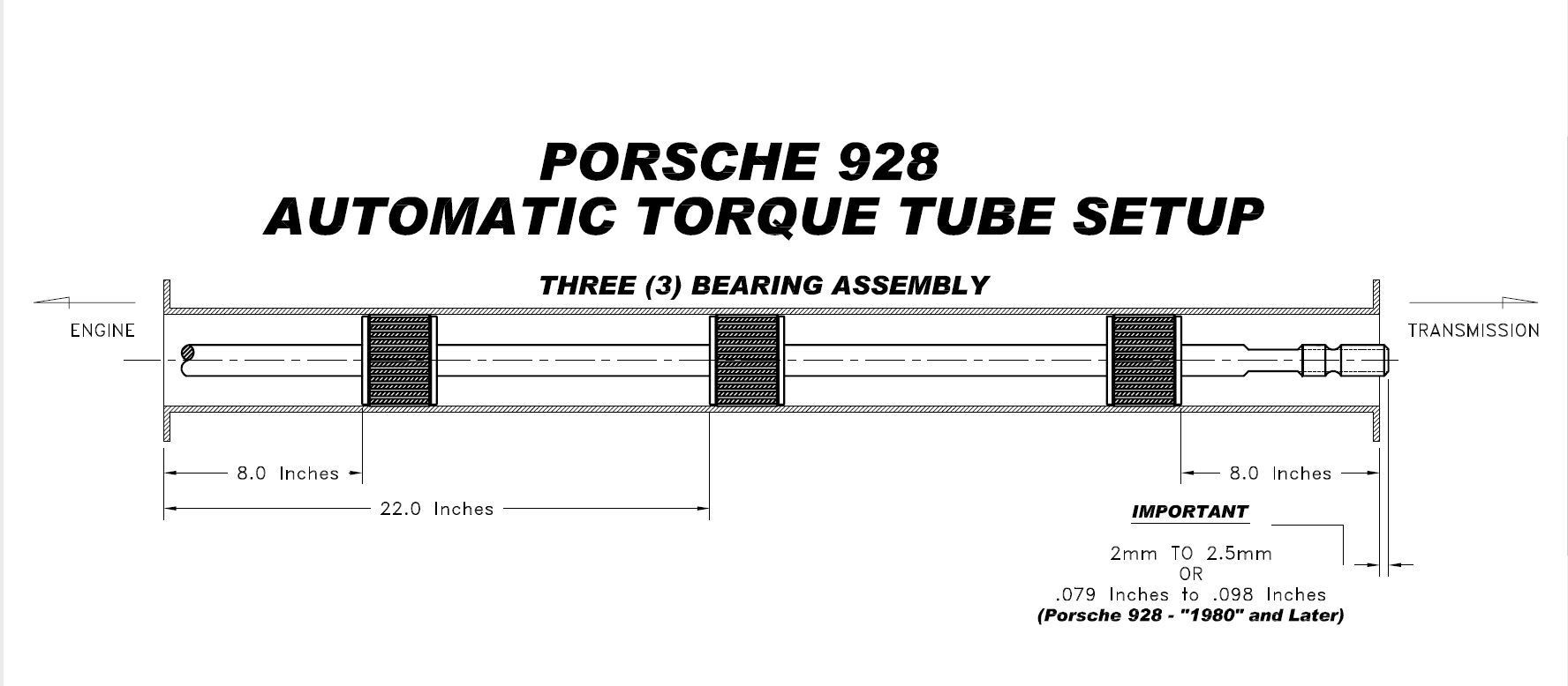
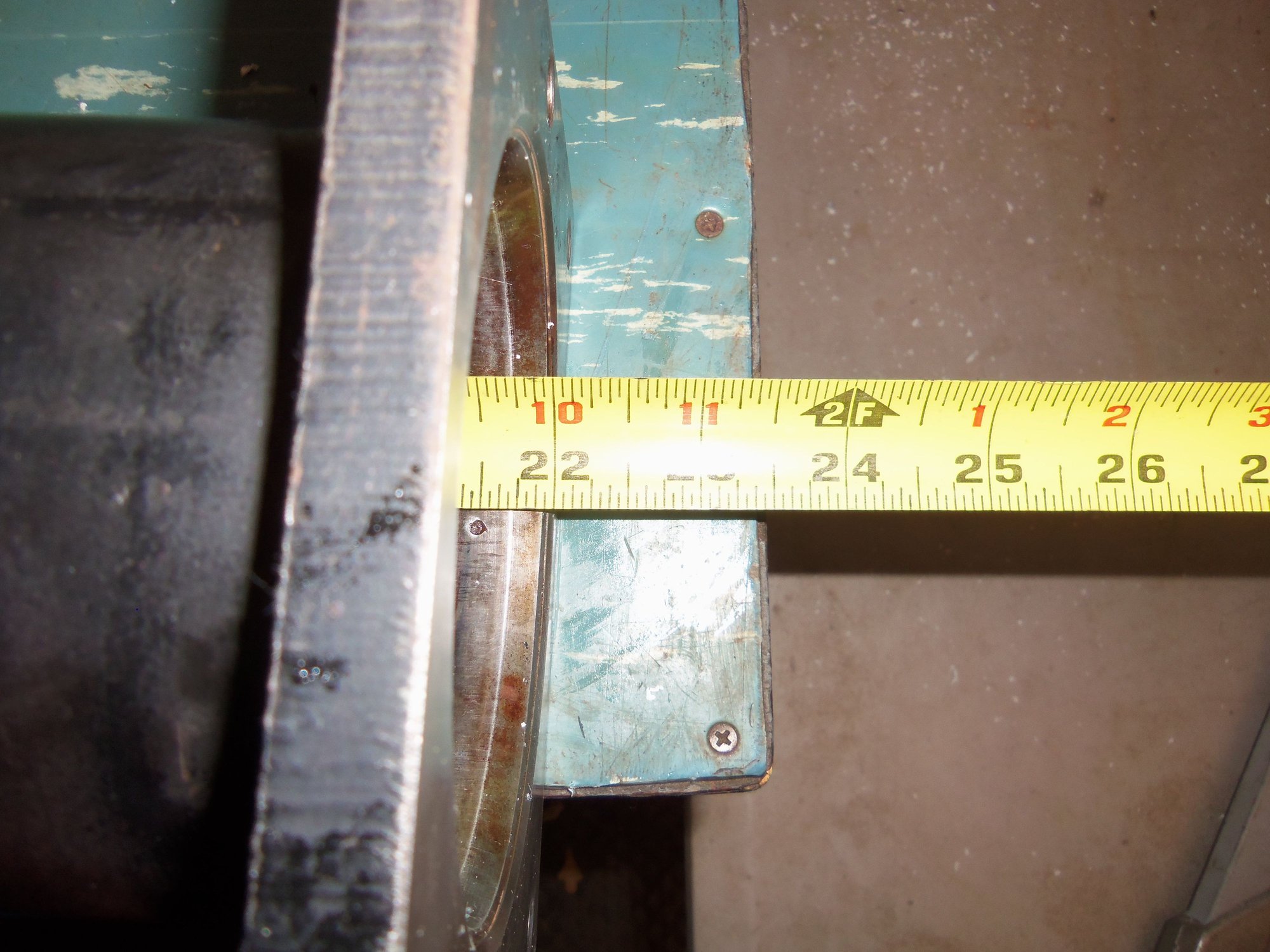
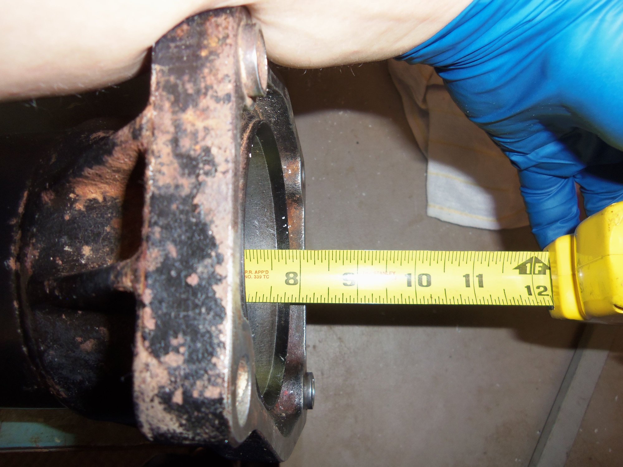
I had to differ slightly in the arrangement of the bearings and vibration damper. To my knowledge, the torque tube on the Red Witch was original. Noone had been in there before me. The arrangement from front to back was bearing - bearing - bearing - damper. With the SuperBearings, the front and rear bearings are to be placed 8" in from the ends of the torque tube. This does not leave enough room for the vibration damper at the back. So...I did some math and placed the vibration damper midway between the middle and rear bearings. I know this is not where Porsche originally put it, but it is what it is.
Now, a preemptive note, and I will put it in red: INSTALL THE VIBRATION DAMPER BEFORE INSTALLING THE SUPERBEARINGS!!!
The force and violence required to push the damper into position caused the two SuperBearings I had already installed to move from their positions. Took a little creative beating on the torque tube to get them back where they belong. The cause of all this are 928 International's recently released vibration damper rubber isolators. They are TIGHT! That is a good thing, though. Once you beat them into position, I don't think they are going to go anywhere. These new isolators are the ONLY reason I considered reinstalling the vibration damper!
I started by installing the middle SuperBearing. After lubricating the inside of the torque tube with the supplied water based lubricant, I was able to push it halfway into the torque tube by hand. I used a rubber mallet, the Constantine supplied pushing disc, and a cut section of the 3" PVC pipe to hammer the bearing the rest of the way into place. Using the same method, I installed the front SuperBearing. Then came the vibration damper...
This thing was a b*tch in high heels! It took a bit of force to install the new isolators onto the vibration damper itself. Feeling flush from installing two SuperBearings, I went to push the vibration damper right on into the tube. Nope. The first isolator just started into the tube and stopped. Note: I installed the bearings with the torque tube vertically oriented on a wood 4x4. I had the torque tube oriented the same to install the damper. I took the installation disc and the rubber mallet and started hammering. The vibration damper slowly started moving into the tube. Hammering turned to full on beating. As the vibration damper moved into the tube, I added the cut off section of the PVC pipe. Soon, I decided the rubber mallet was too sissy. Out came the shot filled mallet. And beating recommenced. NOTE: as of this writing, my arms still hurt.
As the damper moved in, it started moving less and less for the beating. I was getting concerned that I was not going to get this damper into position. A dim light bulb went off above my head. I turned the torque tube upside down vertically, so the PVC pipe was resting on the concrete and the vibration damper was resting on the PVC pipe. Using the same fence post driver motion, I banged the torque tube against the PVC pipe. It worked! Still took quite awhile to get the vibration damper into place. However, I look at it this way, for all the effort and violence it took to push the damper into place, it should stay there.
I checked the positions of the already installed front and middle bearings. They had moved towards the front of the torque tube. I banged the back end of the torque tube against the 4x4 on the concrete until the middle bearing was back into position. I then just drove the front bearing back into place with the PVC and rubber hammer.
Installing the vibration damper first would have prevented this headache.
With the all three SuperBearings and the vibration damper installed, I set the torque tube aside. As per conversations with Constantine, I needed to let the SuperBearings 'relax' for 24 hours and to let the installation lubricant dry. Reasoning had to do with the drive shaft. The original drive shaft had wear on the rear splines. I have a new Greg Brown 300M drive shaft. As per Constantine, the GB shaft is slightly larger OD than the original shaft. This means it will take a little more force to push the shaft through the SuperBearings. Such force could cause the bearings to move out of place if the lubricant isn't dry. So, I let it sit.
SuperBearings location in automatic torque tube, from Constantine.
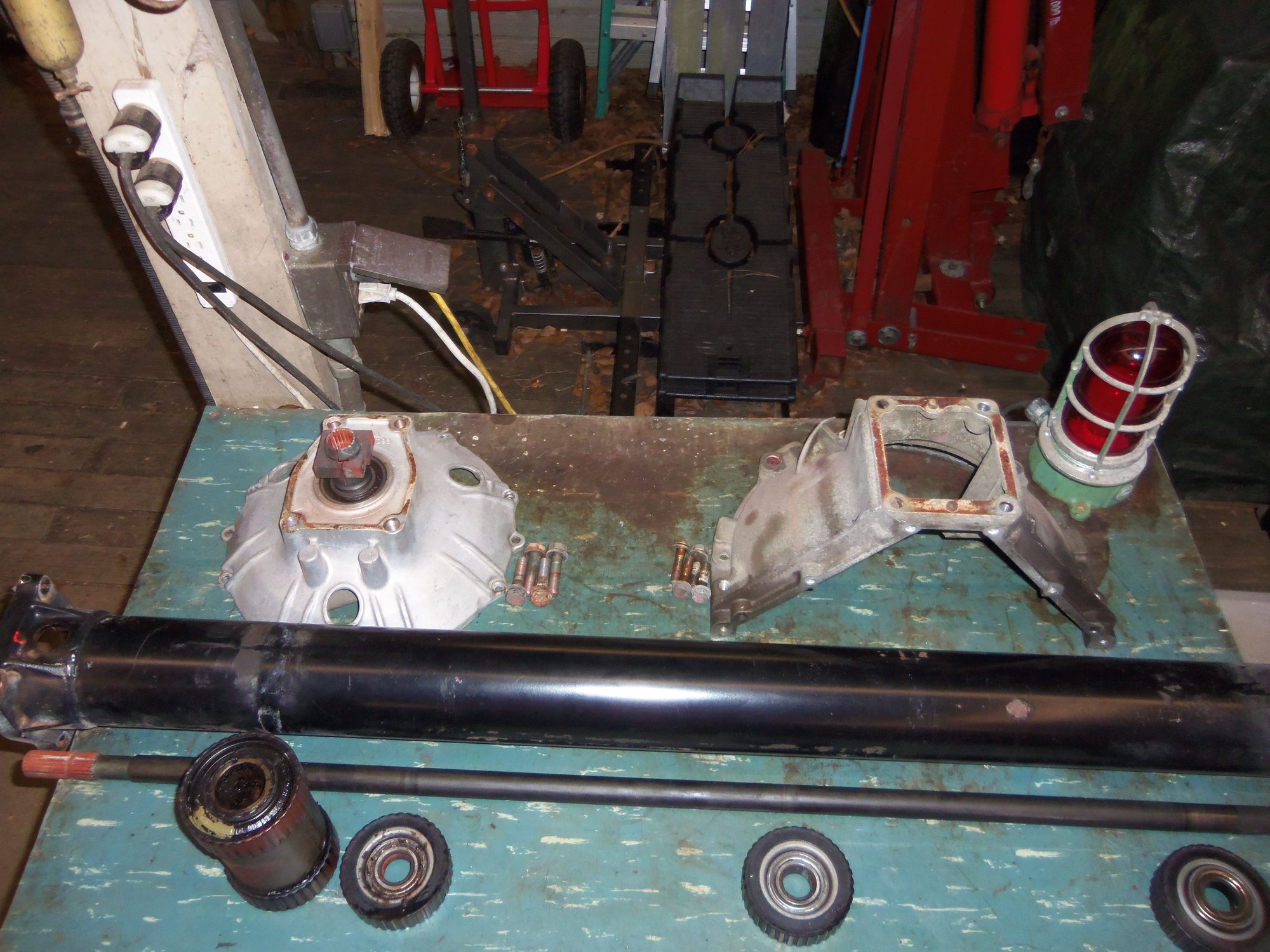
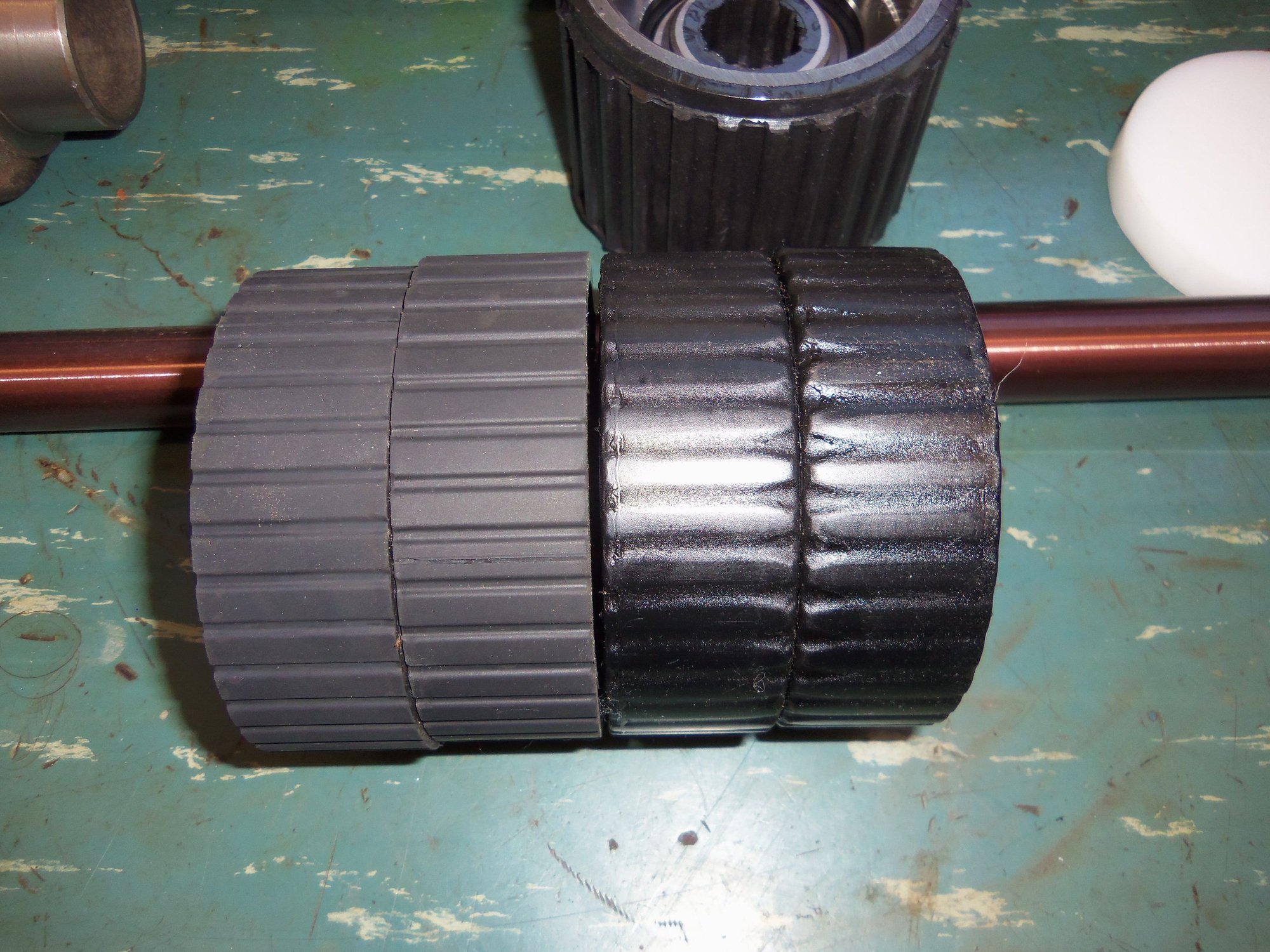
Arrangement of vibration damper and original bearings when I disassembled the torque tube. Vibration damper was at the back of the torque tube.
Arrangement of vibration damper and SuperBearings as I reassembled the torque tube. Vibration damper is now between the middle and rear bearing.
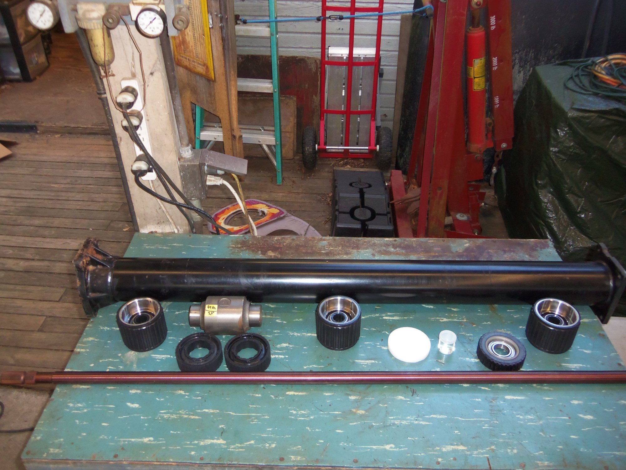
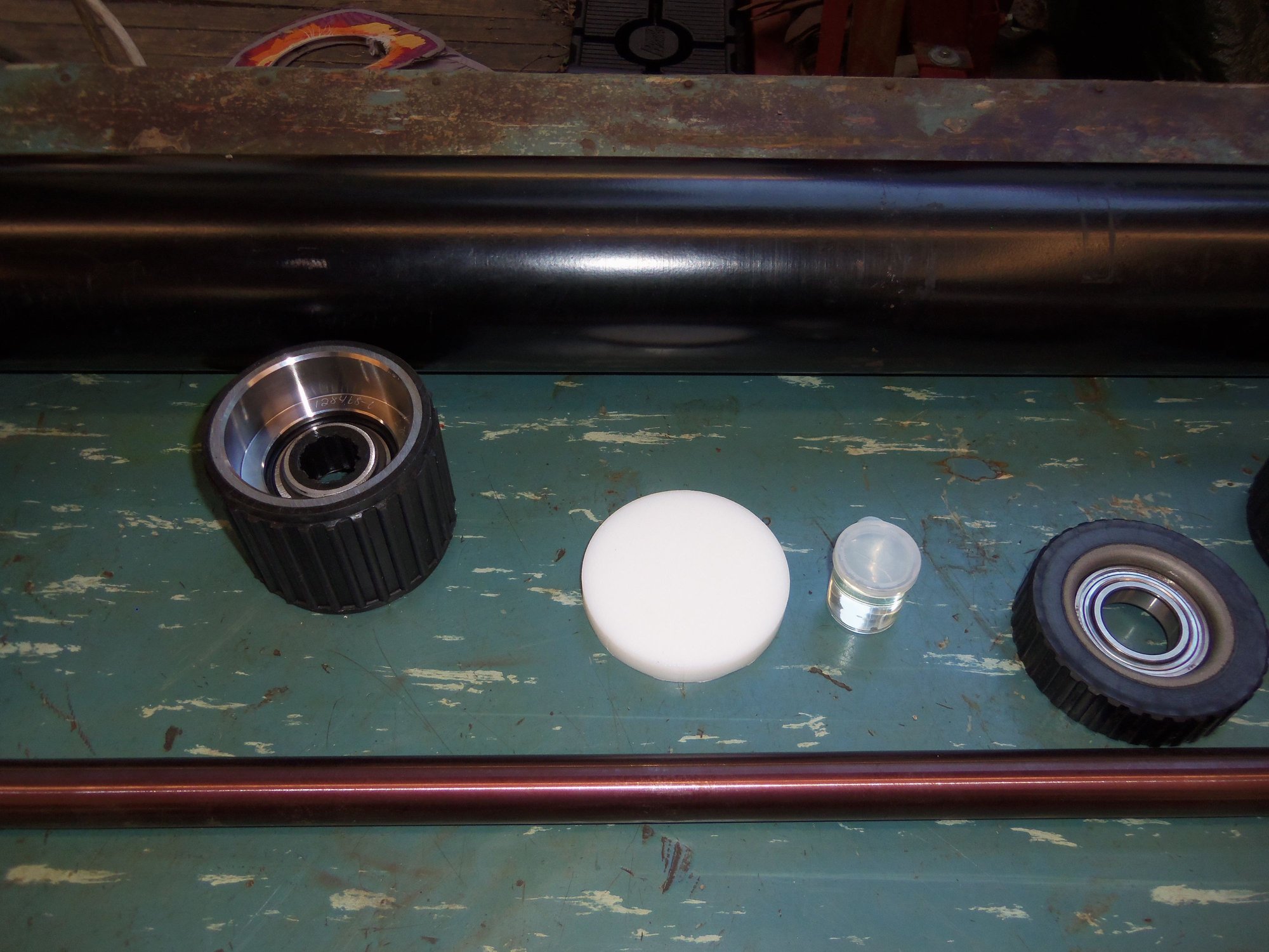
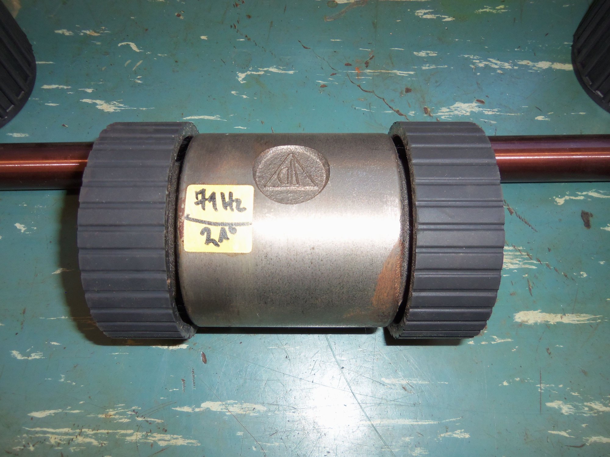
Rear SuperBearing, vibration damper, new rubber isolators, and Greg Brown 300M driveshaft.
Middle SuperBearing, installation disc, and water based lubricant.
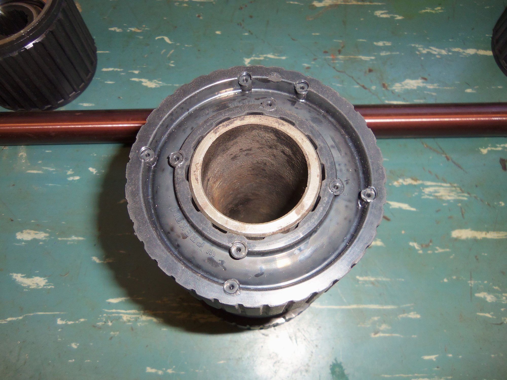
Front SuperBearing and original bearing housing for use as a guide.
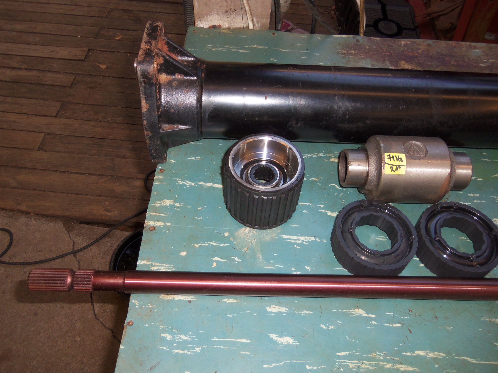
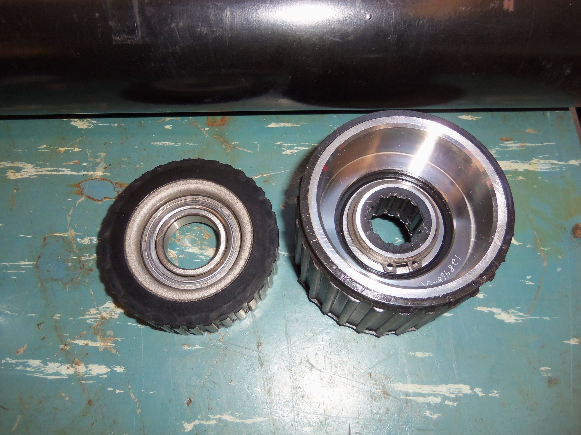
Comparing original bearing with SuperBearing.
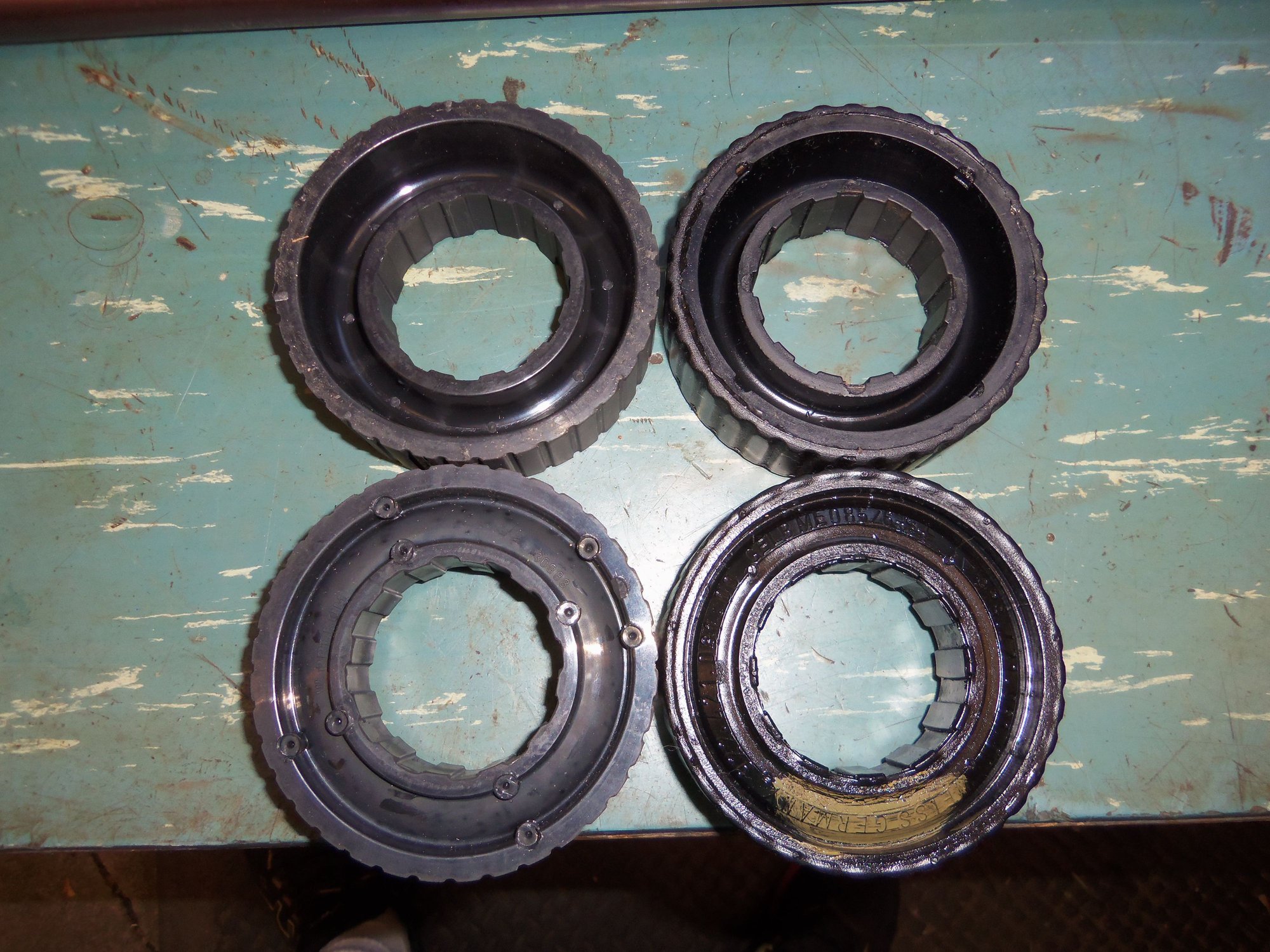
New 928 International vibration damper rubber isolators on the left, worn original isolators on the right.
New 928 International rubber isolators on the left, worn originals on the right. Note how the isolators are 'cupped'. Deeper part of the cup is shown at top, and faces in on the vibration damper.
New isolators installed on the vibration damper.
New isolator oriented on the vibration damper as was the original.
Orientation of original rubber isolator on vibration damper.
Starting a SuperBearing by hand into the torque tube.
As per Constantine's instructions, spiral clip end of bearing housing faces towards the engine. All three SuperBearings are oriented this way.
Using PVC pipe section to hammer SuperBearing into place.
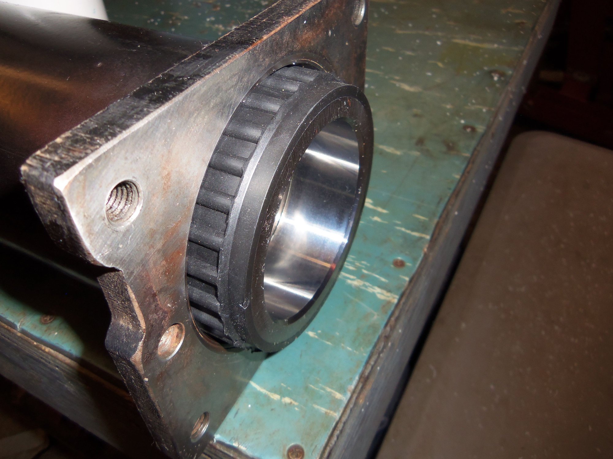
Middle SuperBearing in place, 22" from the front flange.
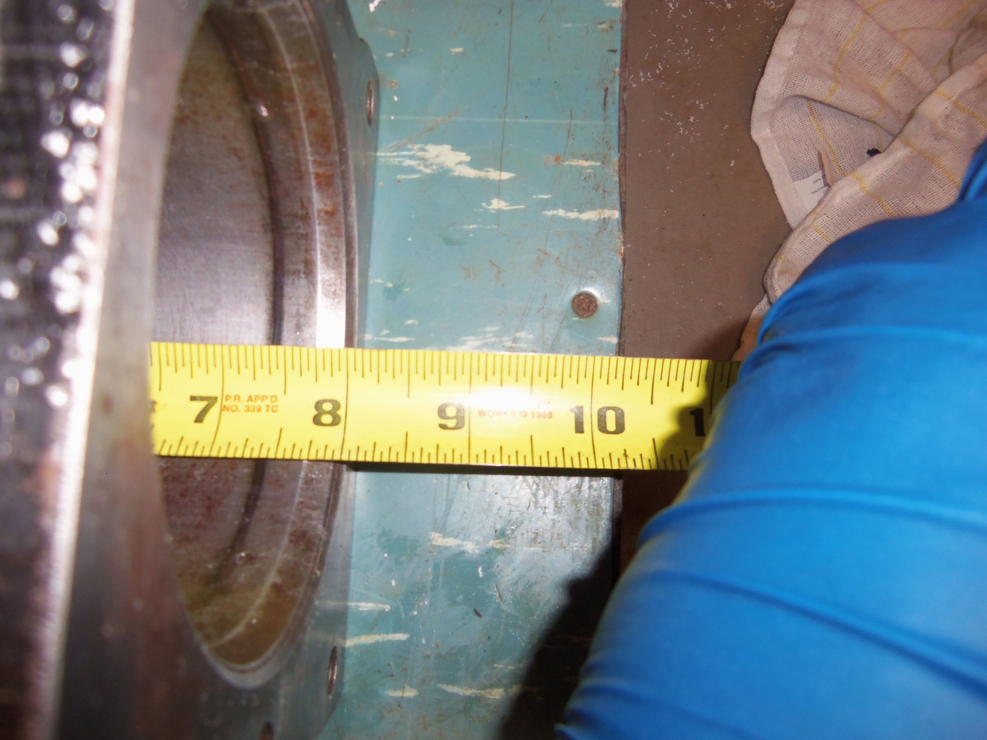
Front SuperBearing in place, 8" from the front flange.
Beating the vibration damper into place, fence post driver style.
Mark on the PVC pipe to tell me when to stop beating the torque tube against the PVC so that the vibration damper was in place.
Rear SuperBearing in place, 8" from the rear flange.
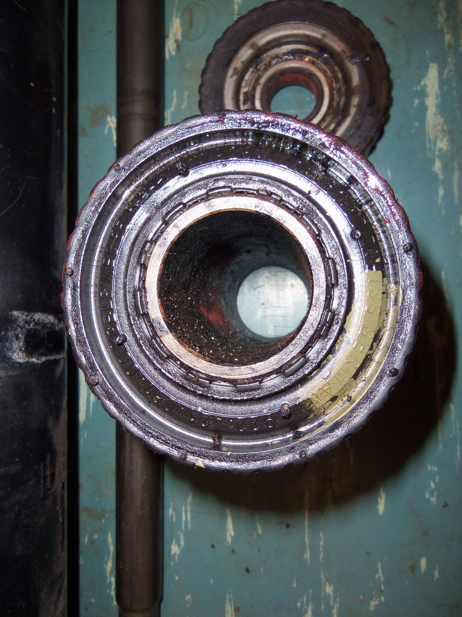
Front bearing installed.
Rear bearing installed. If you look close, you can see the circlip side is facing the transmission.
The next evening, I installed the driveshaft. It too was a b*tch in high heels. Pushing it through the SuperBearings took more force than I expected.
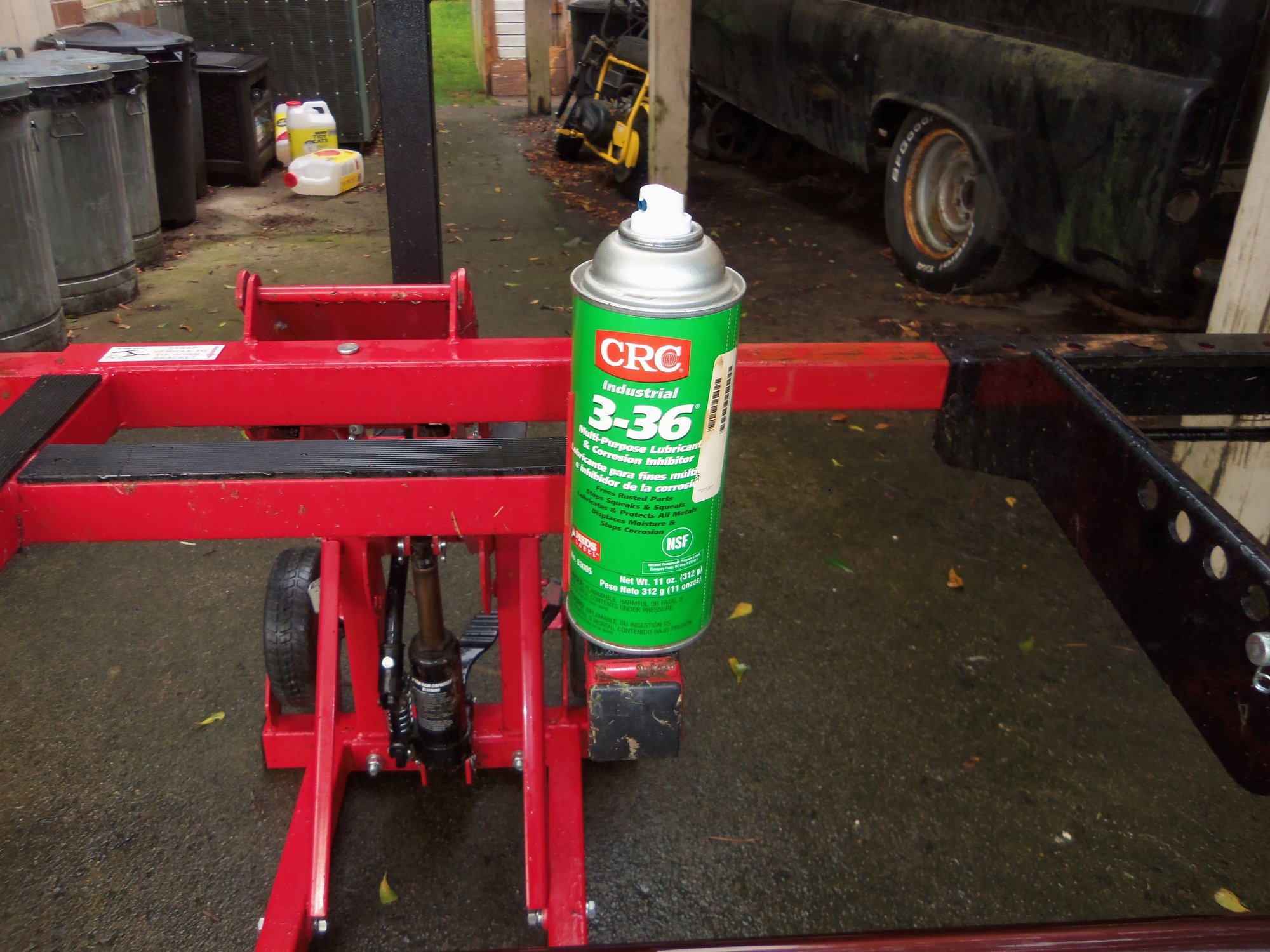
Prior to installation, I sprayed the entire drive shaft with CRC 3-36 lubrication and corrosion inhibitor. Greg Brown suggested I spray the shaft with some sort of long lasting corrosion preventative.
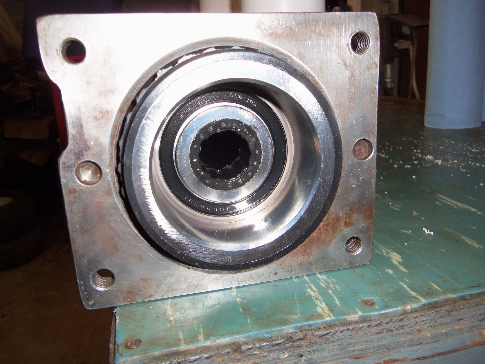
I tapped an old bearing housing halfway into the engine(front) end of the torque tube. This acted as a guide for the drive shaft into the front bearing.
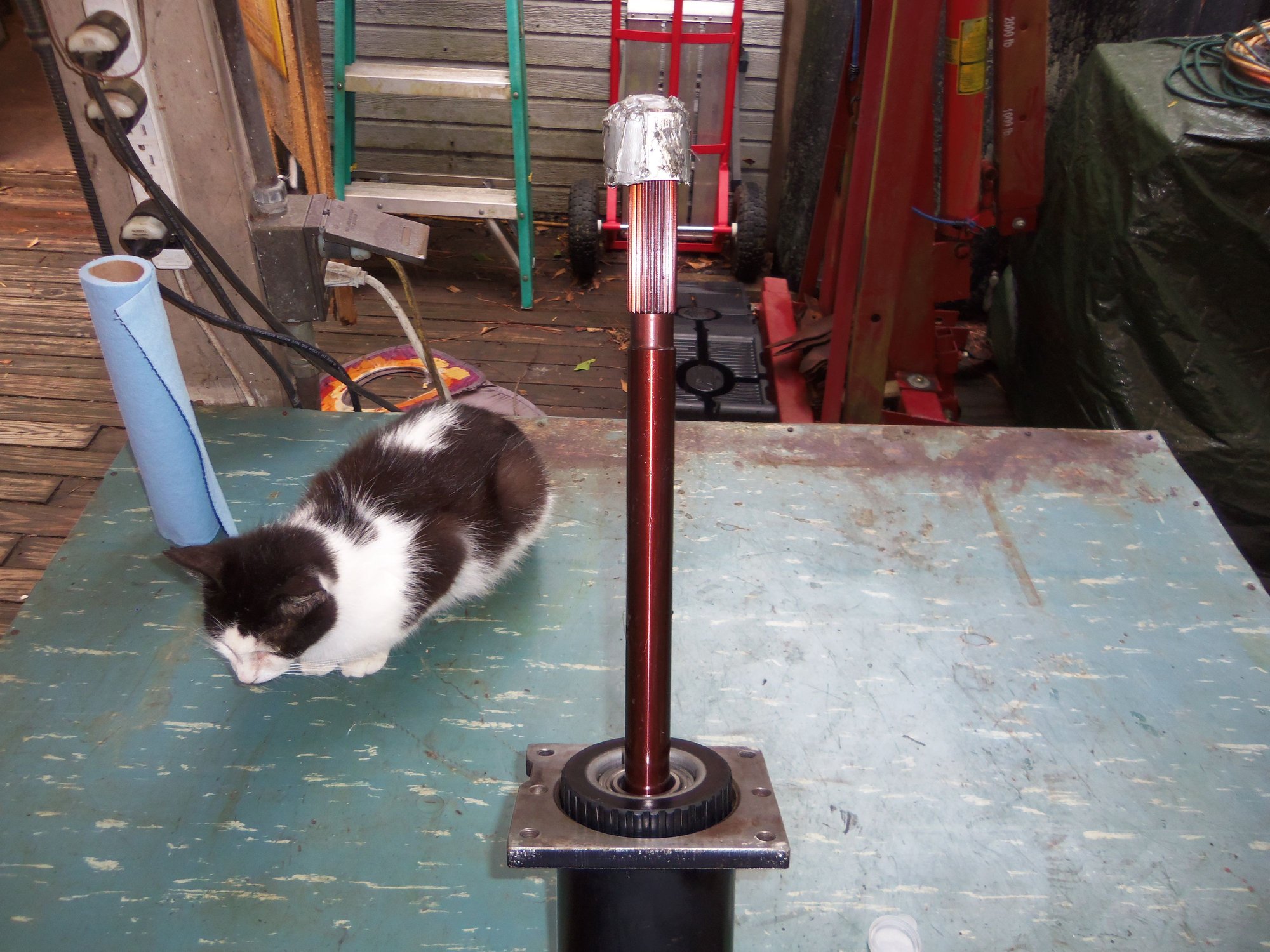
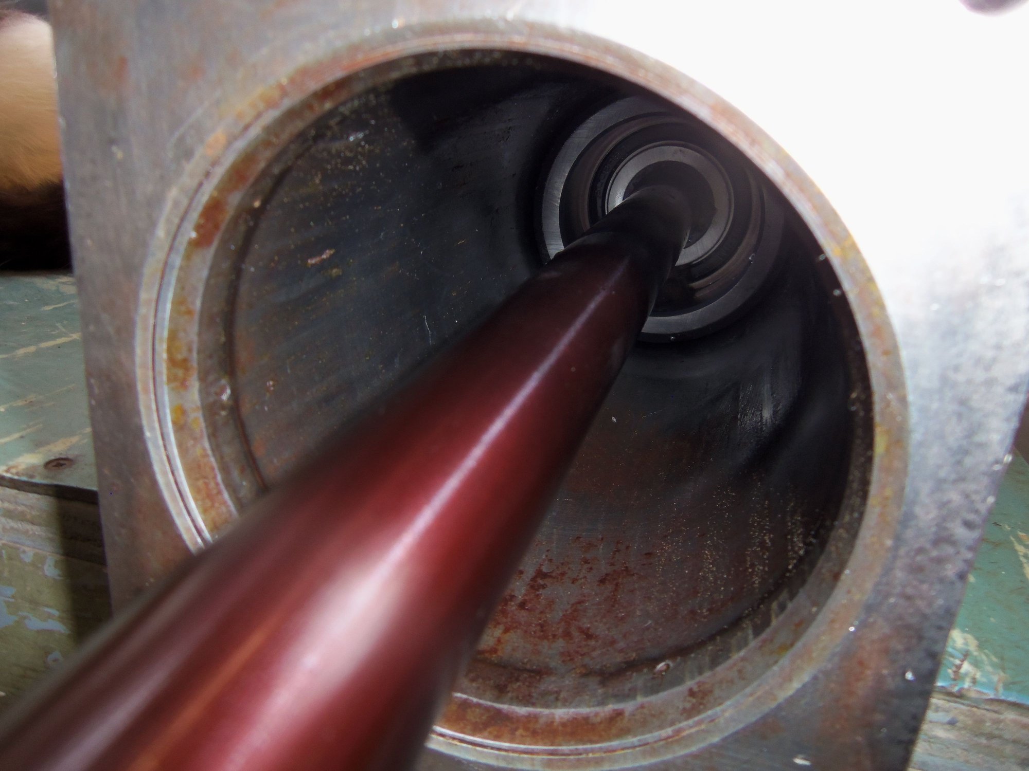
After lubricating the transmission end splines and the body of the drive shaft with the rest of the supplied water based lubricant, I started pushing the drive shaft into the SuperBearings. I started this process with the torque tube laying horizontally on the work bench. Once the shaft was pushed into the front SuperBearing, I oriented the torque tube vertically. From that point, it was just a matter of pushing slowly and evenly. With alot of force. It took most of what I had to push the drive shaft through all the SuperBearings. I took the PVC pipe cap from the drive shaft shipping tube and used it as a palm protector. I was pulling against the front splines with one and and pushing against the pipe cap on the end of the drive shaft with the other hand. Eventually, I got it most of the way in.
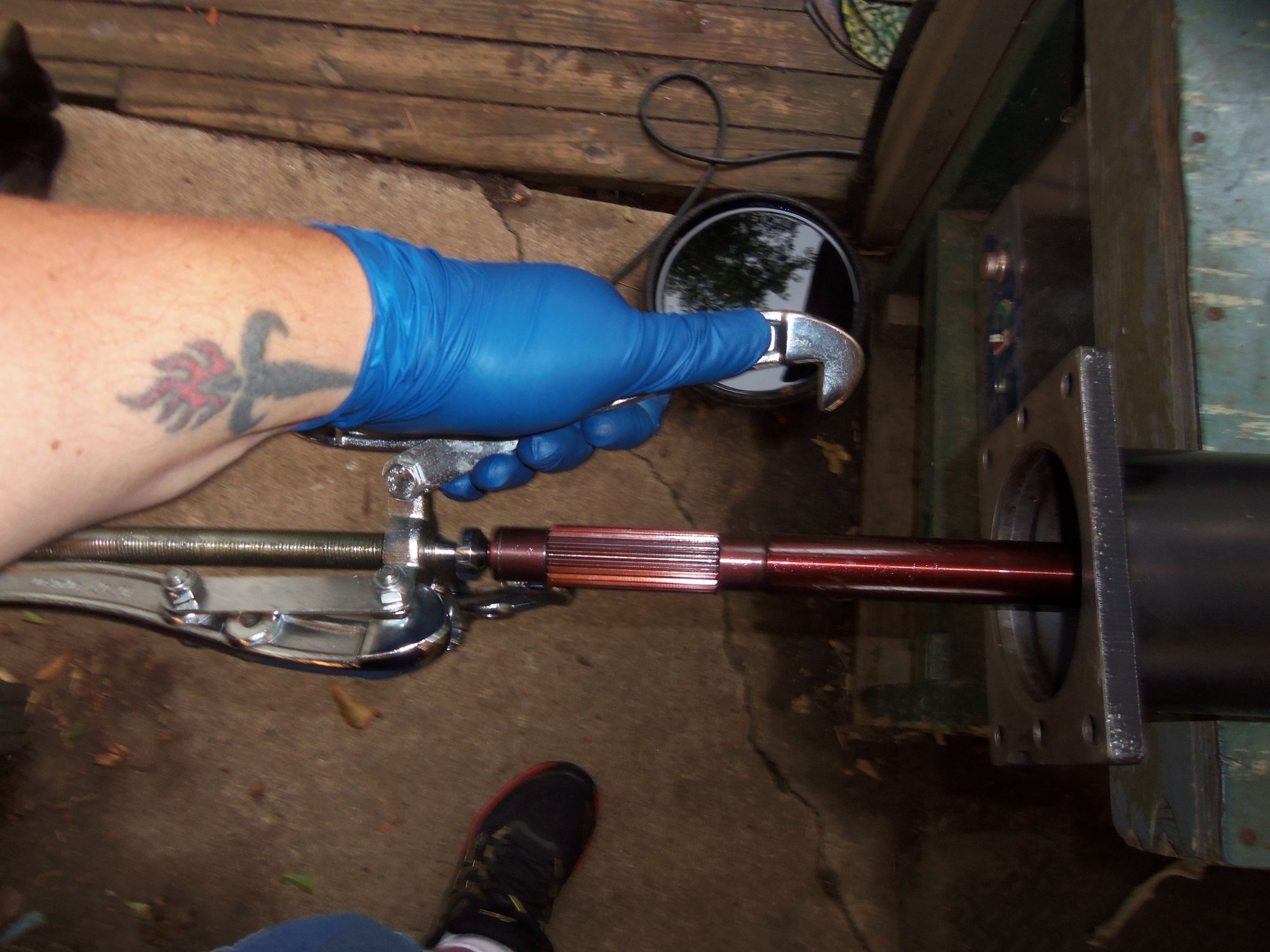
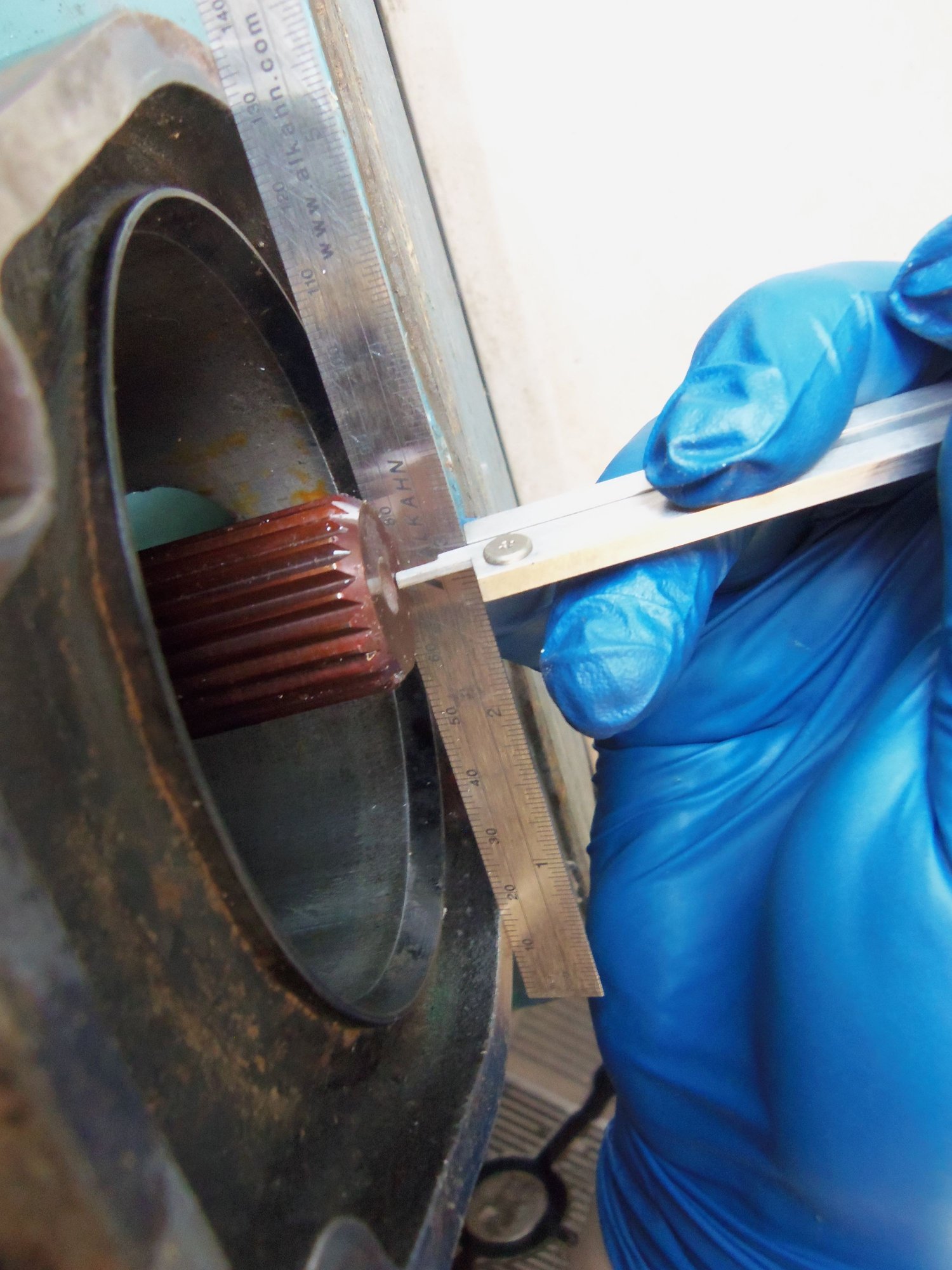
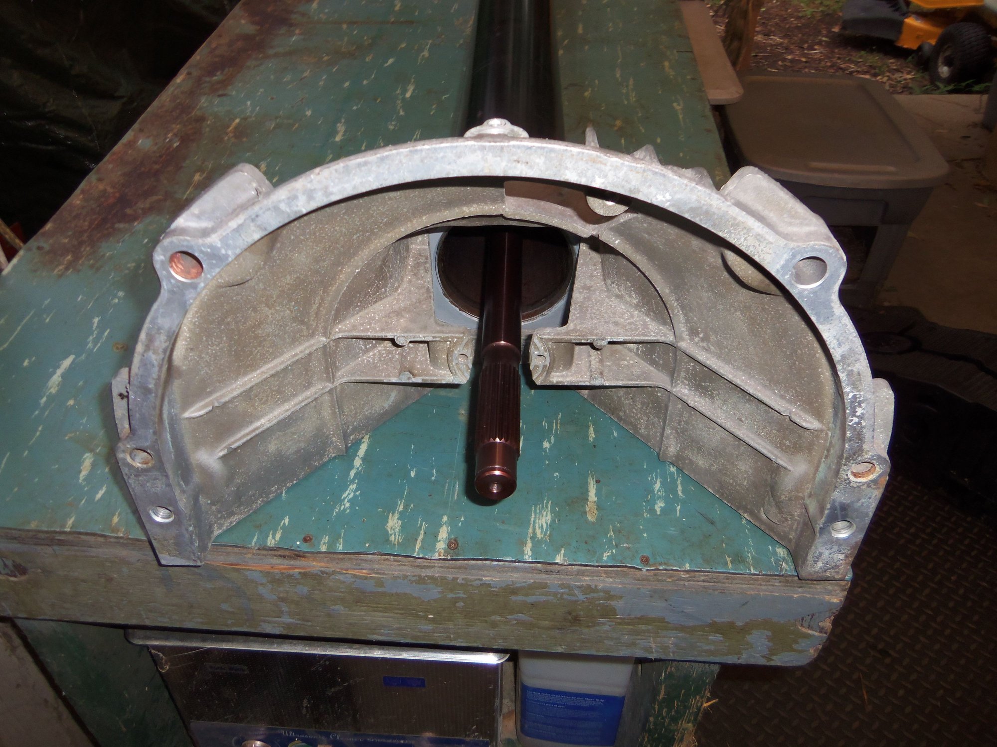
At this point, the forum posts and Constantine's instructions say to use a large bearing puller to push the shaft for final positioning. The transmission end of the shaft should protrude 2.0 - 2.5mm from the end of the torque tube. Yeah...my puller was not manly enough. So...Dwayne had mentioned that his shaft ended up in just the right place with the torque tube on the floor and him pushing. The two alignment rings in the transmission end casting acted as a spacer. So, I tried it. I set the transmission end of the torque tube on the 4x4 wood block, ensuring it was resting on the alignment rings. Once again I pushed hard. Using calipers and a straight edge, I measured the shaft protrusion at 2.26mm. Result!
However...I screwed up. Even though I pushed slowly and evenly, the force it took to go through the bearings caused the front bearing to move out of position. It is now 9" from the front of the torque tube instead of 8" I am going to have to live with this. Short of completely disassembling the torque tube again (which isn't going to happen), I don't know of any way to pull the front bearing to the front. So be it. I think it will be OK.
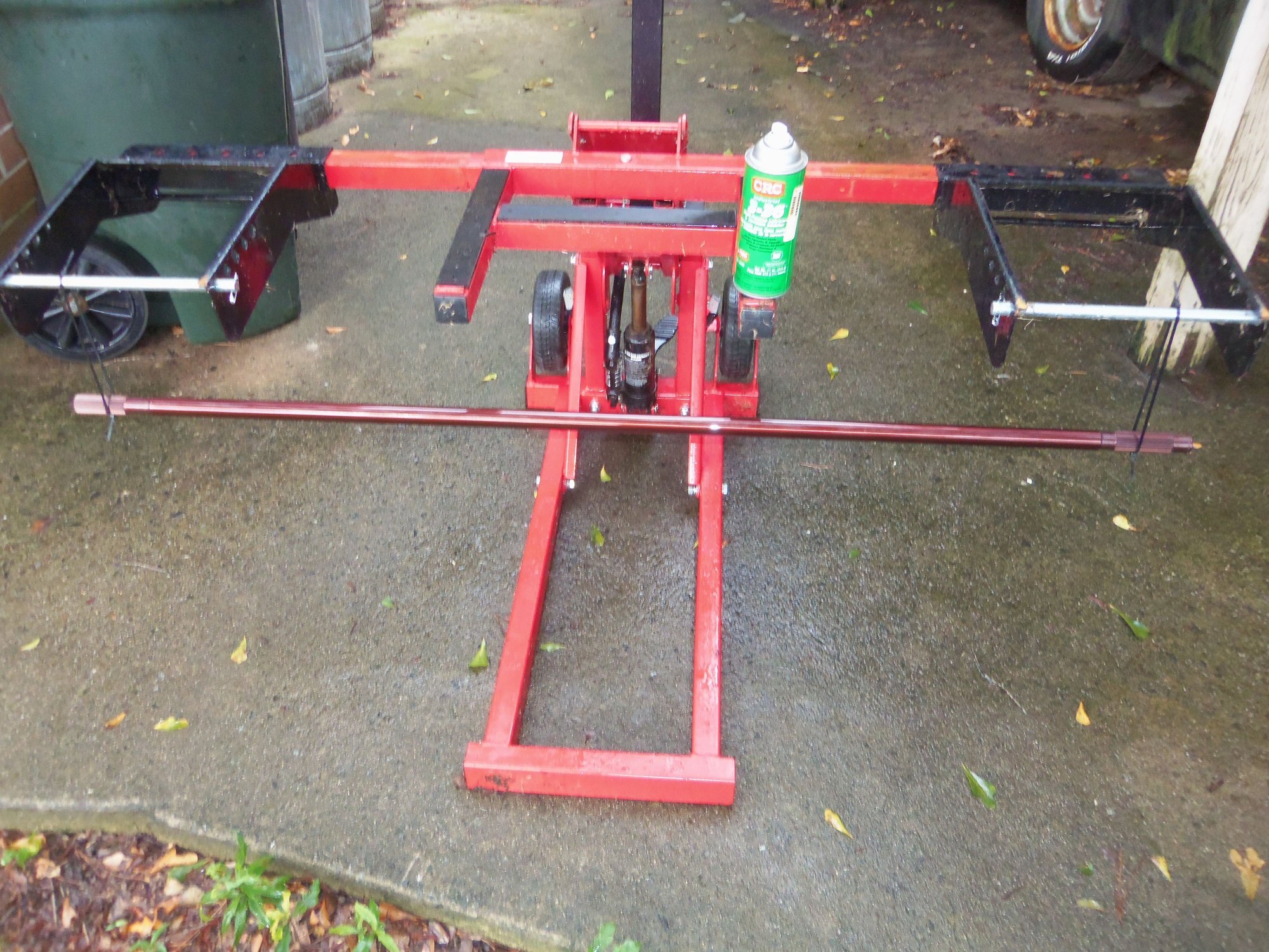
Hung the drive shaft from my garden tractor lift to spray it with corrosion preventative.
CRC 3-36 dries to a sticky film. I like it. Granted, pushing the drive shaft through the SuperBearings will wipe most of this off.
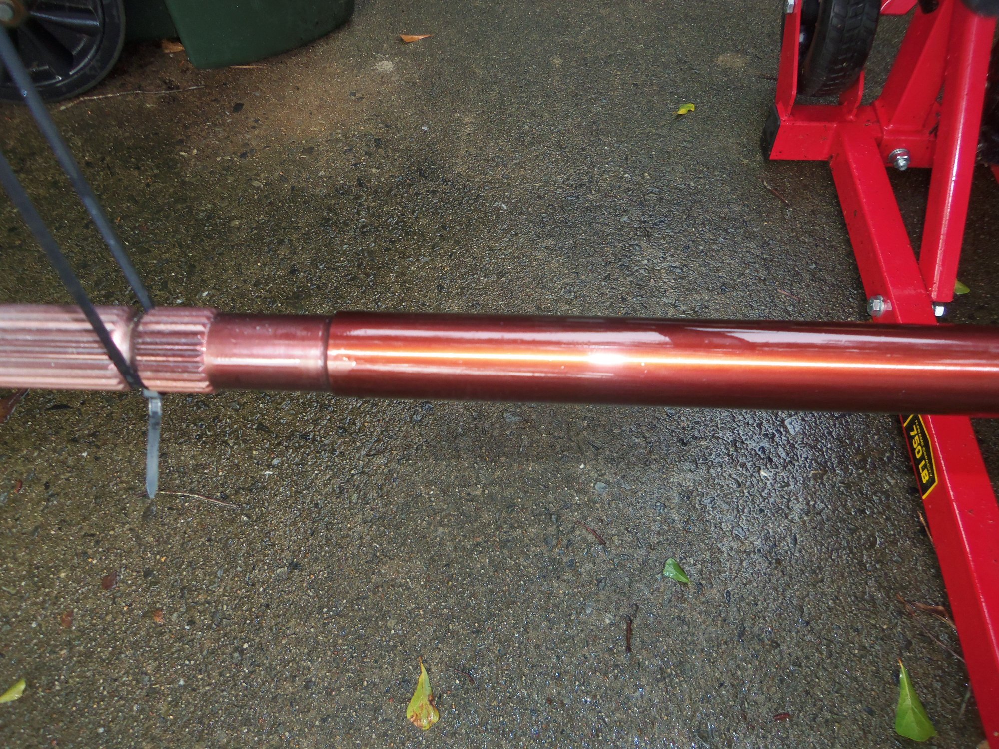
I did leave the rear splines dry. WSM calls for Optimoly HT on them anyway.
I left the front splines dry as well.
Partway through pushing the drive shaft through the SuperBearings.
PVC pipe cap from the drive shaft shipping tube. Made my palm hurt less when pushing on the driveshaft.
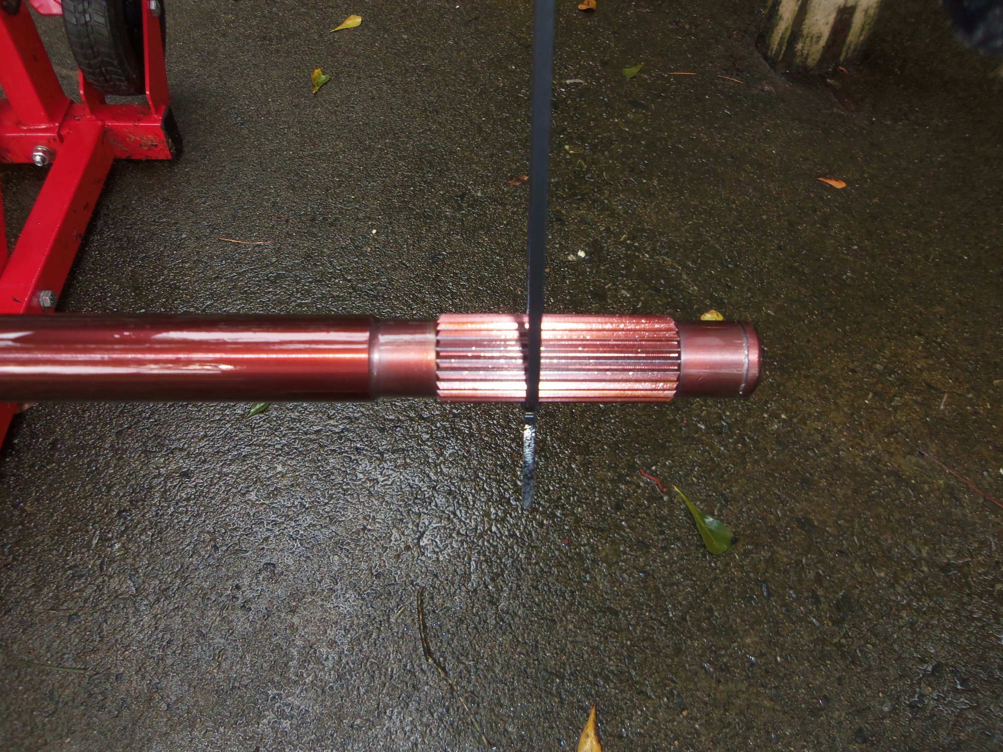
Transmission end splines.
No protrusion of the shaft.
My bearing puller is not manly enough.
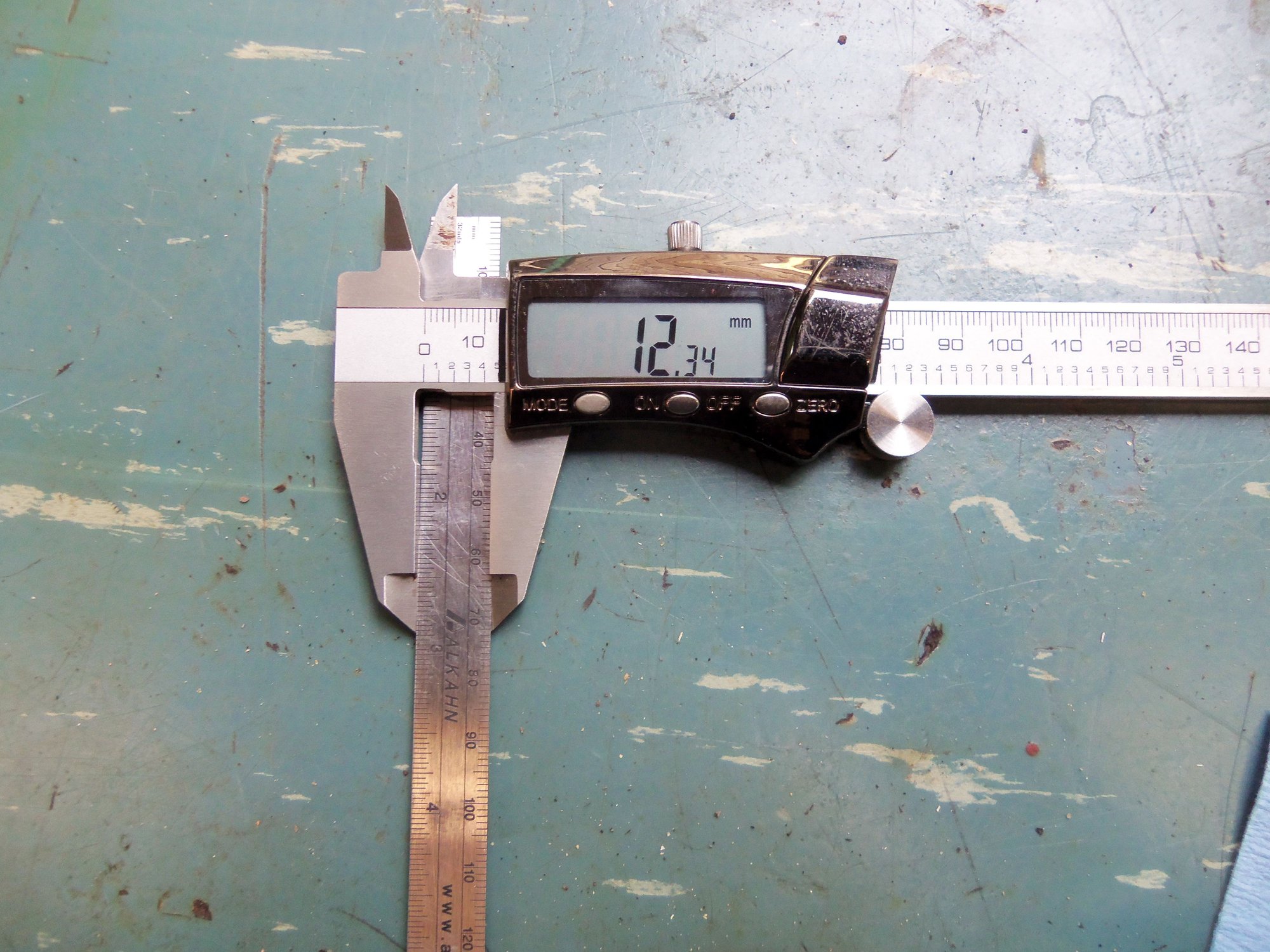
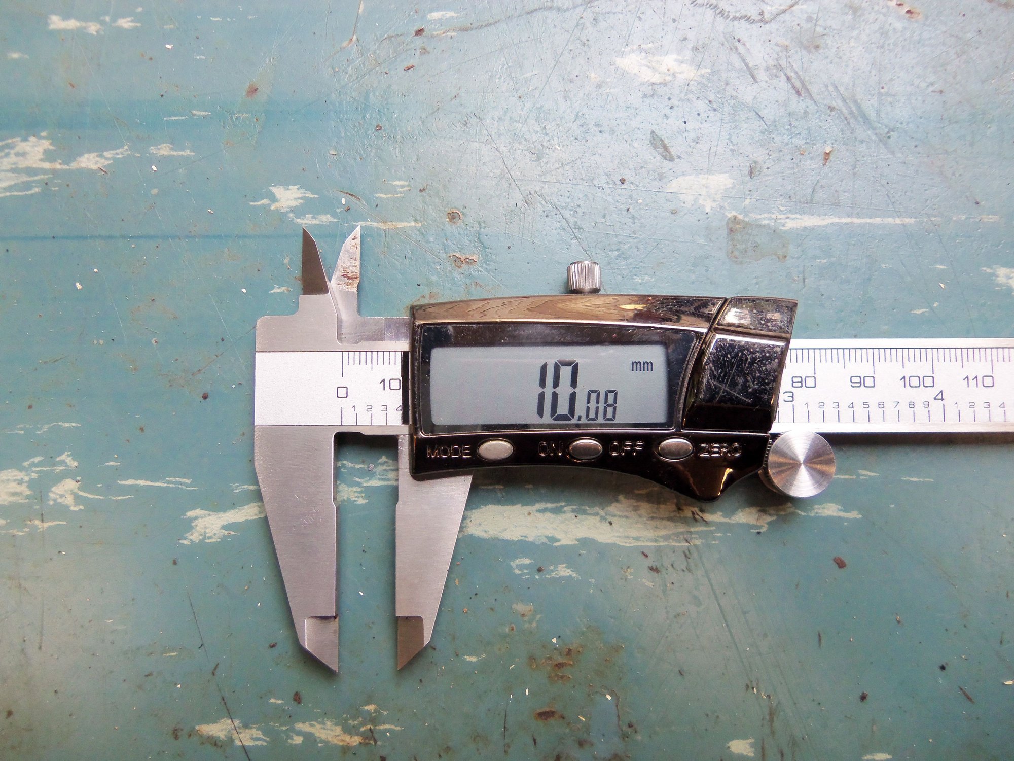
Width of straight edge.
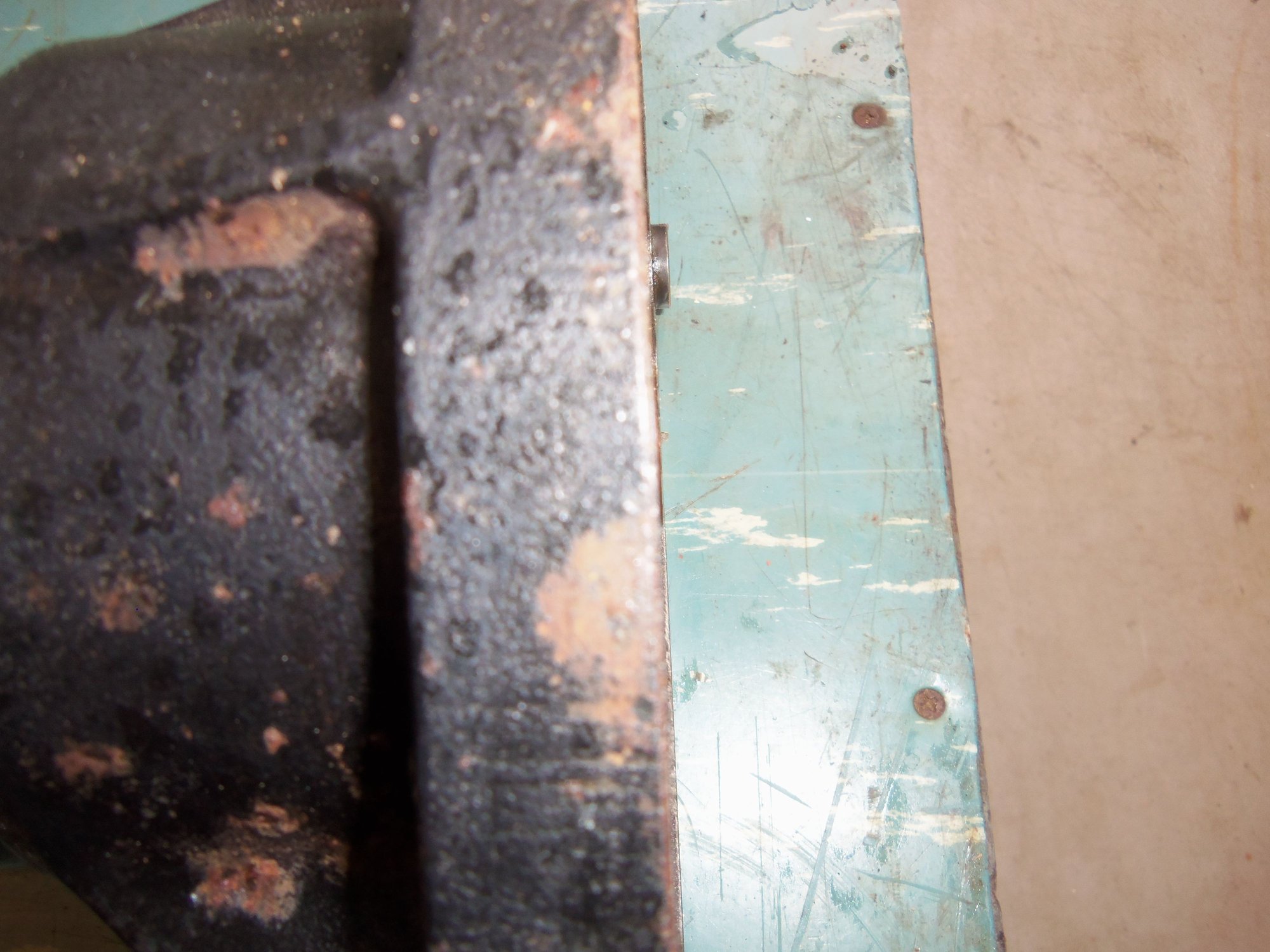
Measuring protrusion of the shaft.
Measurement. Subract from width of the straight edge gives us 2.26mm.
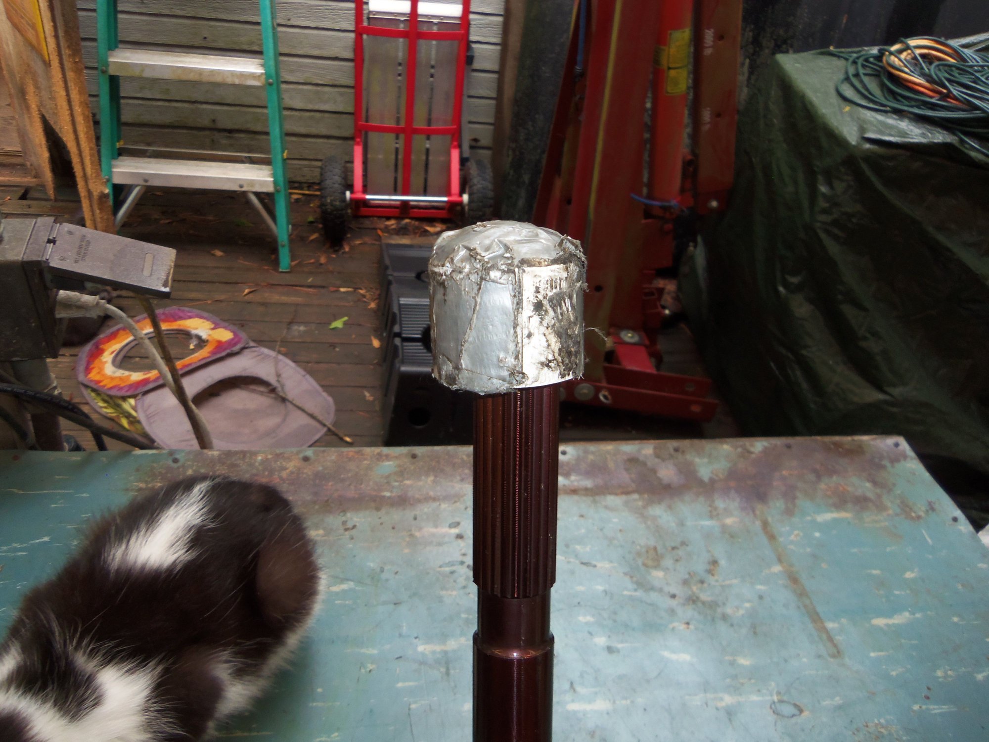
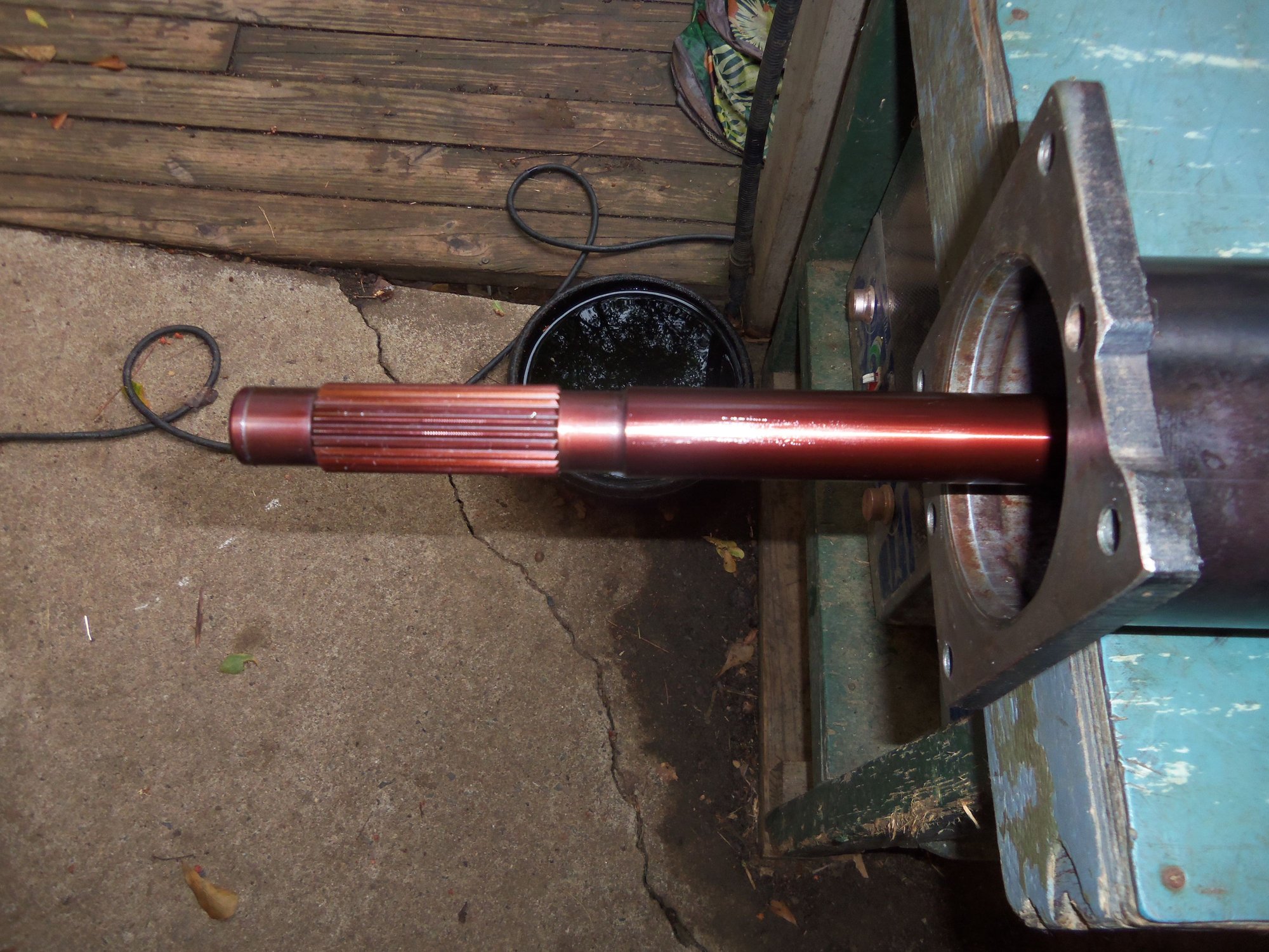
2.26mm protrusion of the drive shaft from the transmission end of the torque tube.
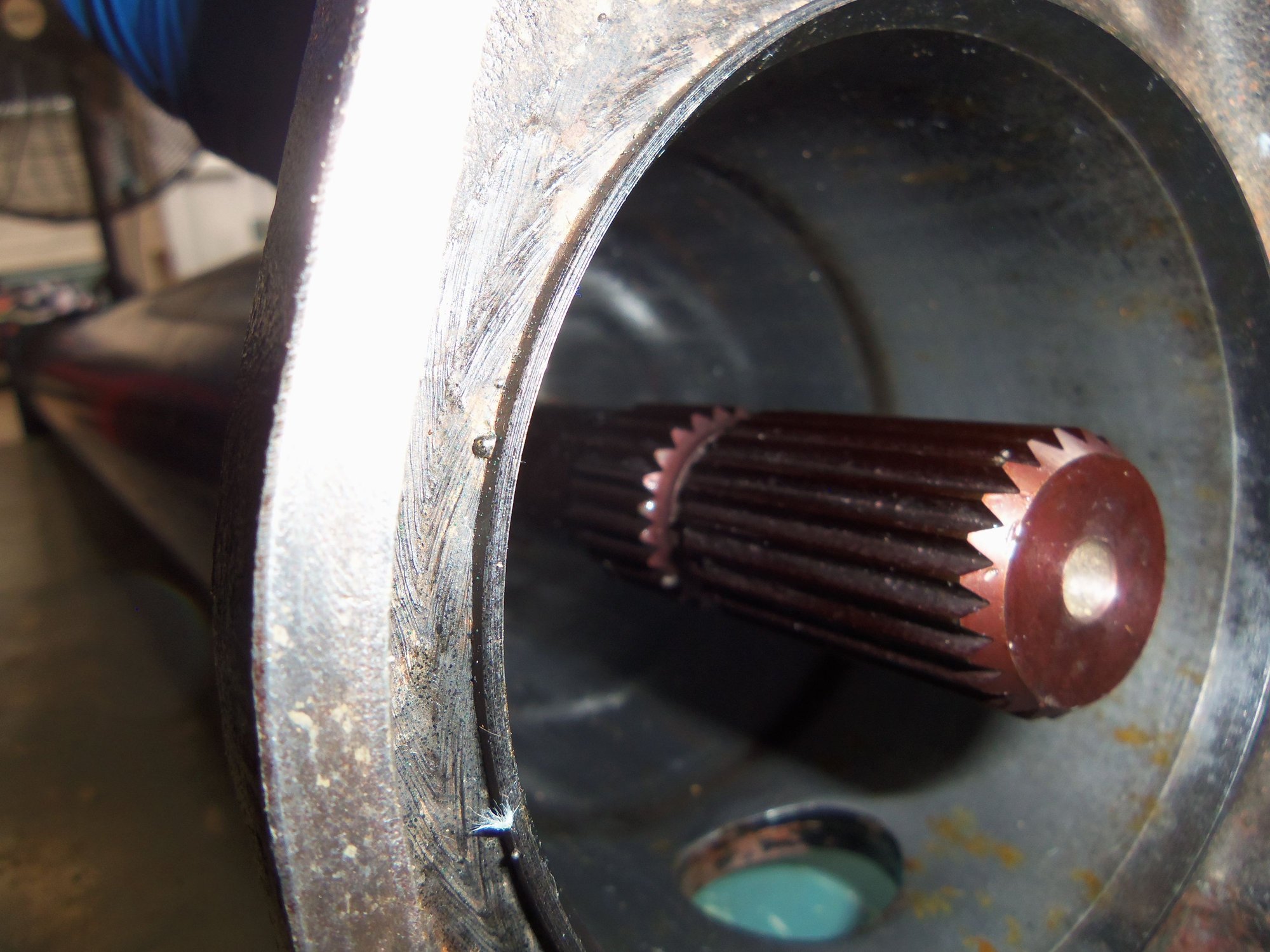
Transmission end of the drive shaft.
Transmission splines.
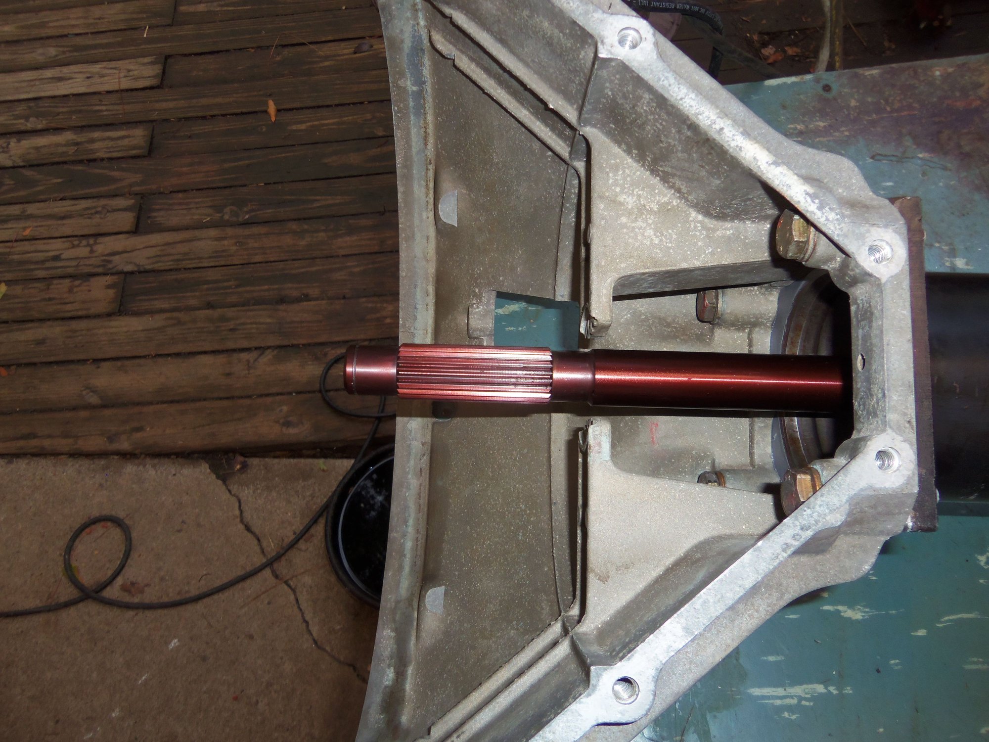
Engine end of the drive shaft.
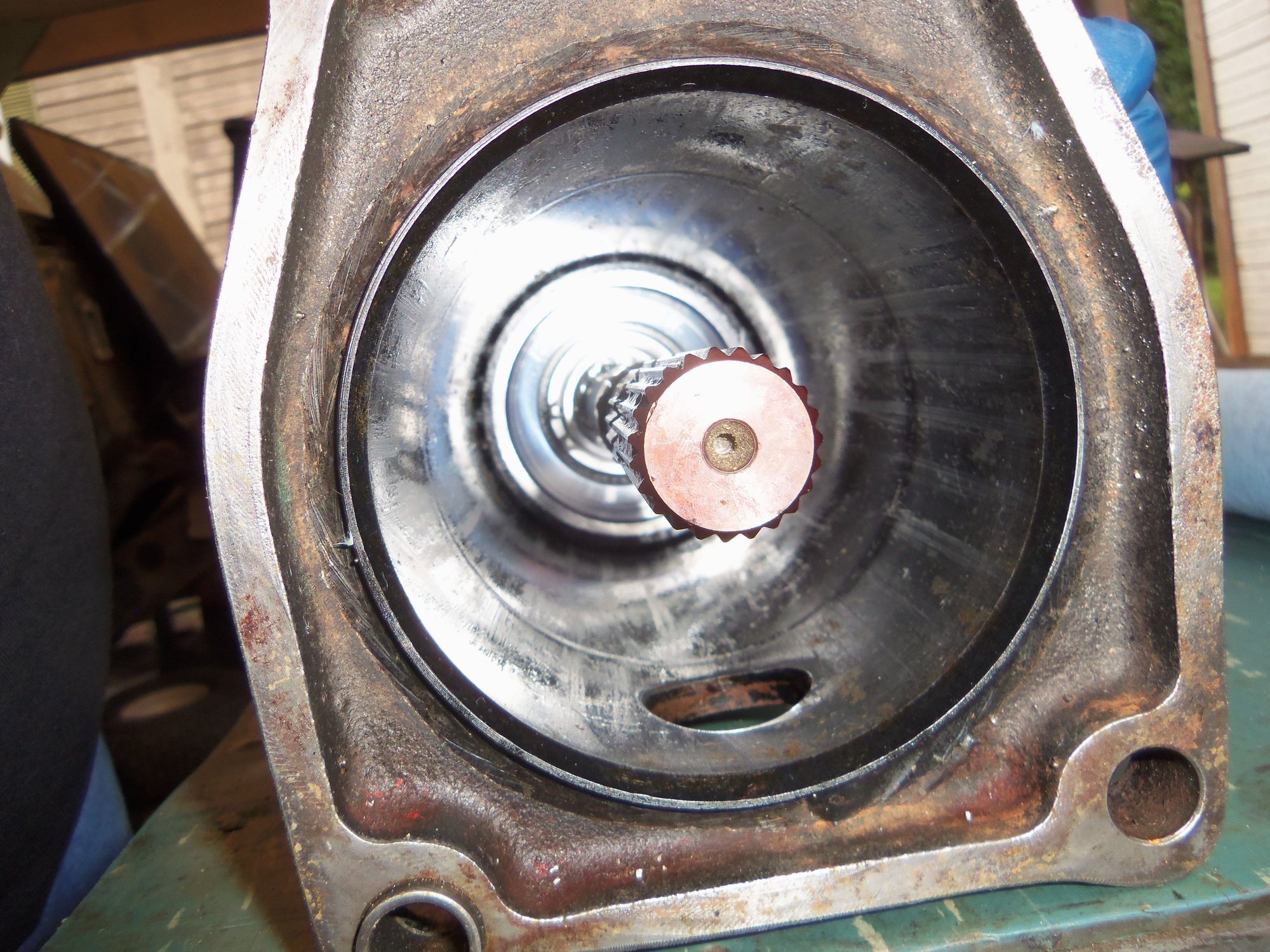
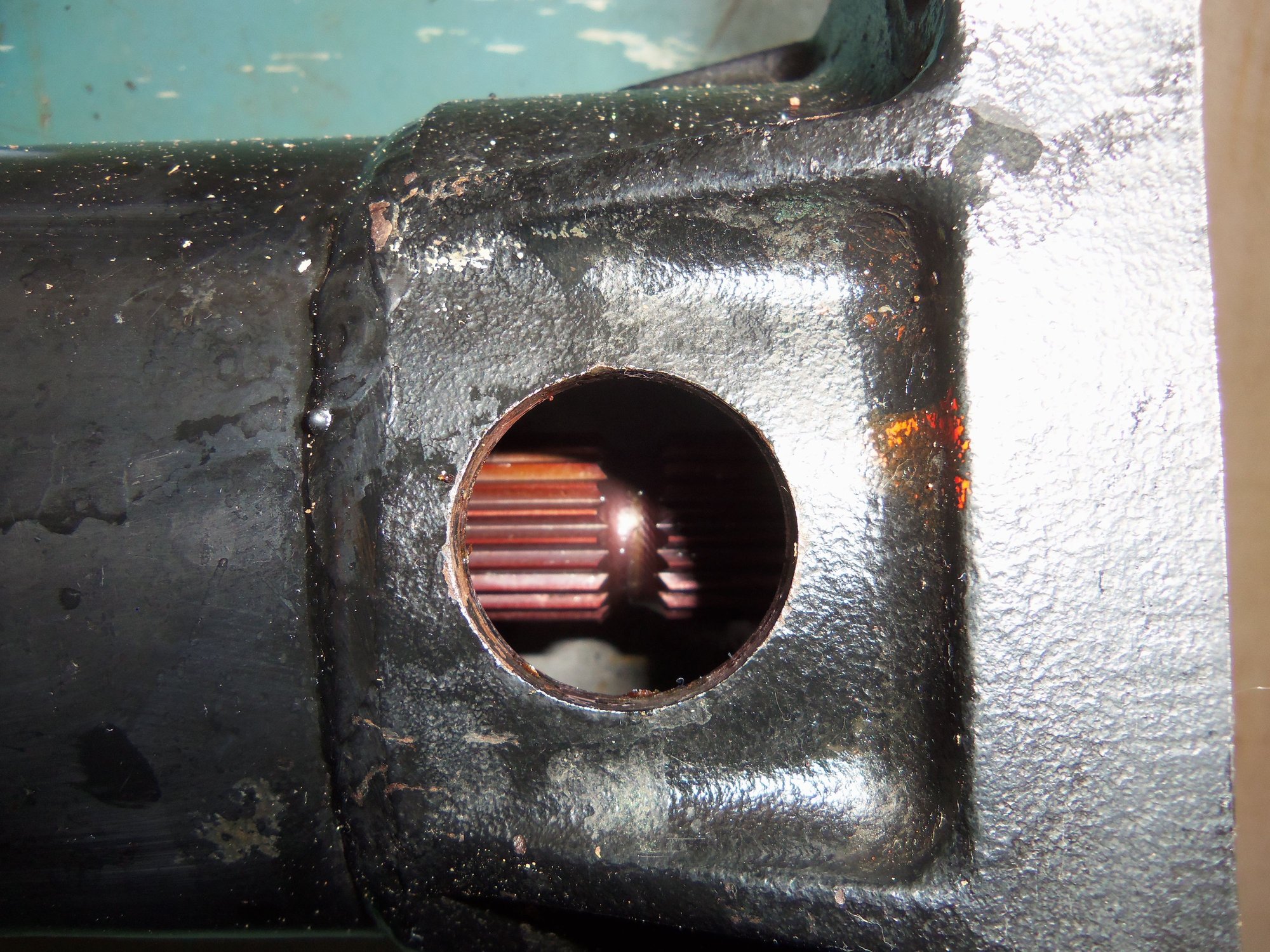
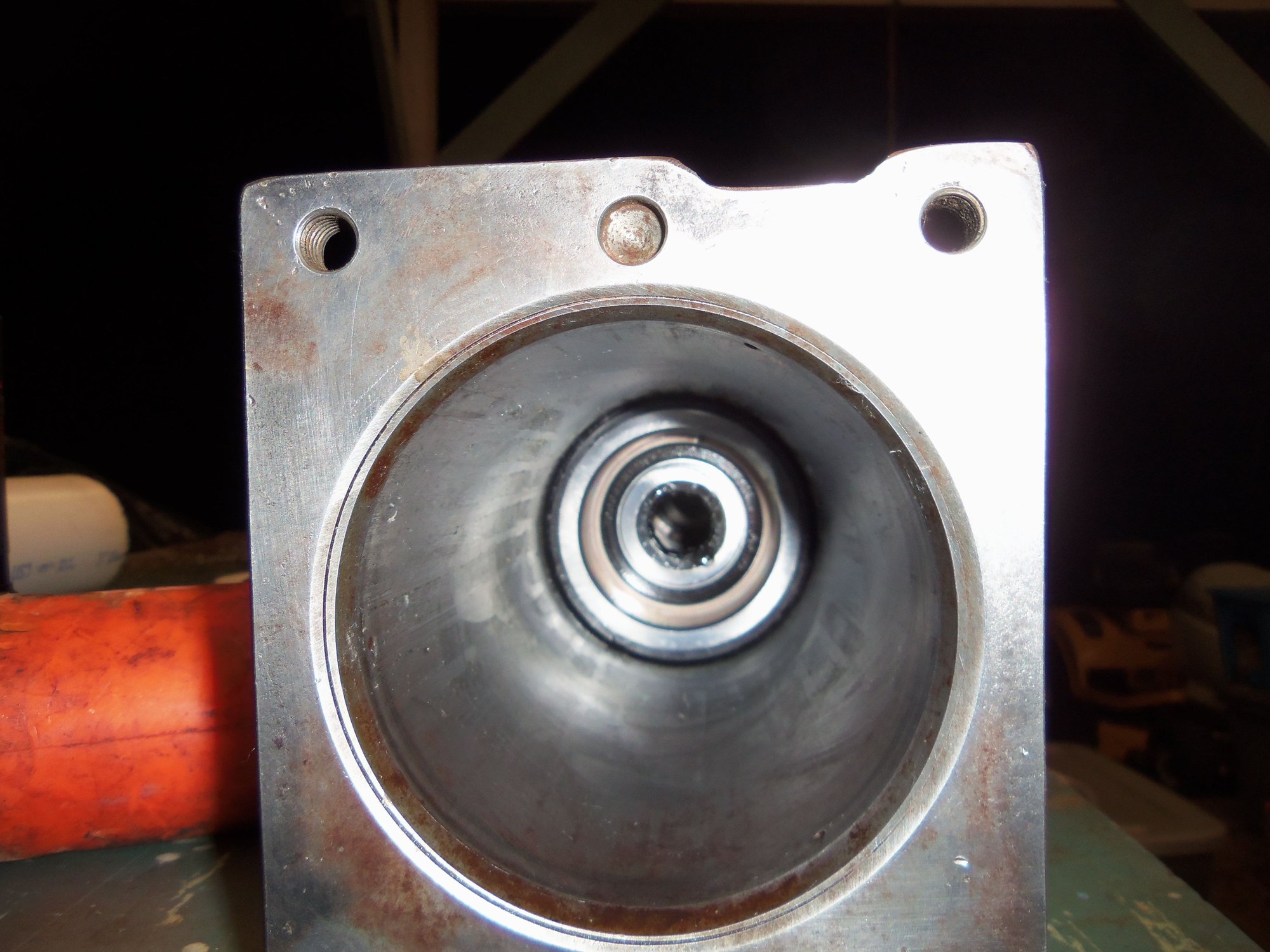
Looking at the drive shaft down the torque tube.
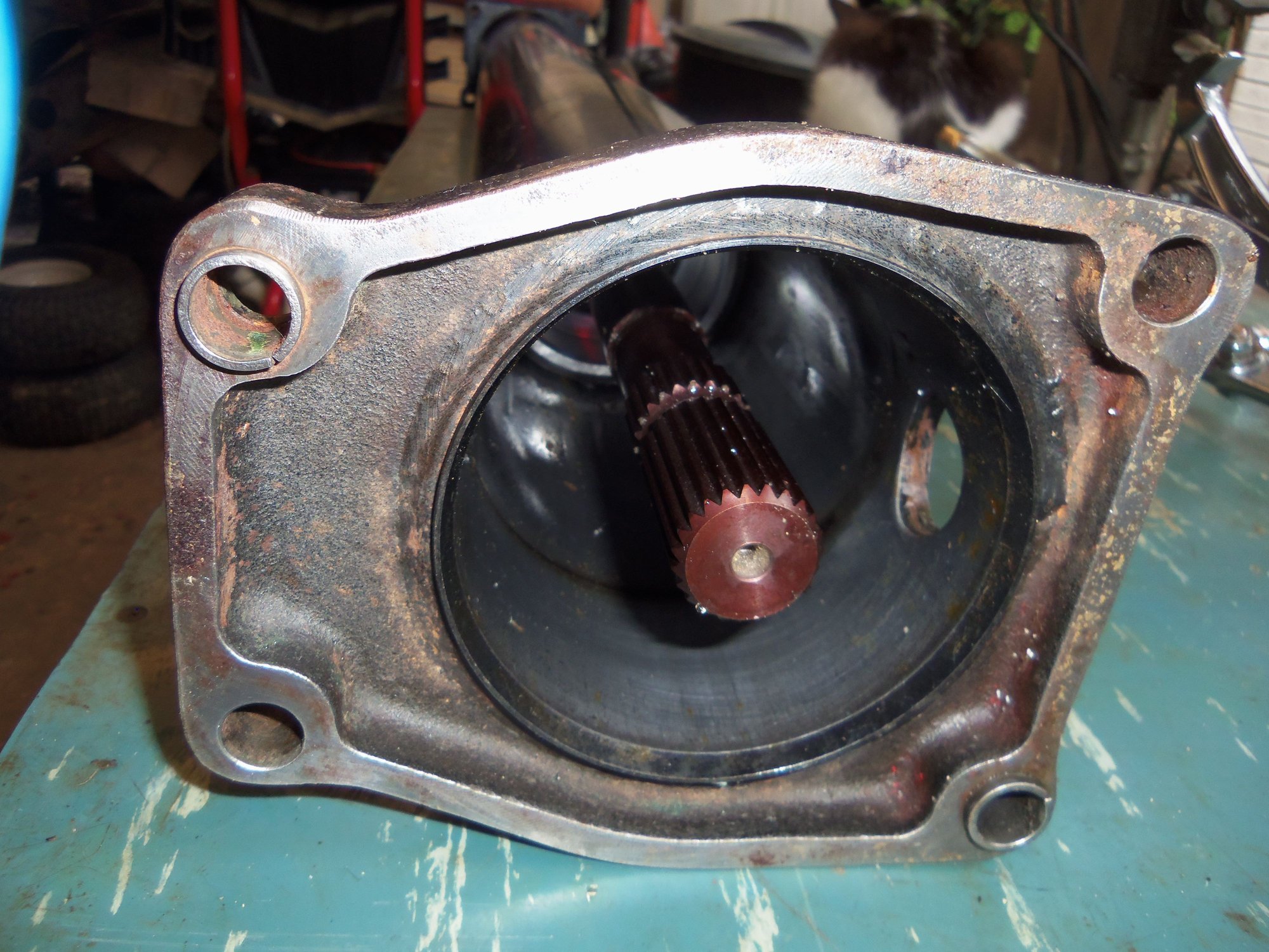
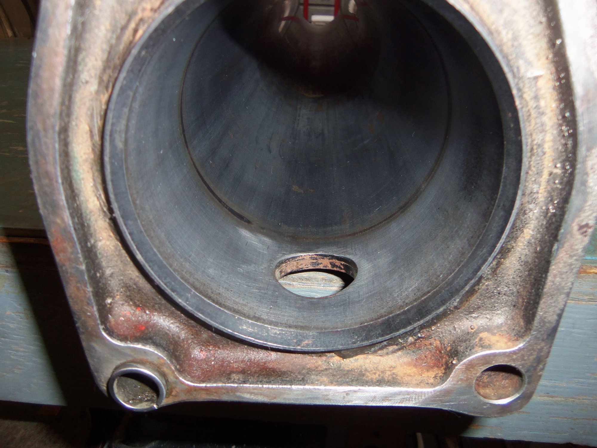
Cut out section of splines looking through the access hole at the transmission end of the torque tube.
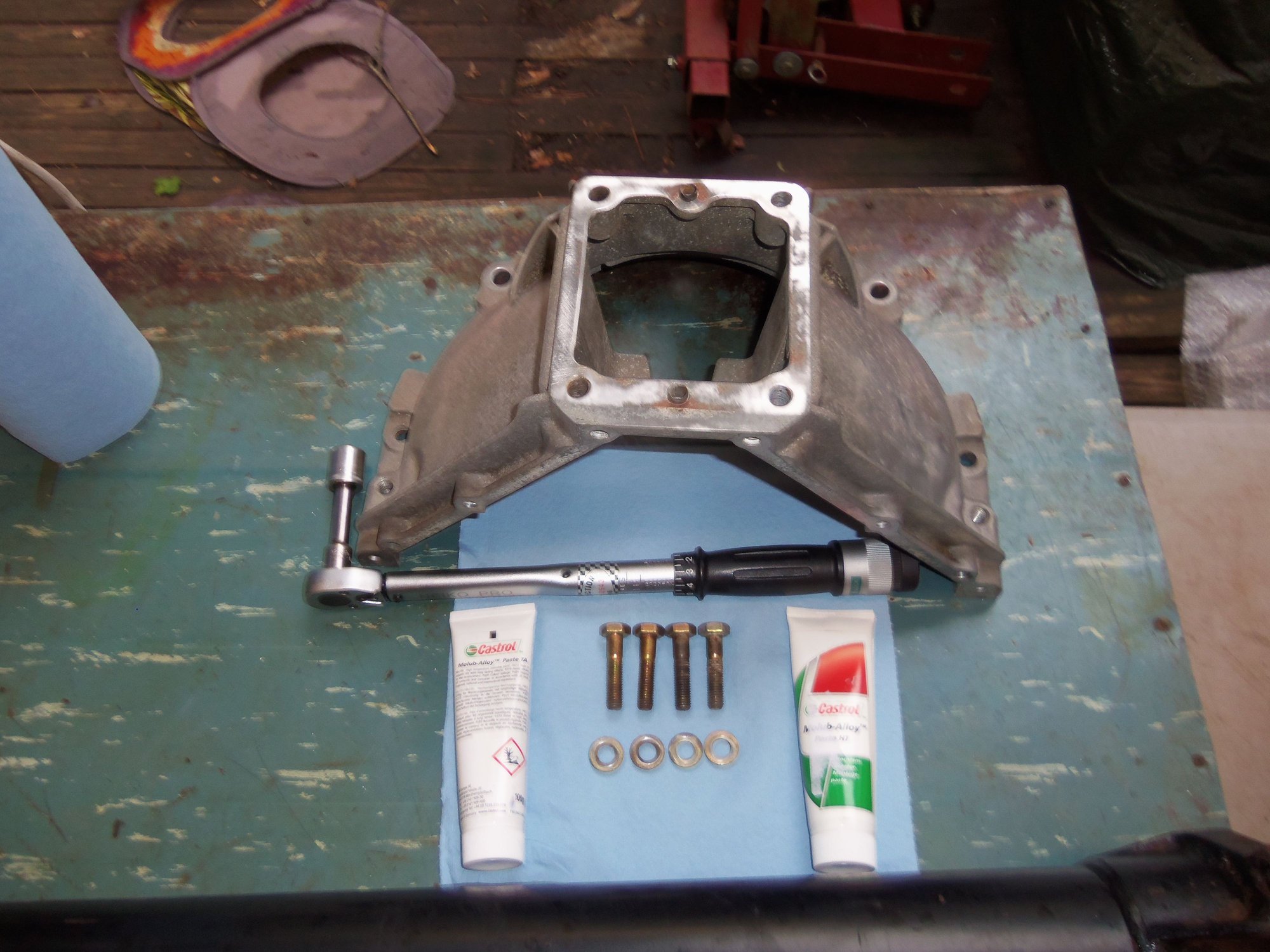
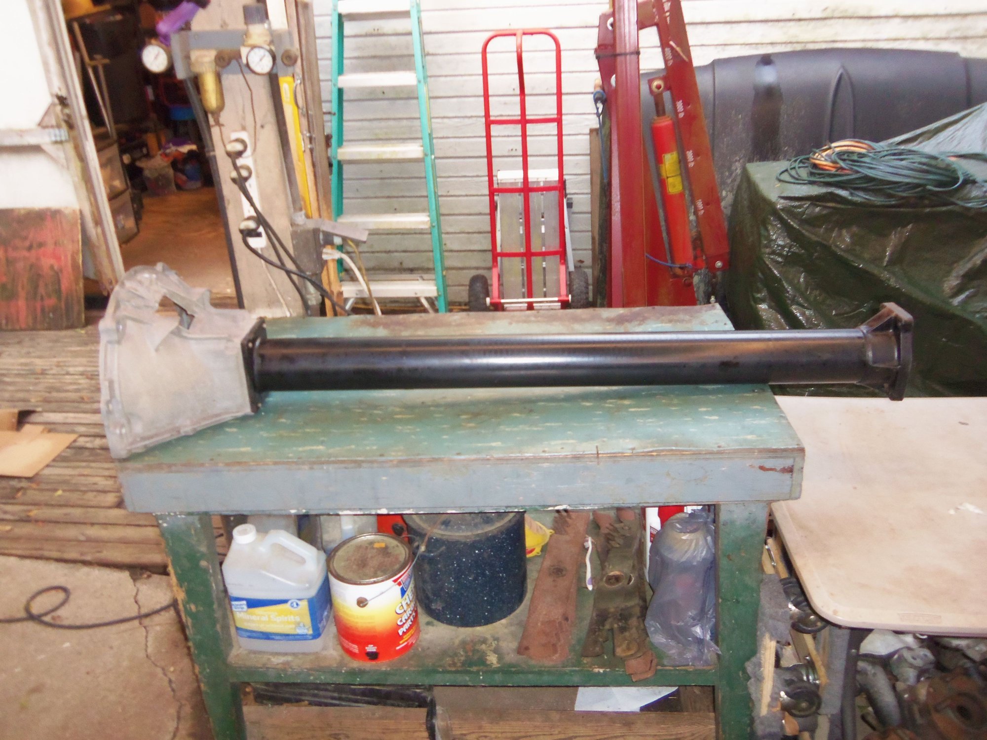
With the drive shaft finally in and in position, all that was left was to bolt on the bellhousing. I had already cleaned it and its hardware in the past.
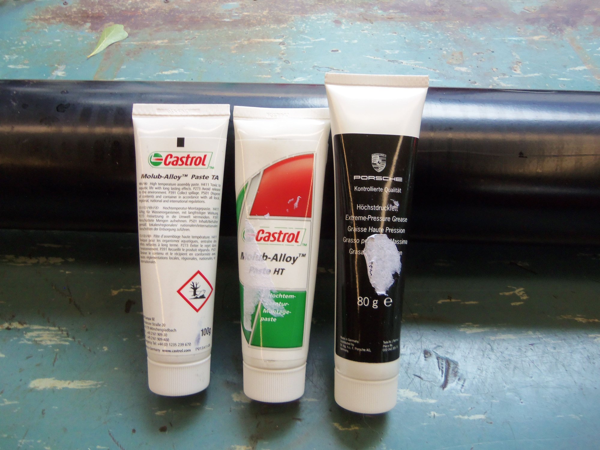
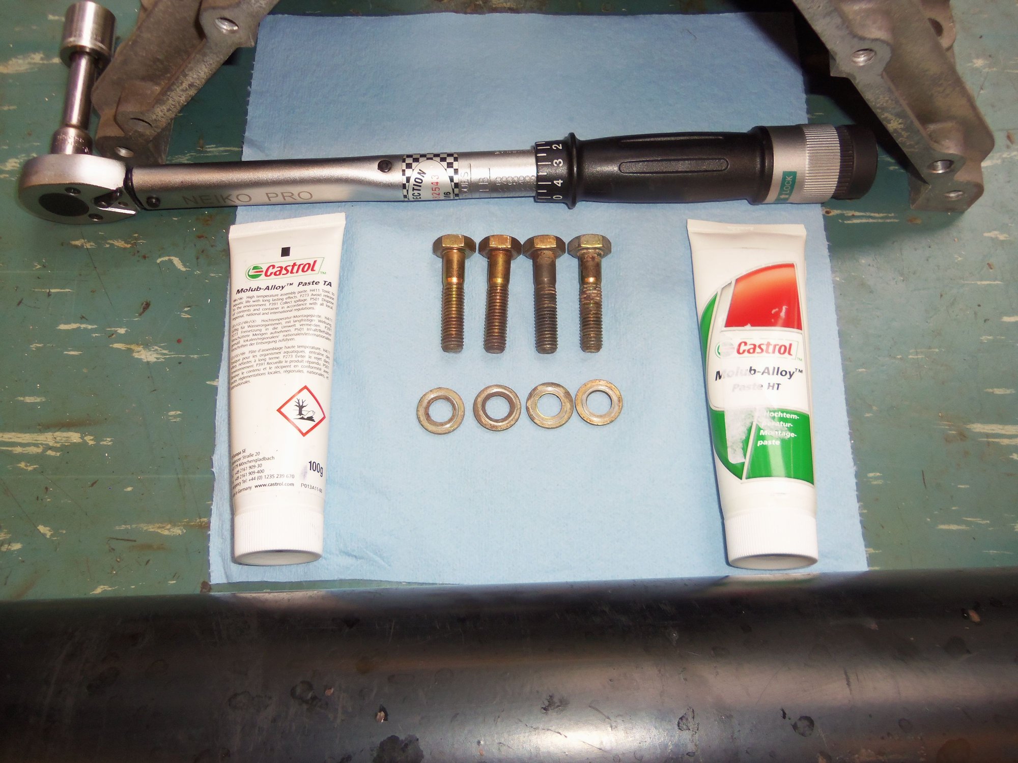
I finally ponied up and bought all the Porsche secret sauce lubricants: Optimoly TA, Optimoly HT, and High Pressure Grease. Because I have an automatic, I don't think I will need the grease, but it is good to have on hand. I guess I am getting a little numb. Those three lubricants were $100.00. That doesn't really bother me anymore...
The bolts that held the bellhousing to the torque tube had pinkish antiseize on them when removed. So, I put the gold Optimoly HT on them. I put a thin skim of silver Optimoly TA on the engine side flange of the torque tube for corrosion prevention. Installed the bellhousing, torqued the bolts to 45 Nm and called it good.
Finally bought all the Porsche secret sauce.
Bellhousing, some assembly required.
Silver Optimoly TA for corrosion prevention between the aluminum bellhousing and the steel torque tube, Gold Optimoly HT for the bellhousing bolts.


 02-20-2019 | 11:37 PM


 I am going to have to live with this. Short of completely disassembling the torque tube again (which isn't going to happen), I don't know of any way to pull the front bearing to the front. So be it. I think it will be OK.