When you click on links to various merchants on this site and make a purchase, this can result in this site earning a commission. Affiliate programs and affiliations include, but are not limited to, the eBay Partner Network.
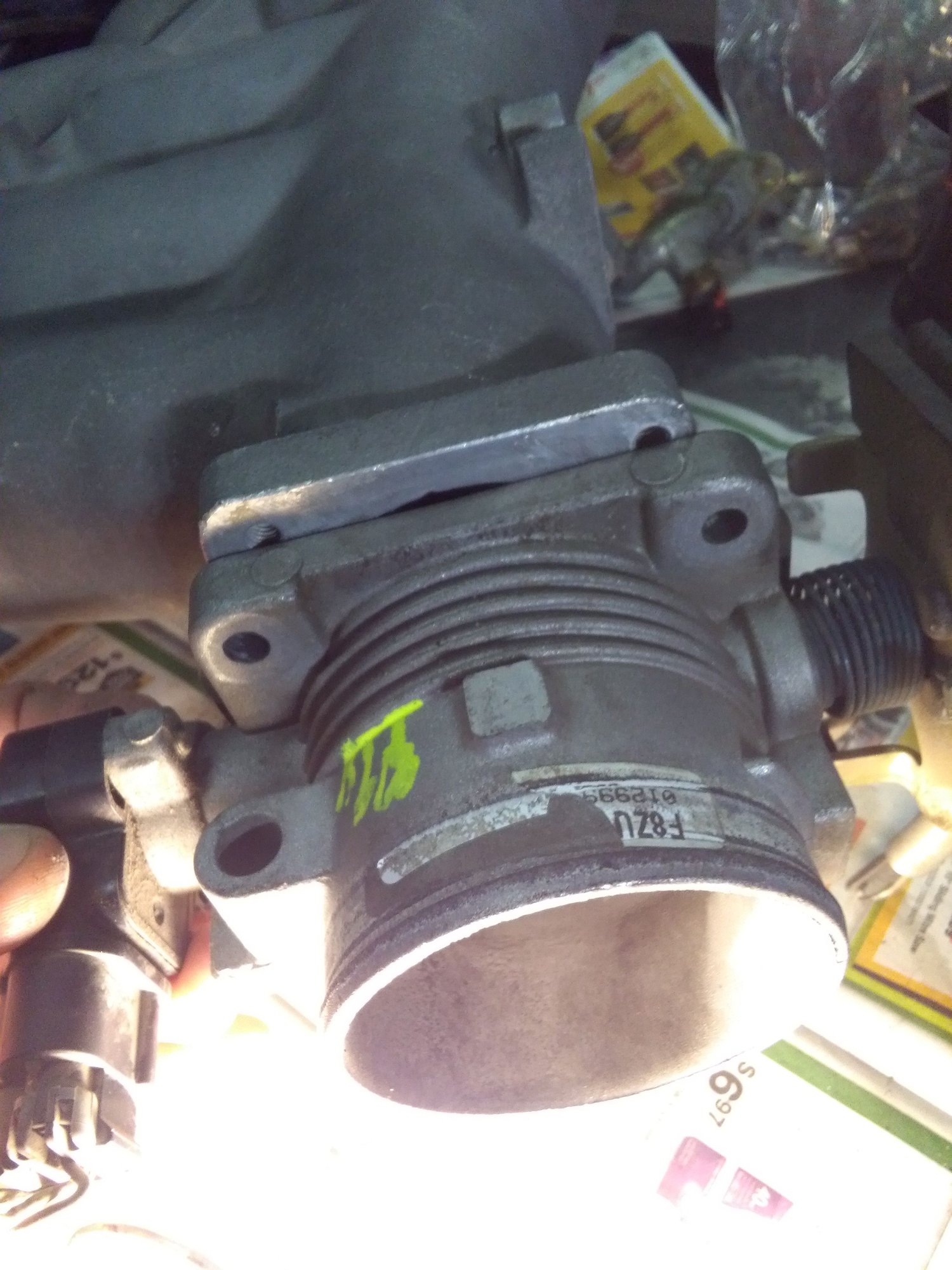
Bolt pattern of 951 is smaller in both height & width.
First thought was drill out 4 holes in Ford TB but it's going to look ghetto that way. I think the best is make an adapter pipe from thin wall exhaust. I wonder what other dudes are doing?
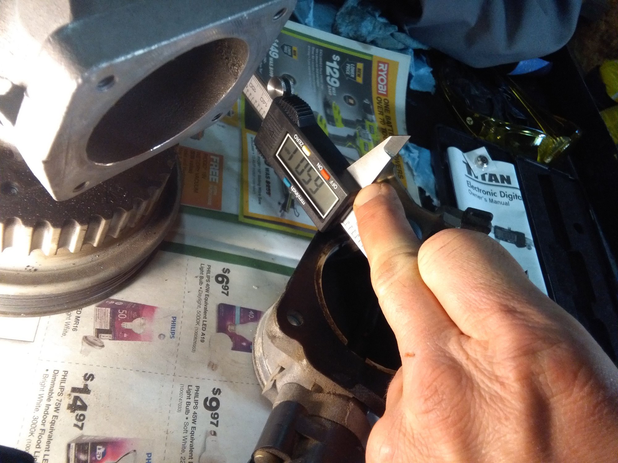
951 intake manifold measures 62mm and the mighty crown vic B measures 65mm.
I think I can bore them both to about 66mm.
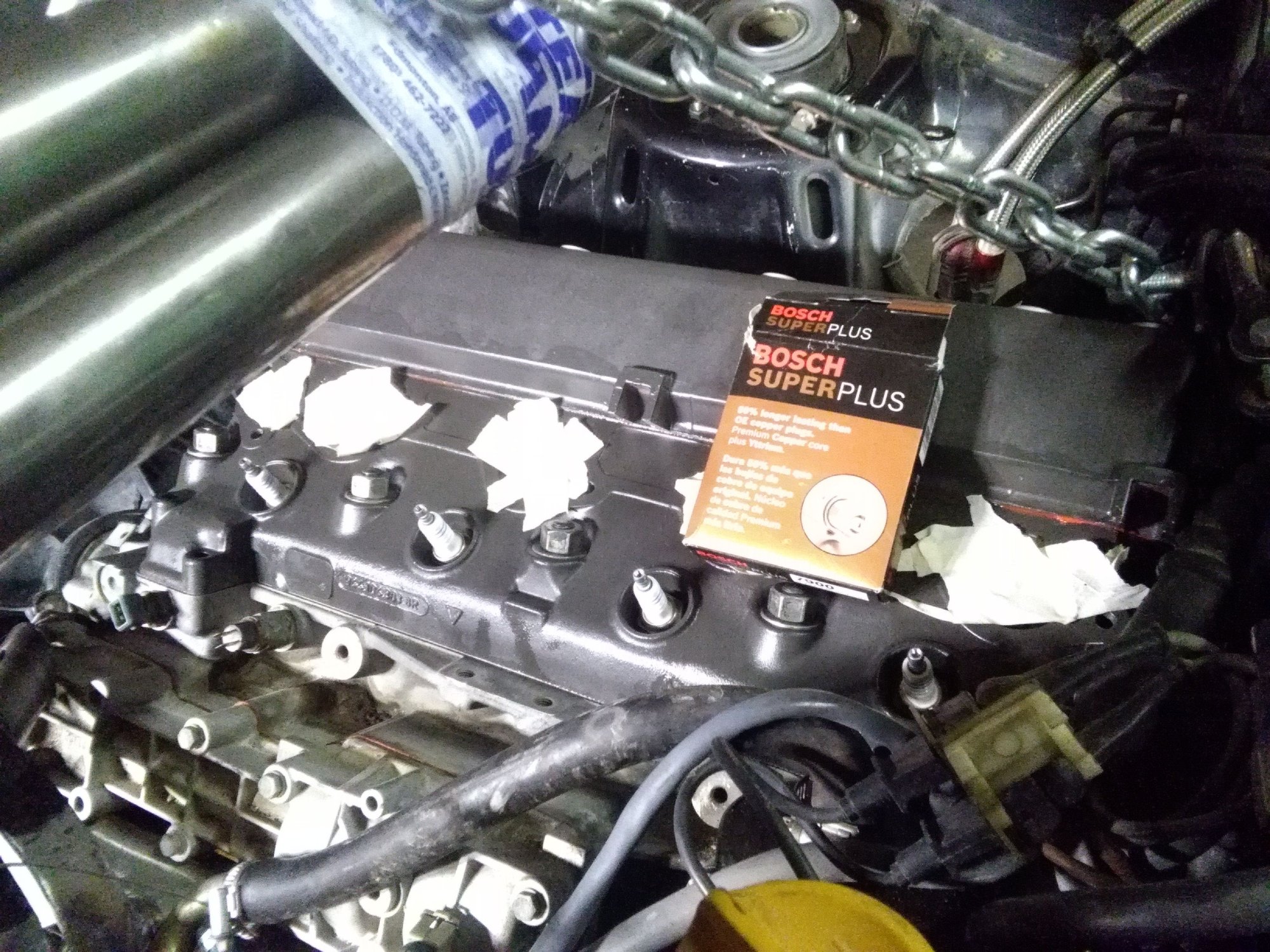
I need to install the oil pan & crossmember below so hanging the engine from the top. Plugged holes so no contamination. Changed spark plugs to these, as a lot of the big boost daddies seem to be running 'em. I noticed the gap is tight. Spark plugs are 6 times the price in Canada then USA. I had these ordered from when I was going to run Nitrous though.
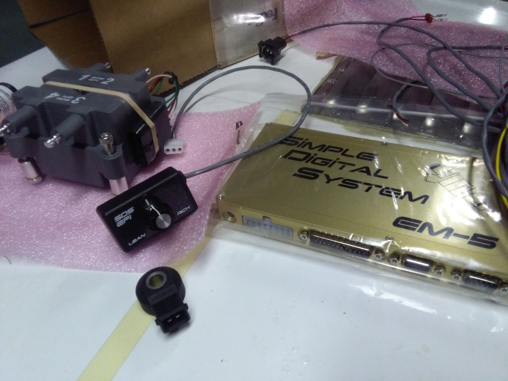
Engine management system ( EMS ).
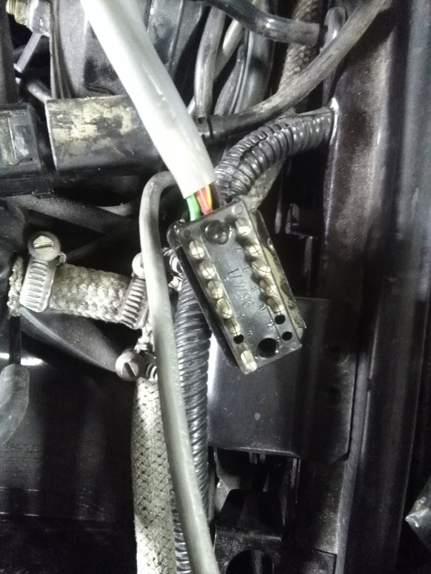
Starting to address the wiring & inputs/outputs.
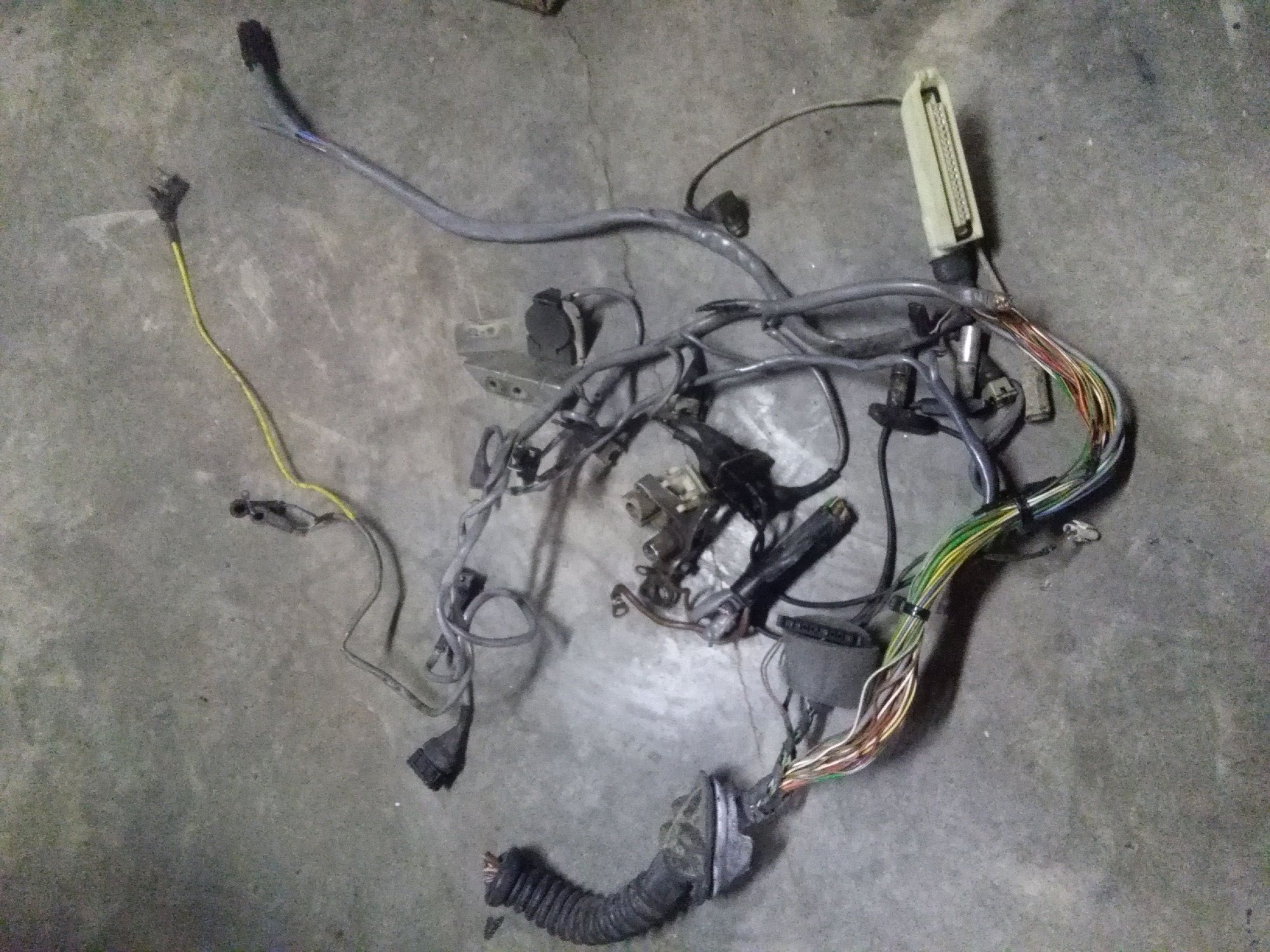
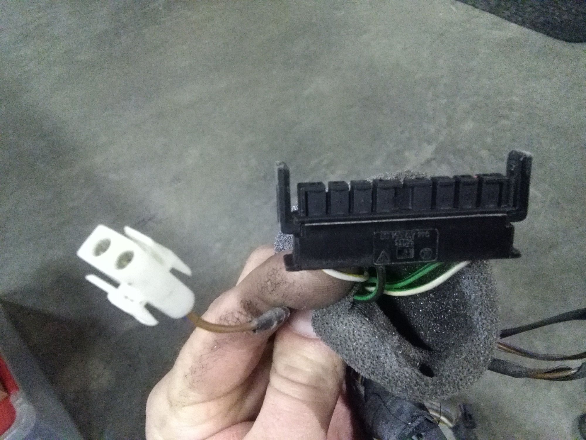
Started with removing the DME to engine harness (which unfortunately also ties into other systems.
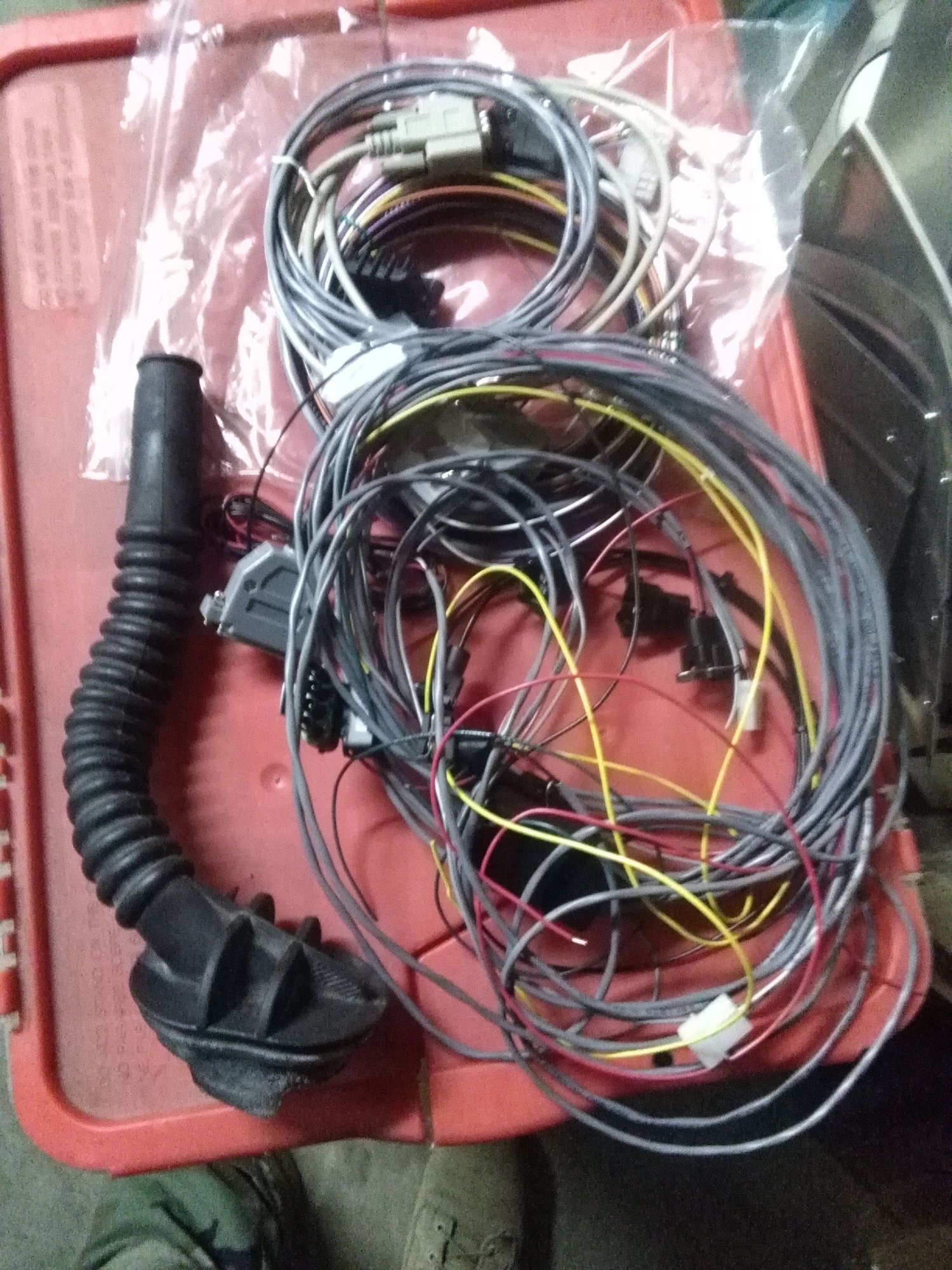
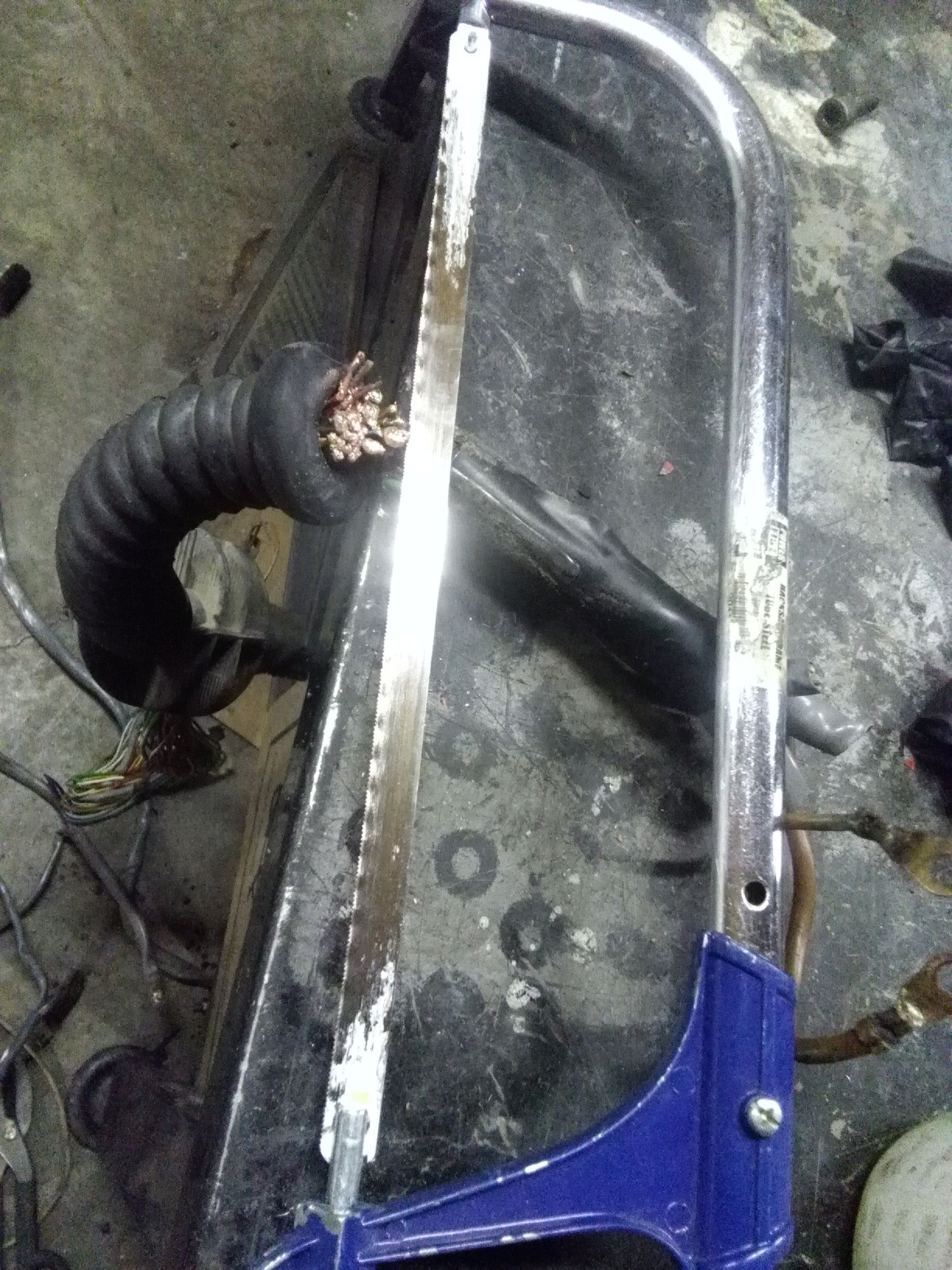
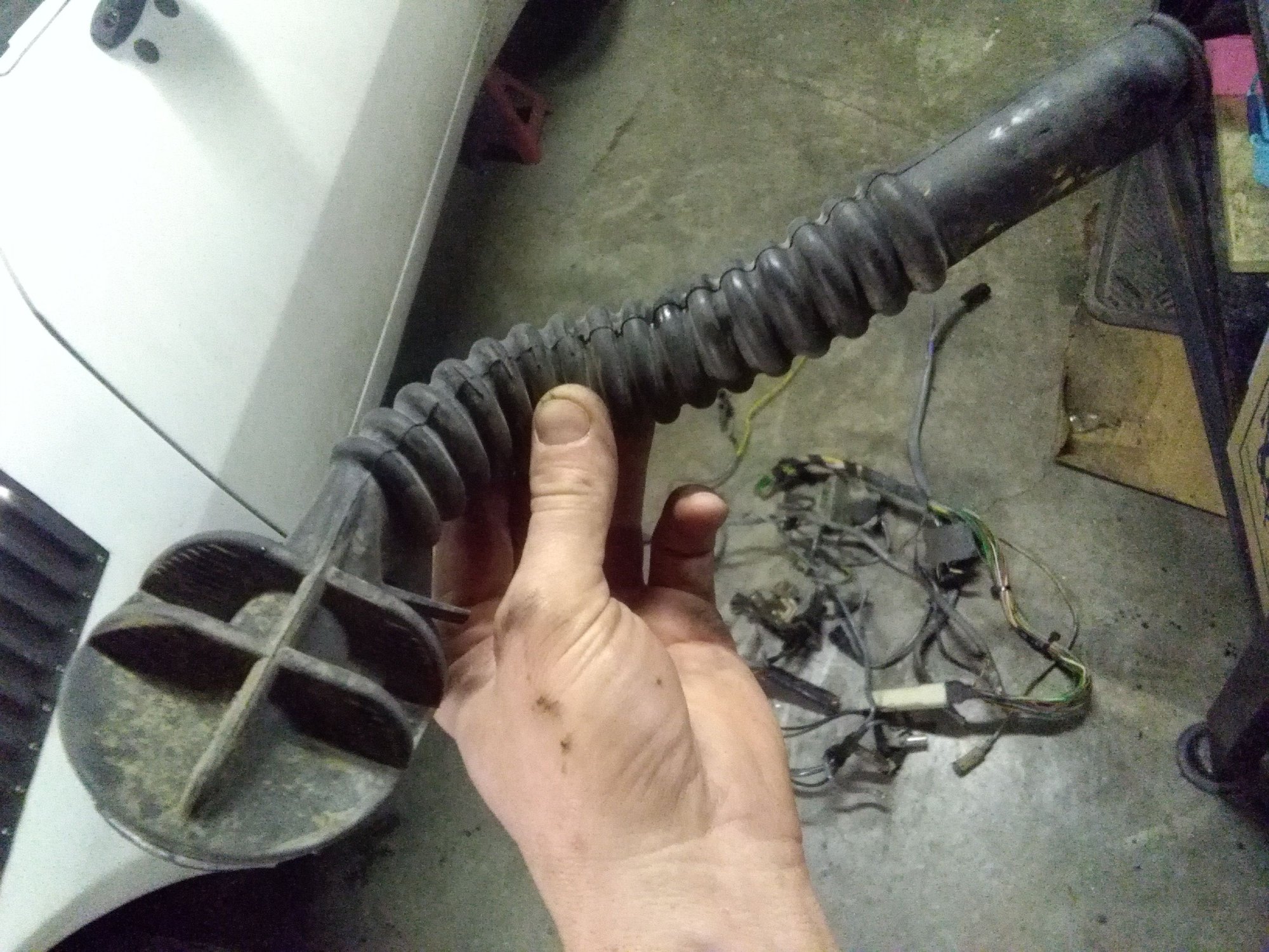
Fortunately the SMS EFI standalone has connectors off the terminals to easily slip through firewall. I will be using the oem rubber boot. Which wasn't easily removed. Felt bad about hacking parts off but thats what I did (because time constraints).
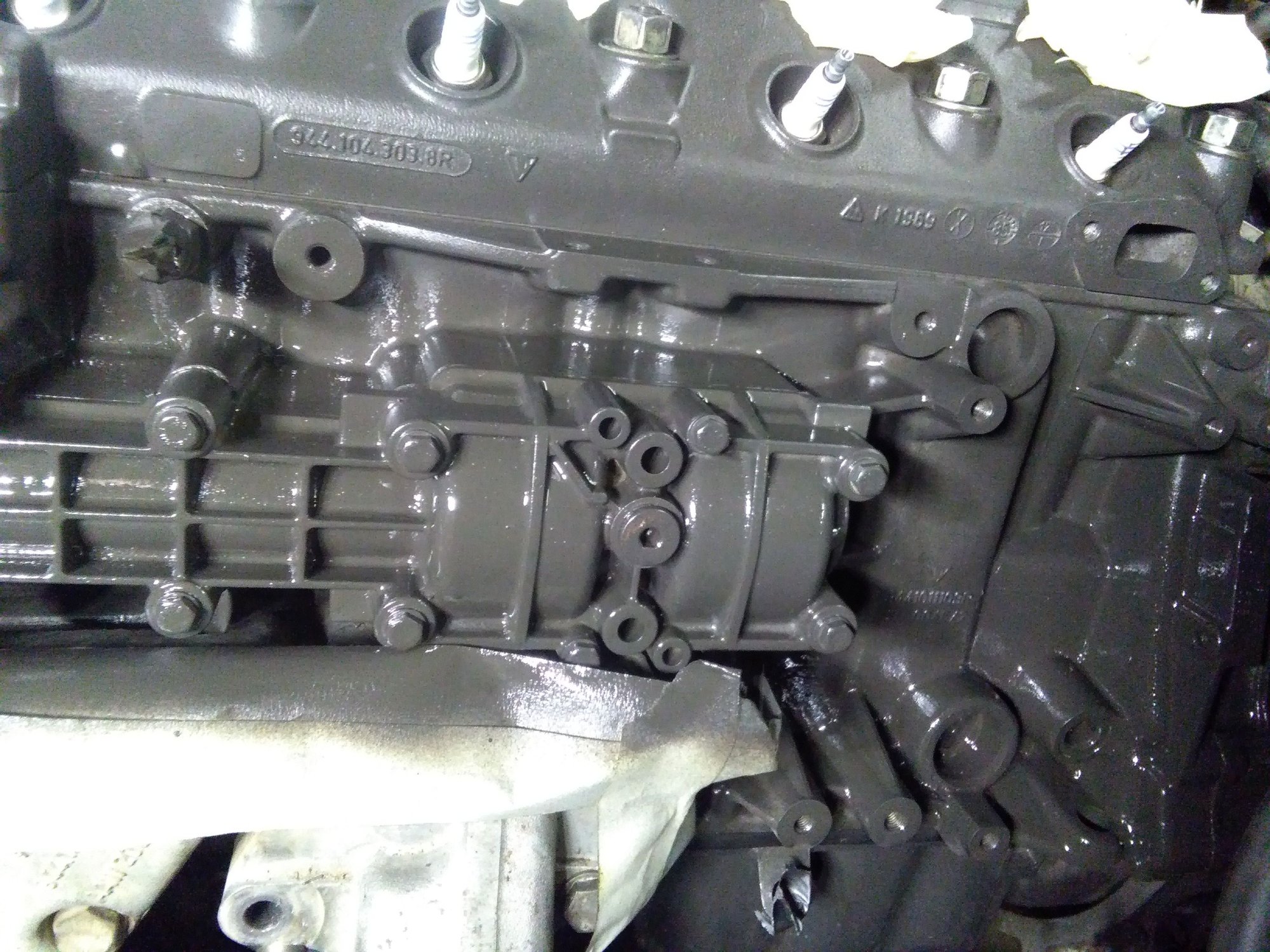
I won't get a better opportunity to clean & paint the back of the block, so took advantage.
I haven't looked at the wiring schematics yet.
I suspect they control Idle speed for loads such as a/c.
I suspect radiator fan is controlled through one of these. Maybe both rad fans are?
I suspect starter s-terminal to crank from ign switch goes through one of these.
I suspect inputs to dash gauges are also?
Please share info if you know! Just a guess but I don't think I can cut all these wires out & install the SDS system & have my heater/ac, starter, fans & all the gauges work. Surely I need to open up part of the harness I removed & sort that other stuff out. Agreed? This is an 88 n/a 2.5 car.
geez Michael, I knew I could count on you and you totally came through brother!!
Lemme know about joint purchase of the starter ring gear for your cars application.
I was very impressed by your packaging, but have not looked in the parcel because it's in my wife's car trunk. And I'm running out of room. THANK YOU. I CAN'T WAIT TO HAVE A BIG OL CLUTCH in 951 bellhousing. I don't know if I will install it sooner or later. Spring is here & I still have to do so much above & beyond engine stuff that I think I will hold off and just rock some low boost for 2017.
----
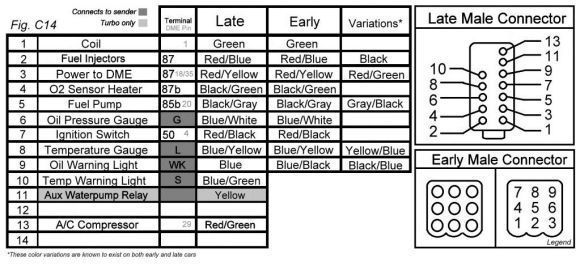
That connector chart is the ****. Where'd you get it? Appears to be inputs & outputs? I will lean heavily to your electrical & tuning knowledge over the next few chapters.
Was planning on loosely routing the engine electrical through the rubber harness boot & into the engine bay... but decided it's too early at this point because there are more pressing mechanicals to fit and account for.
A quick scan over the SDS EFI system allowed me to have clarity that any "serial" type connectors go to the interior of the car (where the programmer & ecm & fuel tuning dial are) and the other weather pack connectors & such will be in the engine bay. So, no problems that stuff was designed to fit through firewall grommets & was designed to be easy-peasy.
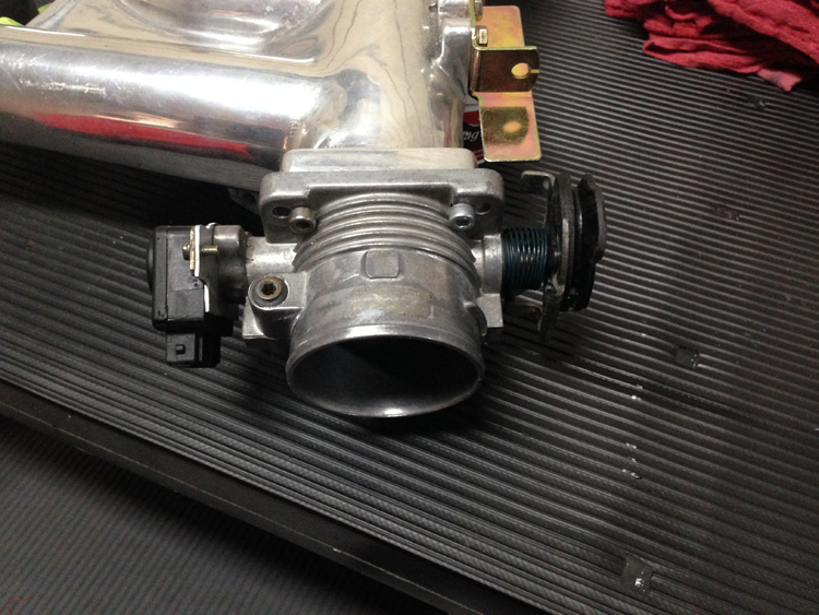
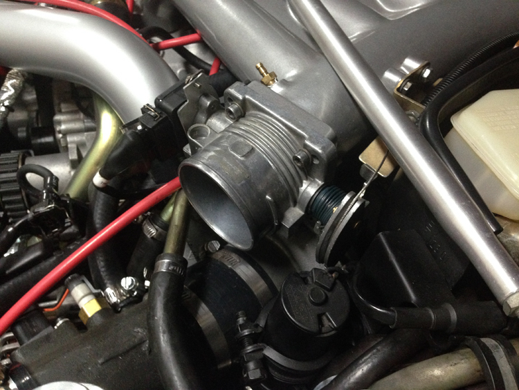
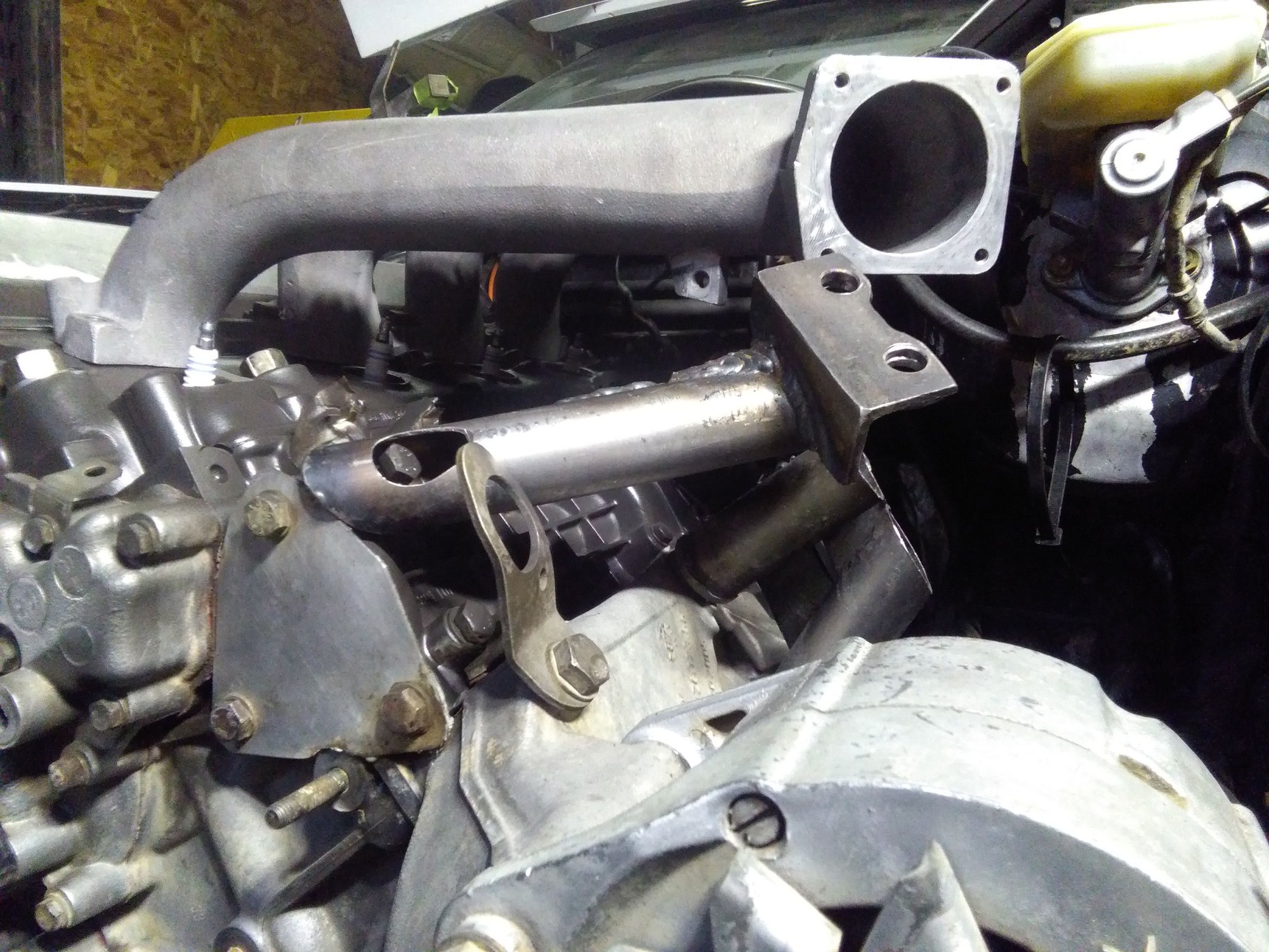
Bolted up the 951 intake mani. Super pleased with how "proud" (brit term); how high it sits compared to the n/a mani. Obviously it was higher to account for turbo to fit underneath. I really like the extra access room to temp sensors & whatnot underneath, which is normally super tight fitting on the n/a system.
But as you can see the turbo mount I made is a no-go with 951 intake manifold.
So, I need to decide, compromise & stick with the n/a manifold or put in the turbo manifold? The main hesitation is the exhaust in & out pipes I built onto the turbo flanges will need modding. Particularly the turbo in (the exhaust which spins the turbo up). In a nut shell, this turbo design is NOT IDEAL for what I'm trying to accomplish.
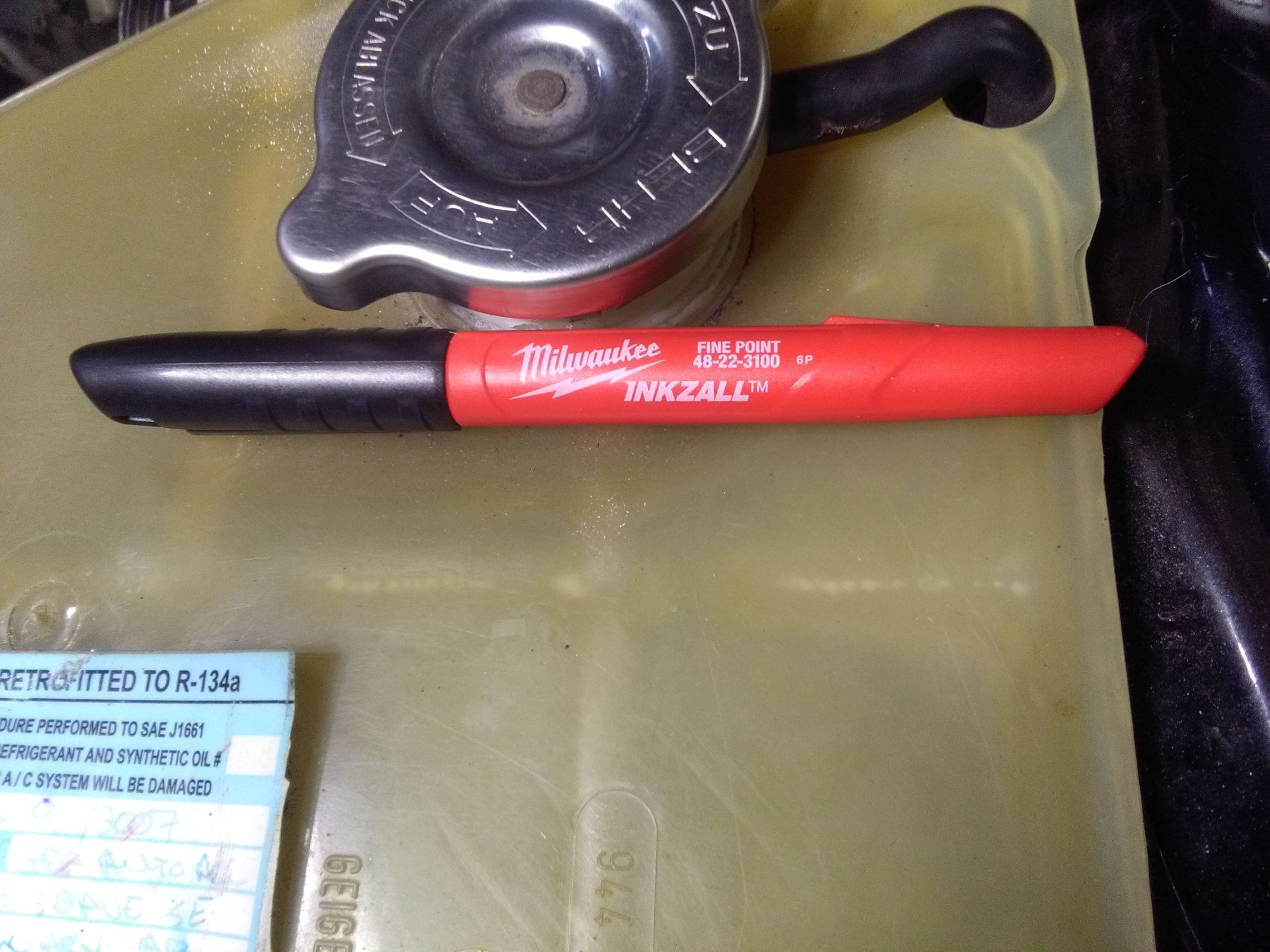
On the bright side, all my Sharpie pens are pretty worn out. And I have it on good authority that THESE pens are the Best. Now I'm armed and dangerous with a 5 pack from Home Depot. Ready to fabricate... somethin'.
If I learn nothing else from you brother, at least I now know INKZALL is the pen of choice!
Your progress astounds me Noah. But I thought you hated computers, and now your going stand alone? I'm so interested to see how it goes once you start that leg of the journey.
I keep having this voice in the back of my head (strangely kinda sounds like Michael, even thought we've never talked except on here) that keeps whispering MAF and mega squirt or at least rouge from LR. I can't wait to see how yours works out!
In the end, I think I'm going to stay mostly stock aside from maybe a chip and some shims. But I've got to get all the little stuff in order before I even mess with any of that!
That connector chart is the ****. Where'd you get it? Appears to be inputs & outputs? I will lean heavily to your electrical & tuning knowledge over the next few chapters.
Glad it arrived ok. As far as the chart, a guy who goes by "edredas" on 924board made it, it was invaluable for my ECU setup. I recommend cutting off the plug from a spare harness and making it a part of your new harness, so it can just plug in without modifying the wiring going to the fuse box and battery.
In short, there are a few wires you need to find in your SDS harness:
+12v to power the ECU --> pin 3 on chart
Fuel pump activation wire --> pin 5 on chart (note: check your SDS manual to make sure that the fuel pump wire provides a GROUND when it wants to activate the fuel pump. This will activate the fuel pump side of the DME relay)
Optional if you have AC. You can connect Pin 13 on the chart to a spare input on the ECU, and when the AC is the ECU will be aware (you have to set this up in the tuning software). Then you can set it to idle a little richer / advance timing at idle, so the drag from the compressor is compensated for.
The following do not talk to the ECU but you need to wire them like this:
Pin 2 on chart --> connect to all 4 injectors (common power). Just pick 1 of the 2 pins on each injector, it doesn't matter which one since an injector is a solenoid. I recommend getting new 2-pin AMP connector, they are generic EV1 style and you can get them on ebay, amazon, mouser etc for cheap. Plus the new ones usually have a thumb-depressed clip for quicker removal.
Pins 6, 8, 9, 10 --> these connect to sensors and output their readings on your gauges. All you need to do is "complete the circuit" by running wires between the pins mentioned, and their respective sensor terminal. On the oil pressure and temp sensors, these should be marked L, K, WS, etc if you look closely. you can use the listed wire colors as a check to make sure everything is going to the right place.
Pin 4 on chart --> hopefully you are getting a wideband. You can use this to power the wideband, or you can use it to power other low current devices (do not use it for the coil pack) and power the wideband from a different 12v source.
Sort of like the O2 sensor power pin above, this can power stuff but it's best not to use it for high current draw. What I would recommend is that you use it to activate a relay. Get a basic 30A relay and wire this pin to term. 85 on the relay. Ground terminal 86 somewhere that's far away from the main bellhousing-area grounds. Terminal 30 can go to your battery +, and then terminal 30 on the relay can be the power to your coil pack. Use 10 or 12 AWG wire for those 2. That way it's powered when the key is on, and it won't tax the ignition switch.
Pin 1 --> this one is tricky. Just leave it disconnected for now, it's a pulsed ground for the coil and the only potential use for it is back-feeding a tach signal to the cluster.
Originally Posted by 951Dreams
I keep having this voice in the back of my head (strangely kinda sounds like Michael, even thought we've never talked except on here) that keeps whispering MAF and mega squirt or at least rouge from LR. I can't wait to see how yours works out!
I just googled an image... have been very curious on what "they" did.
-Not disappointed. HOLY CRAP. Porsche appears to have a 951 lhs engine mount with built in oil drain??? Looks crazy cool. Did they ONLY mount the turbo with the 2 oil drain screws?
I doubt it would work for me since I have a different turbo brother. Should I have bought a 944 turbo TURBO? Probably not with my budget...
I have what I have. Some research shows a reverse config for some of these turbos. Like the snail shell is reversed to what I have. I think that would be better. This one seems more appropriate for "hot side" engine mounting.
I sure wish I had an aluminum welder at home, then I could make some better things.
Anyway, I love the compactness of the 951 mount. So slick.
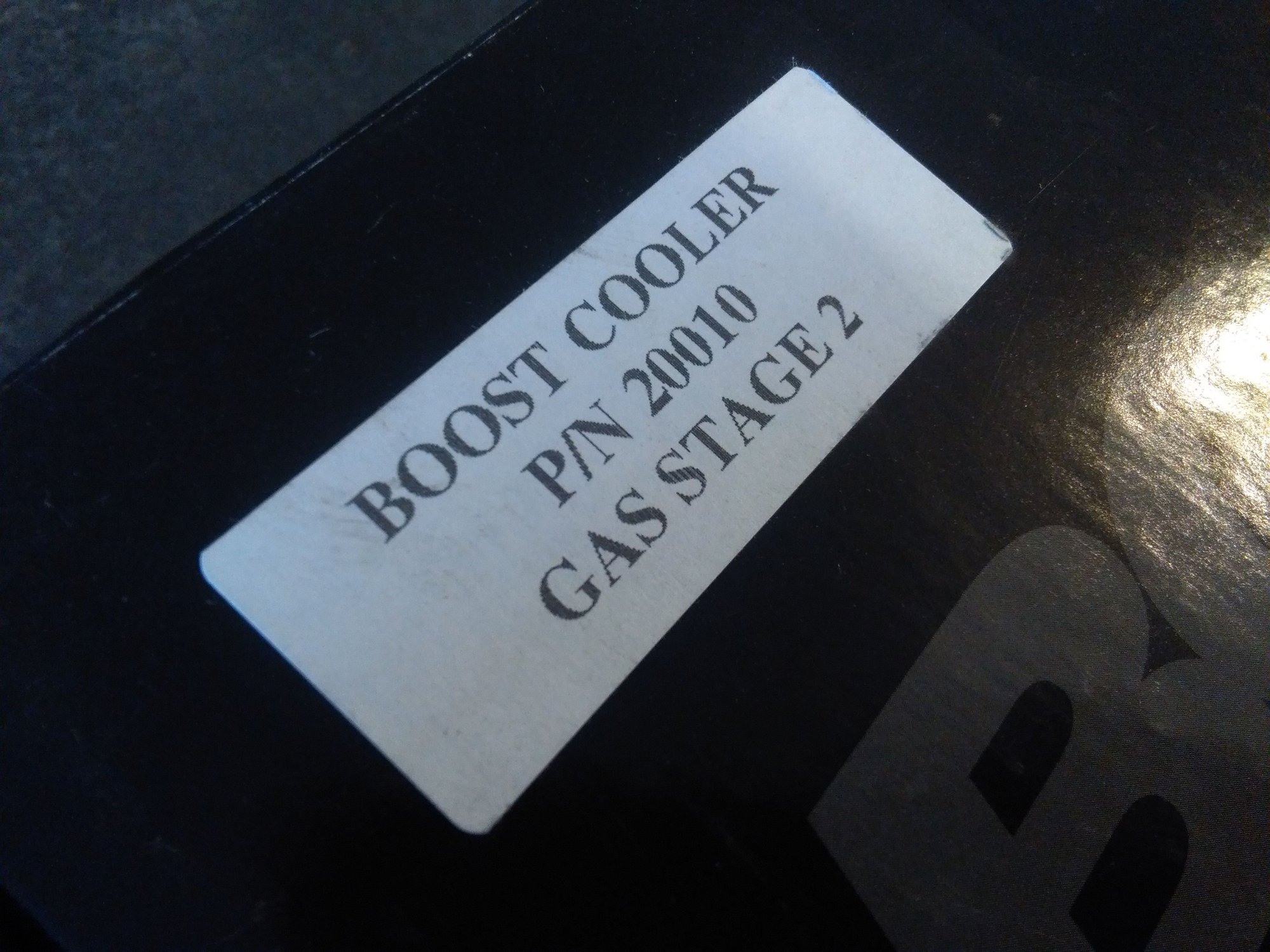
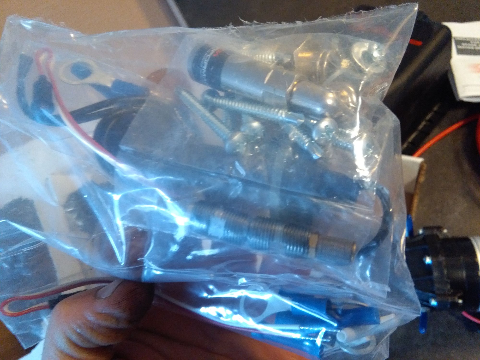
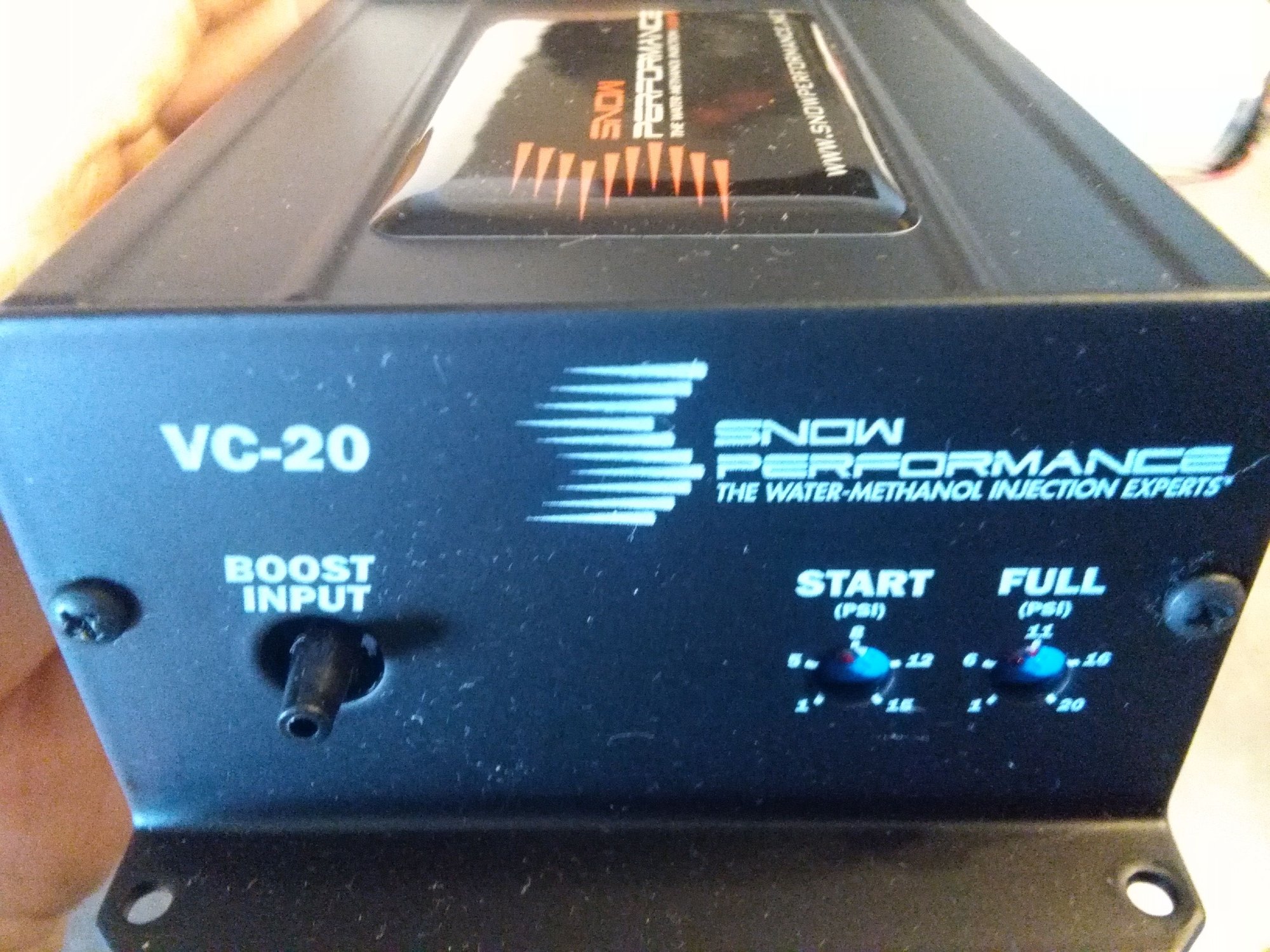
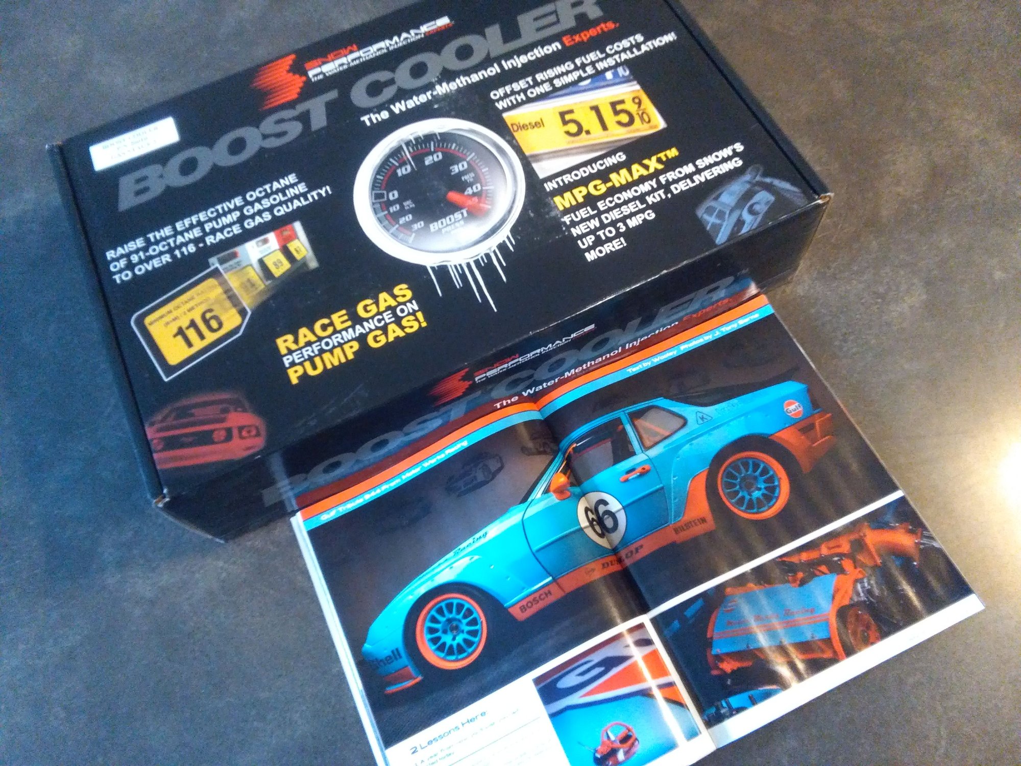
Guess what arrived!
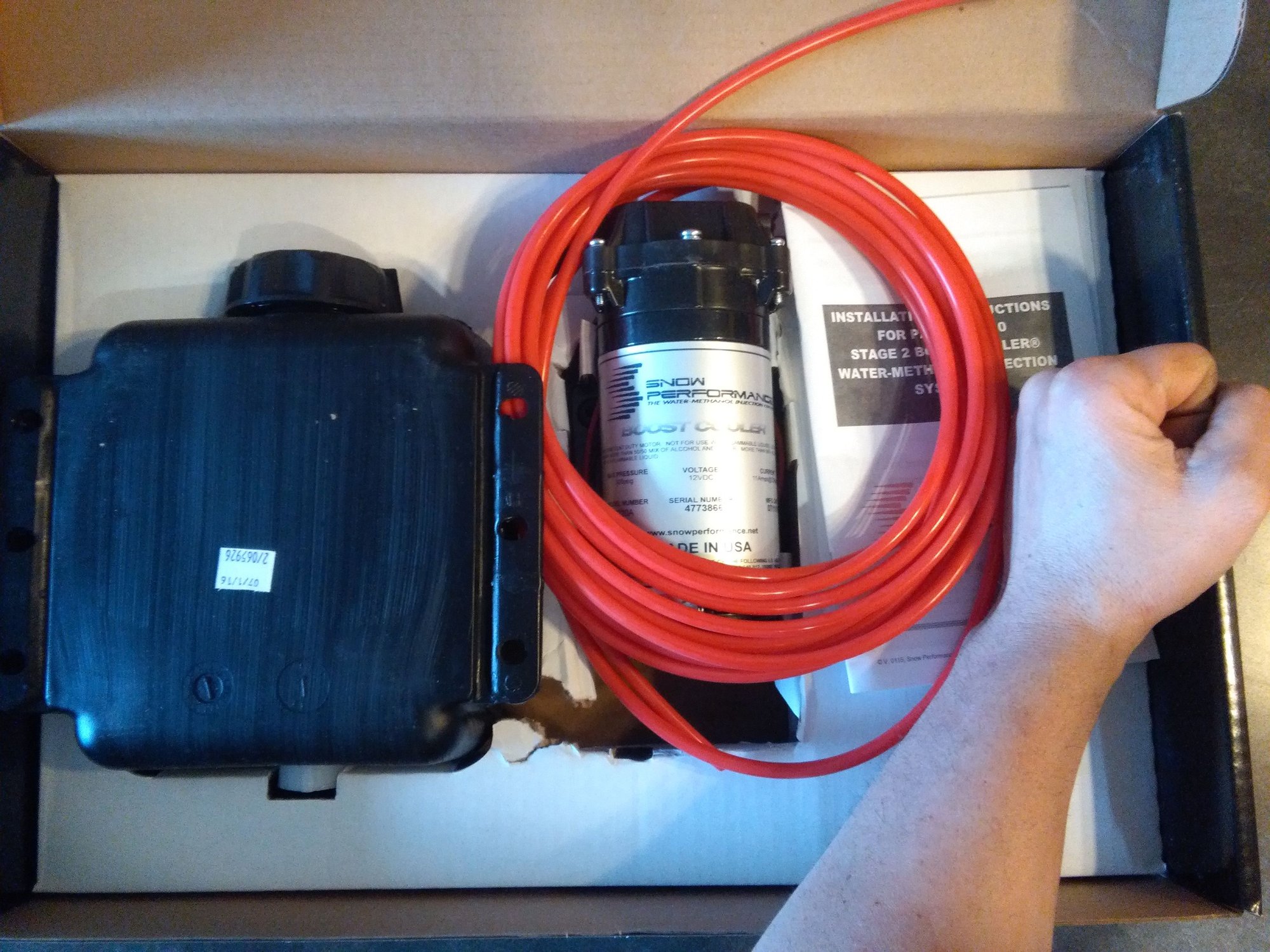
Unboxing of the Snow kit. This appears very high end.
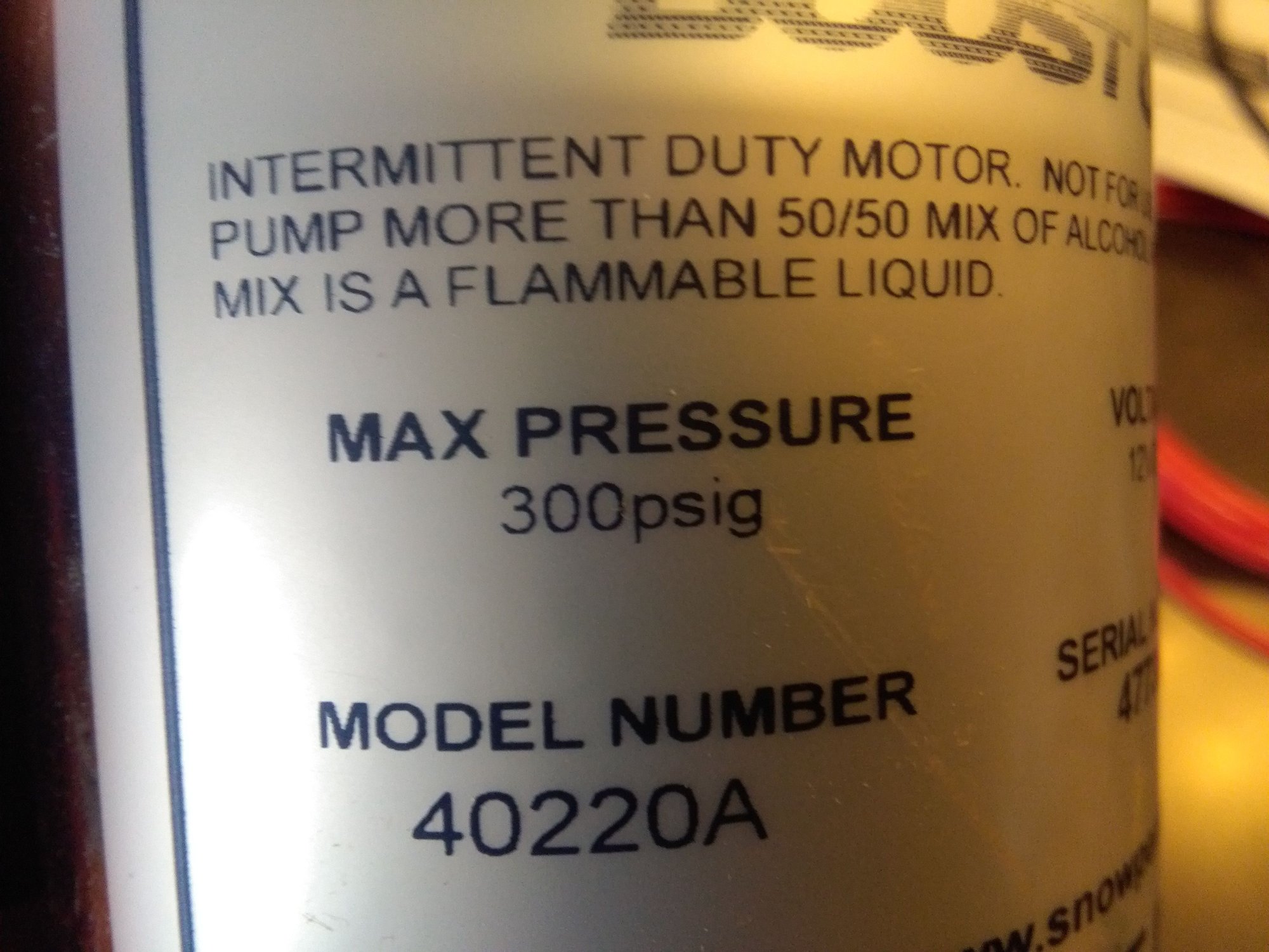
See how huge the 300 psi Pump is. "H.U.G.E."
The ecu that comes with it (the stage two does not electrically interface with the stand alone ecu, which is what I want). It has a built in MAP sensor, requiring just a vacuum hose. Then the injector opens a bit at the chosen boost psi/ and fully opens at the chosen psi. Simpicity... that's what I thrive on.
 04-10-2017, 02:00 PM