When you click on links to various merchants on this site and make a purchase, this can result in this site earning a commission. Affiliate programs and affiliations include, but are not limited to, the eBay Partner Network.
Joe, Does this mean you are getting closer to a MAF system for 944 NA engine, 2.5L or 2.8L stroker engine?
Thank you, Tom
The MAF Controller project is starting to come together, it took quite a while to put all the ducks in a row. Next week I will be using the flow bench I created to map the AFM’s volume to voltage response curve. If everything goes well, I will be able to scale the stock AFM air flow in terms of both volume and density. If I can get to that point, then mapping a MAF sensor and inverting the math to properly emulate the AFM is not difficult. With any luck, I will be into on-road development by the end of the month. However, I fully expect there to be more than one bump on this road. These kinds of projects tend not to be as easy as they seem.
In theory, any stock or performance chip made for the stock AFM will be compatible, but this can only be confirmed after Beta testing. If this holds true, I don't see why it would not be compatible with any 944 NA running stock or stoker engines. They key here is you do not have a custom tune that is based on a MAF kit, that is not going work.
The MAF Controller project is starting to come together, it took quite a while to put all the ducks in a row. Next week I will be using the flow bench I created to map the AFM�s volume to voltage response curve. If everything goes well, I will be able to scale the stock AFM air flow in terms of both volume and density. If I can get to that point, then mapping a MAF sensor and inverting the math to properly emulate the AFM is not difficult. With any luck, I will be into on-road development by the end of the month. However, I fully expect there to be more than one bump on this road. These kinds of projects tend not to be as easy as they seem.
In theory, any stock or performance chip made for the stock AFM will be compatible, but this can only be confirmed after Beta testing. If this holds true, I don't see why it would not be compatible with any 944 NA running stock or stoker engines. They key here is you do not have a custom tune that is based on a MAF kit, that is not going work.
A little bit of topic... Rogue, Ostrich2 and Tunerpro
Hello all,
Some may be running on a dead loop searching good info on Rogue MAF (now LR). I've been looking at all the values from the bin file I extracted from LR chip. It wasn't making sence at all using TunerPtoRT xdf file... Here are the ones I found after searching on Rogue web site that are the good ones.
Note that my LR M-Tune is for 80# injectors 2.5L engine.
In the zipped files you will find :
NA-Tune_Maps.xdf
M-Tune_Maps.xdf
mode1_lr_maf.bin
klr-951-86.bin (could be usefull)
ftech9_ecu.bin (good to compare with LR MTune, I do not have a 944 N/A)
Have fun!
Charles
Last edited by riouxc; 07-19-2021 at 09:35 AM.
Reason: Adding info
Thank you guys so much for the pointers. I tested the AC pressure switch and it made no difference, so it seems like that's not the issue. I've ordered a new temp switch, but the washer is a special order item so it all should arrive next week. I wouldn't be surprised if the issue is just the temp switch since I can hear the relay clicking when the fans alternate, and there was a small coolant drip over the switch that I dealt with a few months ago.
Hi Joe,
I got the new temp switch installed but it looks like that didn't fix the issue. Here's a short video of it with the new temp switch already in -
I got the new temp switch installed but it looks like that didn't fix the issue. Here's a short video of it with the new temp switch already in - https://youtu.be/j-azqnVi1Y0
I'm pretty sure that seals the deal, but is there anything else that could possibly be causing this? The iteration of the relay that I have is 02.
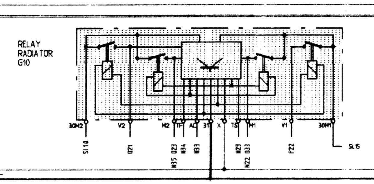
The electrical diagram in the link you provided is for the original "00" relay. Given your testing procedure, the only way this relay would not route 12V to V2 is ether if 12V was not supplied on pin 30M2 or the relay was defective. If you have verified voltage on 30M2 then I would say the latter is true. Newer revision relays replace the smaller "control" relay with electronics, so its failure modes will likely be different. However, I do not see any reason this basic functional test would not be effective on all four revisions.
The electrical diagram in the link you provided is for the original "00" relay. Given your testing procedure, the only way this relay would not route 12V to V2 is ether if 12V was not supplied on pin 30M2 or the relay was defective. If you have verified voltage on 30M2 then I would say the latter is true. Newer revision relays replace the smaller "control" relay with electronics, so its failure modes will likely be different. However, I do not see any reason this basic functional test would not be effective on all four revisions.
- Joe
I definitely supplied 30M2 with 12 volts - I used a benchtop power supply.
Here's the wiring diagram for my specific year (89), so as long as that relay was never replaced, it should be this layout-
I'm not a pro at reading these by any means, but it does look like V2 gets power from 30M2 as well.
Would you recommend that I repair or replace the relay that I have, or wait for the solid state version if it's right around the corner? (No pressure, just trying to gauge the options.)
The problem with your fan relay is ether the specific relay that drives V2 is not functioning or the electronics that drive its coil are defective. I suppose you could open it up and check for something obvious like cracked solder joints, assuming you are handy with a soldering iron. Personally, I would replace it, these relays take a beating over the years, I wouldn't go through the effort of patching it just so it can fail down the road. As for the Solid-State Fan relay, I ran into a supply issue with the fan drivers. I found a potential replacement, but I need to complete some thermal analysis to qualify it. After that, it needs to sent out to the beta testers to verify it functions as expected. Could be a month or so before it is available for sale.
If you are in the USA, I can send you a beta unit to test, PM me with your address if interested.
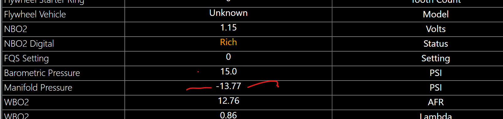
New thing I just discovered. Joe told me that LR is not calculating correctly the MAP sensor... Here is the pressure when engine is off.. Makes no sense, should be at atmospher, 1 BAR or so...
Will investigate on this...
Problem with reference sensors solved with that flange on it... ;-)
BTW, now my engine is flooded again and I think my selenoid is broken... Starter turns free now...
Charles
Hi Charles,
This is not an issue with LR MAP calculation, the OBD+ Module reads the raw analog signal directly and calculates its own pressure value. This occurs when the MAP Sensor signal is not present and the MAP signal is pulled to ground potential. Also, the MAP sensor must be connected directly to the OBD+ module using the provide 4pin "Pig Tail" harness. This is because with the OBD+ Module, PIN 28 on the 35pin system connector is no longer electrically connected to anything. Here is the pinout for the MAP harness:
Hello all,
Problem with reference sensors solved with that flange on it... ;-)
Charles
Is the updated sensor bracket and sleeve only needed for early cars with the opening in the bell housing? Awhile ago I read about this updated bracket and ordered one and the sleeve for my 1989 Turbo... but I probably don't need it, or is it good to have anyway? Thanks, and glad this update fixed your issue.
AFAIK the sensor brackets changed (like everything else from the Early cars to the later ones. The later ones used the updated sensor bracket and the sleeve. They should work fine in your 89 Turbo. Always nice to have spare parts on hand. Did you get the special shouldered screws too? Maybe those got changed out as well..6mmX1.0 is the thread and bolt size on the early cars. Good luck ..
This is not an issue with LR MAP calculation, the OBD+ Module reads the raw analog signal directly and calculates its own pressure value. This occurs when the MAP Sensor signal is not present and the MAP signal is pulled to ground potential. Also, the MAP sensor must be connected directly to the OBD+ module using the provide 4pin "Pig Tail" harness. This is because with the OBD+ Module, PIN 28 on the 35pin system connector is no longer electrically connected to anything. Here is the pinout for the MAP harness:
Red -> +5V
Black -> Ground
Orange -> MAP Signal
- Joe
I will review the wiring on this. If I follow your post, the OBD+ does send the signal to the ADC. And Pin 28 is out of connection, removing this wire from the plug woud not impact anything.
Here is LR diagram that would be useless now:
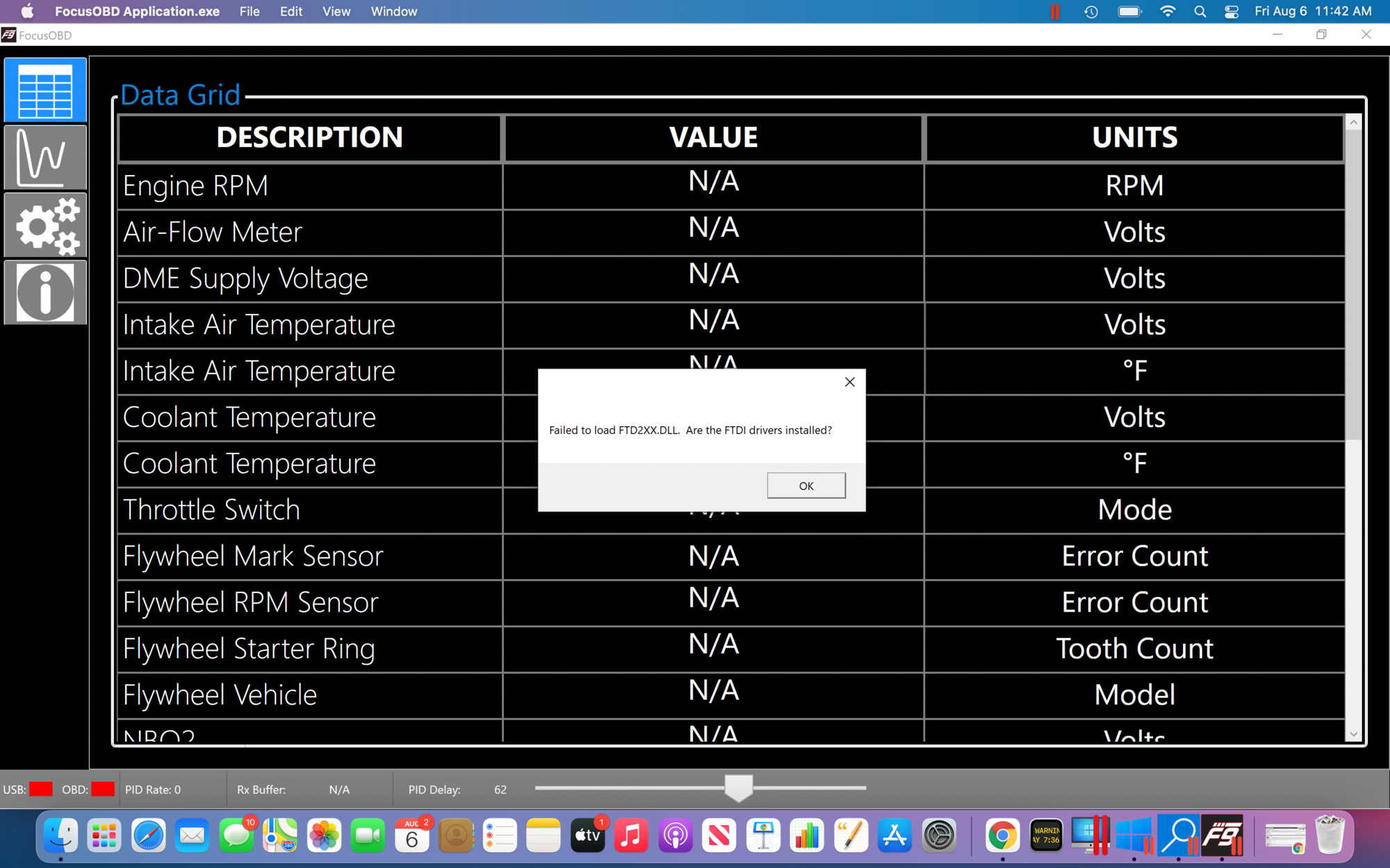
Having trouble connecting DME to OBD software. For starters I'm running windows 10 on a Mac using the Parallels Desktop software. I'm able to download and run the OBD software, however I get the following error and both bottom left corner lights stay red. Be patient because I'm a OS user and know zip about windows 10. Here's what I did:
Downloaded the OBD software using Windows Microsoft Edge
Installed the OBD software
Launched the OBD software (see error message)
Connected the USB cable - computer asked if I wanted USB to work with OS or Windows 10; I selected Windows 10
Turned the key on
Nothing happened- both indicator lights remained red and values N/A
Any help you can provide will be appreciated.
thanks


 07-17-2021, 01:55 PM