When you click on links to various merchants on this site and make a purchase, this can result in this site earning a commission. Affiliate programs and affiliations include, but are not limited to, the eBay Partner Network.
My fan relay decided that running the fans was the meaning of life, and doing it 24/7 would be even better (well, at least until the battery died).
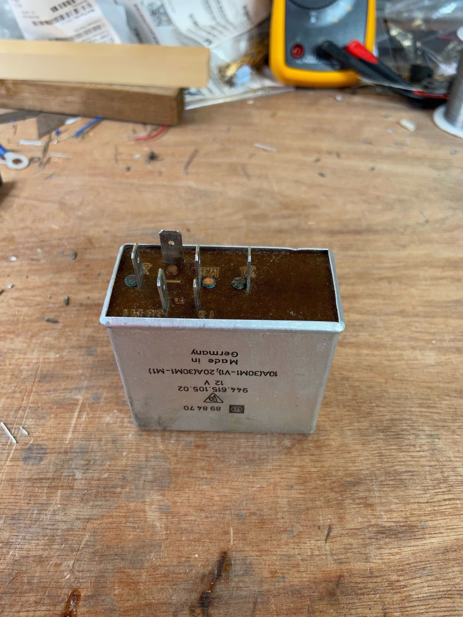
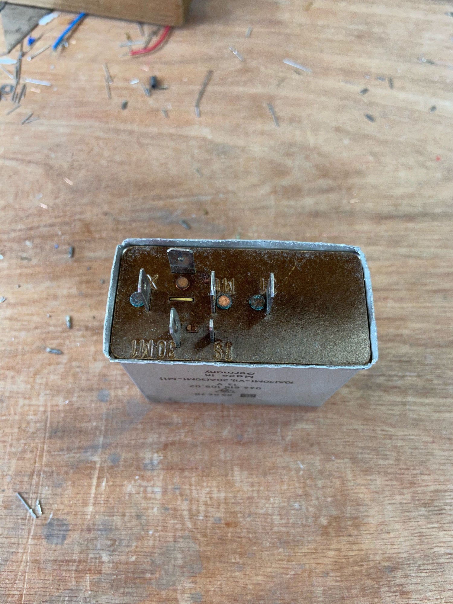
Here's where the trouble starts. Irish cars without AC have only a single fan, and while they're still 2-speed, there's only a single 92� temp switch. So you can see the right half of the "normal" fan relay appears to be missing.
Prying the case open:
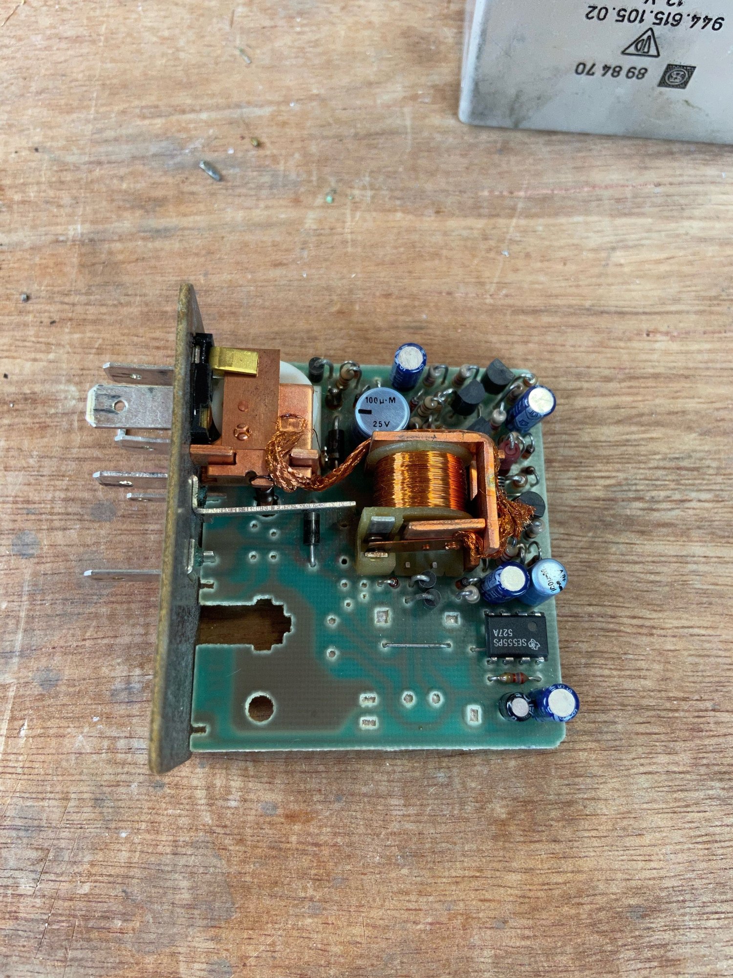
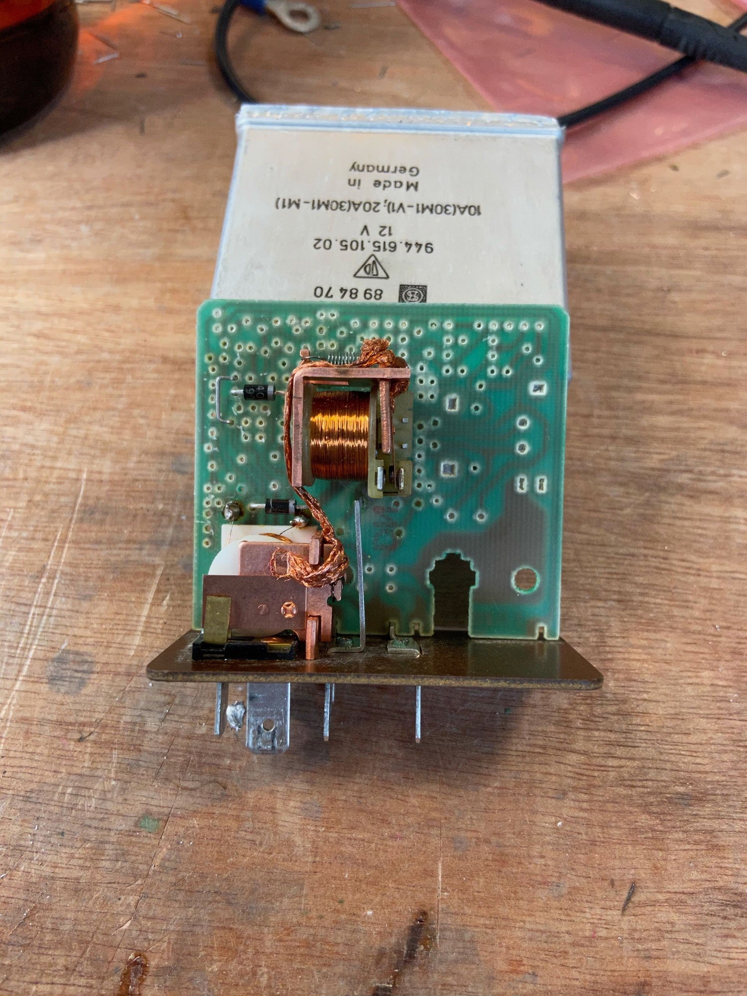
Guts:
Slow-speed relay at the base of the module; full-speed in the middle.
The 8-legged critter is a timer.
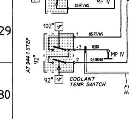
The schematics show the temp switch thusly:
Helpful, huh? The "1 step" comment leads me to believe it's still an on/off rather than a sliding resistance. So what controls slow vs full-speed?
My guess is it's the timer. Perhaps after running for a certain amount of time it decides to kick up the speed to full. (Or maybe that's to control the amount of time they'll run after turning the ignition off? But then what does the speed control?)
Anyway, I inspected the board and there were no cold or cracked solder joints. I reflowed the ones on the relay anyway, but it didn't help.
Based on my experience with my former '79 Bentley T2, the diodes are the first things to go. So I replaced those. Still no better.
Fortunately I live in Ireland. If I leave the house on either day of summer, I'll probably take one of my cars with AC. So I rebuilt the fan relay with a single, low-speed circuit controlled directly from the temp sensor, with a protection diode and a fly-back diode across the relay coil. I left the second relay on the board as a spare, but everything else got binned.
(BTW my 1988 model 944S does not have the three way connector shown in the Clarks manual, just two spade connectors, and only one fan. Maybe UK models were different?)
No, sadly I've put it back in the case (which isn't going to take much more bending/unbending).
I do think I've discovered a couple of things though. My single-fan relay in the double-wide case is a 105.02. The double fan version is 104.02 -- and interestingly also has the timer. So I suspect it's more to do with run-after-shutdown than speed control.
I also found a later iteration of the single-fan relay (in a single-wide case, 105.03) which forgoes all the electronics and controls the speed based on whether or not the ignition is on (if so full speed; if not slow speed). So I suspect that's what 105.02 does as well.
I am curious as to what it does now, though. That's a pretty egregious parts count if it's just a fan-off delay circuit. (I thought it might be a hysteresis circuit, but presumably the temp switch is some sort of bi-metal device which has its own hysteresis. And if not, how can they get away without it in the 105.03?)
Eh, no worries! Might be able to make enough out from your pictures - otherwise I can split one of mine. I have notes from the blinker relay somewhere too - Think it would be kinda nice to have some public documentation around these. I'll add it to the list
That was my initial assumption as well - the cluster of BJTs are probably just drivers to let the 555 switch those relays, maybe with some latching behavior as well - Kinda curious, since you can definitely make a 555 do a timed one-shot.
That's a pretty egregious parts count if it's just a fan-off delay circuit.
It really is...Is that 100u/25V part an inductor? Can't tell from the angle. But if so, curiouser and curiouser....
Originally Posted by jeyjey
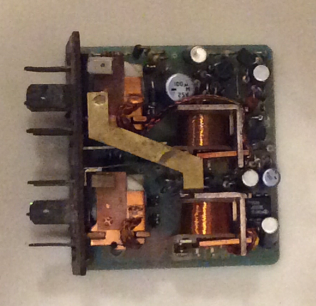
Here's a crappy picture I found of the guts of the (twin-fan) 104.02:
Speaking of egregious BOM count - it looks like they just stuffed the entire board minus the relay/contacts for the 2nd fan. Clearly they weren't trying to source components in 2021
Oh, and I'm reasonably sure the fan speed is controlled similarly to the HVAC fans - just driven through a high wattage resistor for low speed. Should be in the schematics somewhere.
The fan speed is controlled by a large 0.9 ohm resistor located on the firewall. On the relay M1 bypasses the resistor so the fan runs on high speed, whereas V1 feeds the fan via the resistor and so runs the fan at low. The relays in the coolant fan relay are told what to do by the thermoswitch (amongst other things). On cars with two fans the coolant fan relays also have M2 and V2 terminals and a second resistor for slow/fast on the second fan.
The relays in the coolant fan relay are told what to do by the thermoswitch (amongst other things).
It's the "amongst other things" that I'm wondering about as on the single-fan cars the thermo-switch is a single 92� switch (not a 92�/102� pair like on the twin-fan cars).
It can work several ways to be two speed with a single temperature switch.
1. Temp switch enables, low speed runs for a set time. If signal exists for X time, low speed coil de-energizes, high speed coil energizes. But, I cannot tell from the photo if the lower part of the relay is also a coil. Looks like it could be, but need to see a side photo to be sure.
2. If relay is single coil and has only a single temp switch, it runs through the resistor via the temp switch. With ignition on, car running and temp switch engaged, the circuit is wired direct to fans via the relay for full speed. (Circuit will follow path of least resistance and naturally bypass the fan resistor) If the ignition is switched off, or the ignition is on, but the AC is on and calling for the compressor clutch to be enabled, the circuit is wired to run via the resistor causing a low speed condition until either the AC compressor is switched off, or the temp switch opens.
I know that may sound confusing, but it's the way many cooling systems operate via a single temperature switch. Without diving into the schematics for your specific model, this is just my guess. It's similar to how the early year model 944's fans operate at dual speeds with a single switch. They just don't have any solid state controls built into the relays like yours does with the timer. If your temp switch is testing fine, you have a failed relay.
It's the "amongst other things" that I'm wondering about as on the single-fan cars the thermo-switch is a single 92� switch (not a 92�/102� pair like on the twin-fan cars).
The ignition and AC are the other things. AC on/high-pressure/high-temp all have an effect on that circuit. This write up by StoogeMoo may help, just ignore the second fan circuit.
Coolant Fan Relay (G10)
X ignition -- on=12V off=0V
TF temp fast -- on=0V off=float
TS temp slow -- on=0V off=float
AC air conditioning -- on=12V off=0V
31 ground
30M1 fused 12V 25A
30M2 fused 12V 25A
M1 cooling fan 1 high speed
M2 cooling fan 2 high speed
V1 cooling fan 1 low speed (via external resistor)
V2 cooling fan 2 low speed (via external resistor)
�X� is at 12v with the ignition on which closes relays R1 and R2 if �TF� is grounded.
Here's how to test it without actually opening it up. I used a battery charger for the 12v supply and numerous alligator clips and jumpers. Apply 12v to terminals 30M1 and 30M2. Apply ground to 31.
1) Ground TS. Terminals V1 and V2 should go to 12V indicating slow speed fans. Remove ground on TS. V1 and V2 should go to 0V.
2) Apply 12V to AC. Terminals V1 and V2 should go to 12V indicating slow speed fans. Remove AC. V1 and V2 should go to 0V.
3) Ground TF. Terminals M1 and M2 should be at 0V. Apply 12V to X. Now M1 and M2 should go to 12V indicating high speed fans. Notice that M1 and M2 don't go to 12V until the ignition (X) is turned on.
Yeah, I did see StoogeMoe's write-up, but I was unable to assign that to a part. Clearly it's a twin-fan, twin-switch system, but it's not the "early" system, and it's not the one with the timer either. Was there something in between?
In StoogeMoe's case the logic is: low-speed if 92� -or- AC; high-speed if 102� -and- ignition on.
Since all AC cars have a twin-fan, twin-switch system, the single fan equivalent of StoogeMoe's logic would be: low-speed if 92�; high-speed if 92� -and- ignition on (which is also exactly what 105.03 does).

 05-13-2021, 05:03 PM