When you click on links to various merchants on this site and make a purchase, this can result in this site earning a commission. Affiliate programs and affiliations include, but are not limited to, the eBay Partner Network.
Great big KUDOS to you on getting past the state inspection! Hope that it continues to run well for you..Do you plan to change over from batch fire to sequential any time soon? Seems that you could get a better power balance that way...jus wondering..
Thanks guys! couldn't have made it this far without good ideas from the community.
Originally Posted by Tiger03447
Do you plan to change over from batch fire to sequential any time soon? Seems that you could get a better power balance that way...jus wondering..
The thing about Microsquirt is that it only has 2 injector channels, so sequential fuel isn't possible. I'm currently running it in semi-sequential, which means that the "squirt" is divided into two squirt events. More info here, about halfway down. I would have to get a different Megasquirt controller if I wanted to add 2 more injector channels, but quite honestly the car idles like silk and I have zero problems with semi-sequential for street use.
Now while Microsquirt only has 2 injector channels, it has up to 4 ignition channels, so sequential spark is a possibility. For that, you need a cam position signal. With just a crank position signal, the cam might be at TDC or BDC whenever the crank is at TDC because the cam spins half as fast as the crank. With wasted spark (which is what I'm using) you only use 2 ignition channels and do not need a cam position sensor - the spark fires at every crank TDC event (hence "wasted spark").
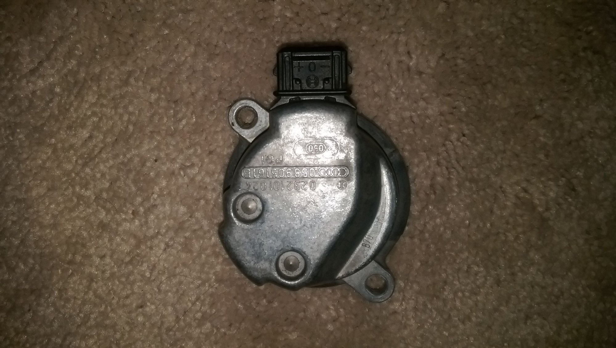
However...this is probably really boring and dry, but had a thought earlier this week. At the local junkyard I pulled some Audi/VW camshaft position sensors and they seem viable for a 944 application. This is only relevant for those wanting sequential fuel or spark - I probably won't go down this road but I figured others might.
It's pretty simple - that disk with a notch in it (2nd pic) is bolted to the camshaft, where the distributor rotor was. Then the main housing bolts over it - the holes are similar to the two distributor retainer hooks but a basic bracket will have to be made. It shouldn't be hard given the bolt holes available from the cam gear cover and everything. At that point, the sensor mounted in the housing detects the notch in the spinning disk and sends this as a signal. The connector even has "| + | 0 | - |" on it to signify power, signal, and ground so it seems like the easiest possible way to get a cam pickup for sequential fuel or spark.
The 16V engines have a cam sensor in the back of the cam pulley housing. I don't know if they swap over or not, though.
That's probably the best solution, I've just never seen a complete 944S in person and have no idea. But yeah, that would be really clean assuming the cam gear had the provision for the pickup to read it.
Edit: I forgot! The wiring is basically done. Made a quick video of the final steps needed to remove the factory harness without losing functionality, and also the tach setup.
So a couple people asked about tuning maps...finally got things in order on that front. Not perfect - but very drivable and in my car, pulls a lot harder than the DME ever had it. This is not a dyno tune but is very streetable. I generally tweak it every time I drive, so this is more of a 'starting point' than a final word. Another important consideration is that my motor is probably different from yours if you download and run this tune...I have a slightly more aggressive cam than stock, and a 5 angle valve grind which will make my VEs a little higher at high RPMs. However, this will still work ok for a stock 8v 944 NA, just be prepared to tweak and refine. DO NOT load this map without intending to follow through and tweak it for your own application.
The MSQ file also includes an ignition map - it is very conservative and when my car is dyno tuned, I'll share it. But that should get you started.
Make sure you go through all the engine setup setting and make sure it is configured right! There are a lot of areas where my build is different. For example - tooth #1 angle (missing tooth offset relative to TDC), the coil dwell and configuration, and the req_fuel variable. req_fuel is very important, unless you used the same injectors as me yours will be different. You need to have all this ironed out before you load anyone elses tune.
Another thing is the enrichment curve setup. Mine is tailored to a car with an early aux air valve and a lower temp thermostat than stock. Yep, even stuff like your thermostat comes into play because that affects how the car warms up. So long story short, you need to redo all the settings that transition the engine from cold to warm.
Alright, all warnings aside, this is totally worth it and hopefully this makes it more accessible for other 944 enthusiasts to migrate to a standalone setup if they desire to.
A little blurb about the coolant temp sender, for all those who asked me if I could document the install.
The stock part will work, the tricky bit is calibrating it. Assuming the sender is in spec, and you are using TunerStudio, go to "Calibrate Thermistors" and select "BMW E30 325i" under "select a common sensor" drop-down menu. This calibration is for a Bosch 0 280 130 026 coolant temp sensor.
According to some 'parts cross reference' lists, this is the same part as a 944 stock coolant temp sensor. If you have any doubts, just buy a brand new part. If you search "0 280 130 026" you should find plenty of online retailers. The 944 head is tapped for the thread on it, so it is plug and play. The aforementioned BMW E30 built-in calibration is designed for this part - you should still verify that you are getting reasonable readings in TunerStudio. If not, make sure the sensor is cleanly grounded via the signal ground.
I've been dailying the car for a few weeks now with zero problems whatsoever... a lot of credit where it's due for the Microsquirt hardware and TunerStudio software.
Today, I got the cooling fans running via the Microsquirt. For whatever reason I've had a run of bad luck with Wahler fan switches, I've gone through 4 in under a year and a half. Every time, they seem to fail in such a way that the fans stay on and I wake up to a flat battery. So for me, it seemed worthwhile to control the fans with MS.
Basically, a relay is installed in place of the fan switch. The relay is switched on by MS at a target temperature. Unlike the fan switch (where you have to physically replace it for a different activation temperature), the target activation temp is a software setting in TunerStudio and can adjusted on the laptop or smartphone on the fly.
MS provides a ground to the relay, so all the user really needs to do is hook up the other activation pin to a 12v source. Then, hook up the two load pins to the two spade terminals that would usually plug into the fan switch. Voila! No more failing fan switches, and complete control over the activation temperature.
Cool that you can do that...but I feel you may have some other issue causing fan-switch death.
It's just highly improbable that 4 would fail in that short time.
Mine's never given me a single problem and it's at least 6 years old, I think.
I know that my coolant temps are fine, but there is a question I have. As you know there are 2 wires that go into the early fan switch...one is +12v, and the other one receives that +12v once the switch activates. My question concerns the "cleanliness" of this voltage, but really the current in those wires. Here's how I tried wiring the relay at first:
I wired the two fan switch wires to pins 30 and 87 to duplicate the functionality of the switch
Note that the +12v that goes into activating the relay is tapped from the +12v that eventually is let back into the harness. As soon as the target temperature was reached, the relay was buzzing out of control, as though it was activating many times a second. The fans seemed to work still but the relay was making a racket. I killed it and the relay was very hot to the touch.
Is there an element in the fan circuit that could fail in such a way that the current going through the fan switch was very choppy? The fans run fine when the +12v for activation is taken from a different source, as you can see in the video. Wondering if that irregular current could be the explanation for the failures.
Fans will generate a lot of noise on their voltage supply, especially at startup. If your signal line is running off that supply and it is noisy enough, then you will essentially be getting rapidly alternating on/off signals on the signal line. This will cause more noise on the the voltage supply due to the toggling relay and you will end up in a feedback loop that never stabilizes. Running the signal from a cleaner voltage source would eliminate that feedback loop.
Getting your signal from a far away source would work, or putting a filter on the signal line would work also. Just a capacitor between signal and ground might be enough, and you can add a resistor to the signal line for extra filtering.
That makes sense, thanks. Current plan is to take the +12v from the fuel pump relay, so during warm cranking the starter will get a turn or two in before the fans start to compete for current from the battery. (MS grounds the fuel pump relay once the engine starts spinning)
Fans have been running perfectly the last week, just needed the cleaner +12v source.
Although the main work is done, there are still some areas I'm working on, and am starting to tackle on the weekends. An important area that I admitedly half-assed was the spark plug wires. The LS-series wires are too short, and traditional distributor wires won't make contact with the terminal on the coils I have. My interim solution was to use wires intended for a late 90s GMC truck, which have been fine but are way too long and probably original wires.
So I decided to get some custom MSD stuff, which was a lot less expensive than I thought, about $63 shipped (all from Amazon). Should be here in the next week. It's a DIY job, the end-user does the cutting and crimping. shouldn't be too hard, there are a lot of good videos on youtube of people explaining the process.
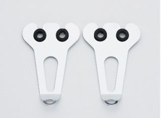
I also snagged some brackets on fleabay that will suspend them over the cam tower, there were $4 shipped.
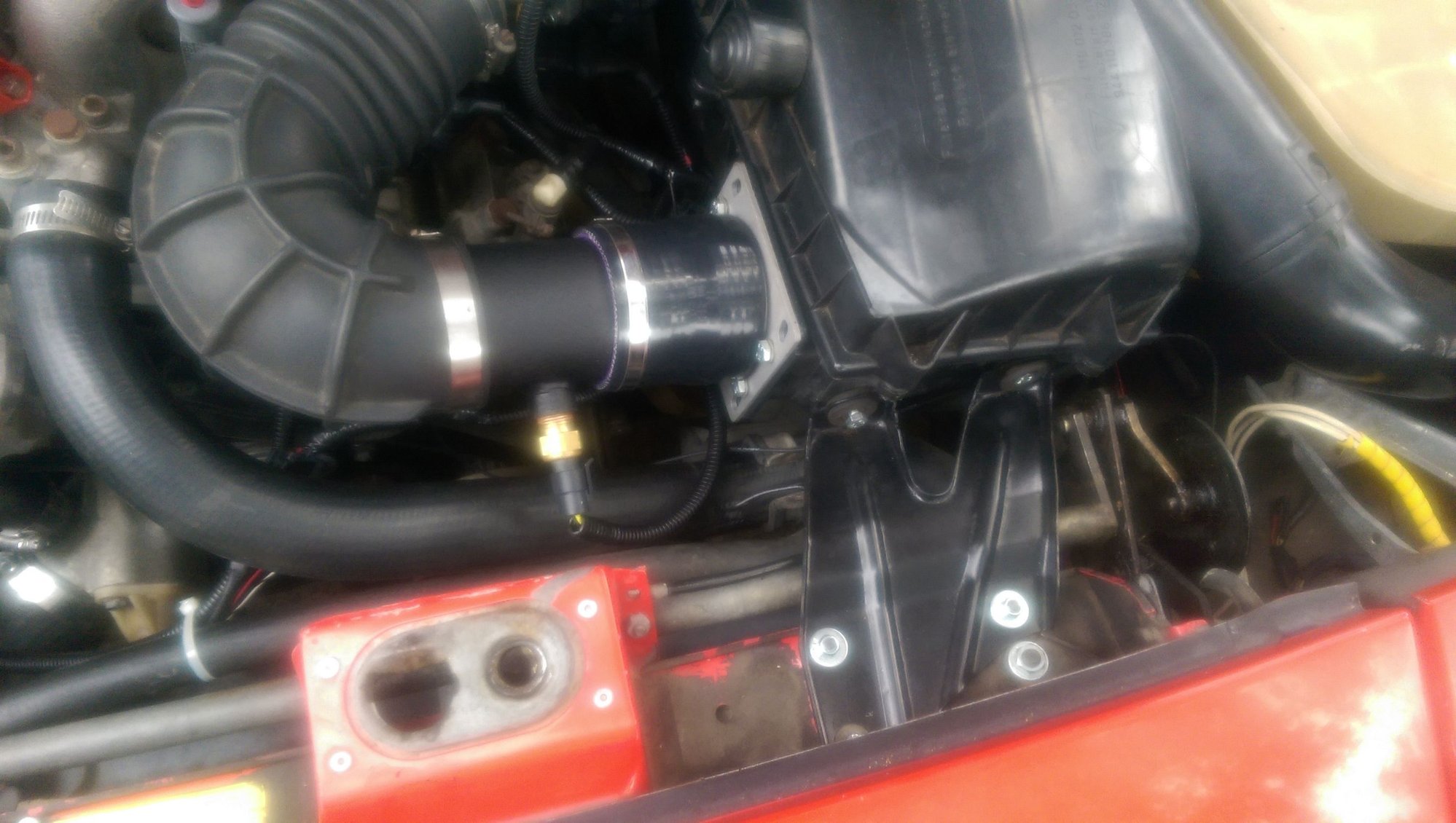
Next area of attention will the IAT sensor, which again, I admittedly half-assed just to get the car up and running. I have a K&N cone filter and the IAT is just sitting next to it right now...it's usable but I'm not happy, I want to use the stock airbox.
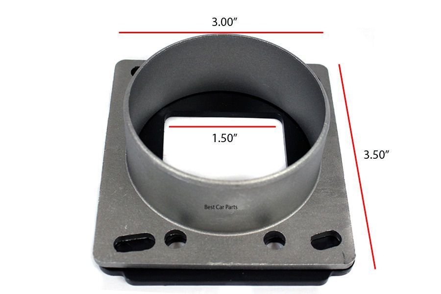
...and use a BMW E30 MAF adaptor so it can bolt to the airbox. Total: ~$50 shipped. The IAT tube from Bell can be ordered in different lengths and diameters, so there should be no problem with one end being hose clamped in the stock J-boot just like the AFM was. I'll order this stuff tonight once I make some final measurements.
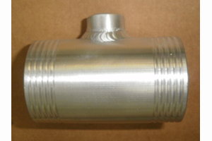
Finally got the final part in today... the IAT sensor tube from Bell Engineering. It took about a month to get it but it's worth it, especially since they custom made it with the dimensions I provided (length = 4" and diam = 2.75"). It's powdercoated to combat heat soak.
I think my phone's camera is on the way out...image quality is getting worse and worse. Anyway, the car hauls *** these days! Josh at Rogue Tuning threw together an ignition map based on my VE table and the car is even smoother than before. Feels better than a modern car in a lot of ways... it behaves so well given how "primitive" it is. If anyone is interested in tables or general conversion strategy, let me know cause I'm happy to share what I've learned.


 08-06-2015, 09:32 AM