When you click on links to various merchants on this site and make a purchase, this can result in this site earning a commission. Affiliate programs and affiliations include, but are not limited to, the eBay Partner Network.
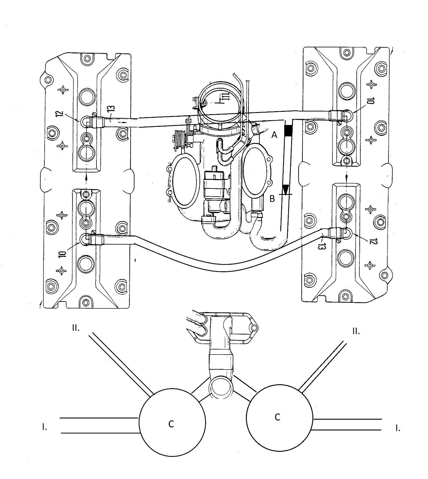
The following sketch describes the proposed implementation of the external crankcase breather system:
The above design operates under the assumption that both front valve cover elbows don’t have restrictors or have the restrictors drilled out. The rear valve cover breathers should also not have restrictors, although this is less critical. The rear valve cover elbows should have separator tubes or some other devices that minimize oil being transported out with air. It is mildly beneficial but not necessary for the front valve cover elbows to have separator tubes.
The logic behind connecting the valve covers (like in the late GTS design by the factory) is twofold.
First, connecting the two valve covers together sets up a low-frequency circular gas flow motion from the passenger side valve cover to the driver side valve cover, then down the driver side oil drains, oil pan, up the passenger side oil drains, and finally back to the passenger side valve cover. This circulation will be more or less a constant flow without significant pulses, because the pulses average in the valve covers per bank. The circular gas flow motion helps to evacuate water vapors and hydrocarbons with low boiling points.
Second, the interconnect hoses between valve covers may help under lateral acceleration forces. Suppose that the engine is subjected to a lateral acceleration force, effectively tilting the engine sideways. If the valve covers are isolated, the following situation may develop. The oil drains of the bank that is effectively horizontal may fill with oil. This oil prevents gas flow up and down the drain channels. If the crankcase pressurizes while the valve cover does not, the pressure differential may push oil into the valve covers.
Connecting the valve covers to each other with a large enough hose will alleviate the above described problem in the following way. Because the opposing bank is now effectively vertical, the oil will drain easily to the sump and gas can flow freely thru the drains. The higher gas pressure of the crankcase will first be relieved into the opposing valve cover and from there to the other valve cover thru the interconnect hoses. This will equate the pressure between the crankcase and valve cover in the bank effectively in horizontal position, reducing the likelihood that oil will be pumped into the heads.
The rear interconnect between the valve covers has a t-fitting that connects to the intake manifold plenum via a hose. This hose that has two devices. The first device, labeled A, is a metering orifice. It is meant to replace the existing 2mm diameter metering orifice in the oil filler neck, and should be sized consistently. The purpose of this 2mm orifice is to both limit the vacuum that can be drawn into the crankcase and to create a leak of the size that matches the idle adjustment controller sizing. The second device, labeled B, is a check valve. This check valve makes sure that manifold pressure under boost will not cause air to flow from the intake plenum into the crankcase. This check valve is already incorporated in most forced induction designs.
In terms of fabrication, the existing complex hose could be modified for example in the following way. First, the hose is cut near the intake plenum and an in-line check valve is inserted to rejoin the hose. Second, the hose from the oil filler neck is disconnected and joined with a 2mm restrictor coupler to another, new hose section. This new hose section is then joined with a T-fitting to the interconnect hose between rear valve cover ports. Third, the part of the complex hose that connects to the electric valve that vents the activated charcoal canister will be left unmodified. Alternatively, the 2mm metering orifice may be integrated to the T-fitting that connects to the valve-cover interconnect hose.
In addition to the shroud separator tubes inside the valve covers, the proposed design will have two types of main air-oil separators. First, there is an air-oil separator installed inside the block under the oil filler neck (not shown in the above figure).
Second, there are air-oil separators with as large of cross-sectional area as possible to fit in the engine bay on both sides. These second-type air-oil separators are labeled C in the sketch. The second-type separator has one inlet which is connected to the oil filler neck with a minimum � inch hose. Alternatively, the second-type separator may be integrated directly to the oil filler neck. Both alternative solutions require modifying the oil filler neck for a large breather port on each side.
The second separator air outlet connects to upstream of the compressor inlet, for example, to the air box (labeled I) via a large, minimum � inch hose. With draw-thru MAF conversions, the connection would be between the MAF and the compressor inlet. In either case, the connection point must have filtered air.
The second-type separator also has oil drain outlet, which will be connected to one of the turbocharger oil sumps (labeled II) that is actively scavenged by an electric pump. Because of active scavenging, there is no need for a check valve in this line. The hose from the separator to the oil pump has to be large enough diameter to allow gas flow in both directions. The turbocharger oil drain produces foamy air-oil mixture and the vented sump will both result in a stable back pressure for the turbocharger oiling system as well as allows for air-oil separation. This venting mechanism also eliminates any need for interconnect between the turbocharger oil sumps. Note that the second-type separator C has to be bidirectional in this schematic.
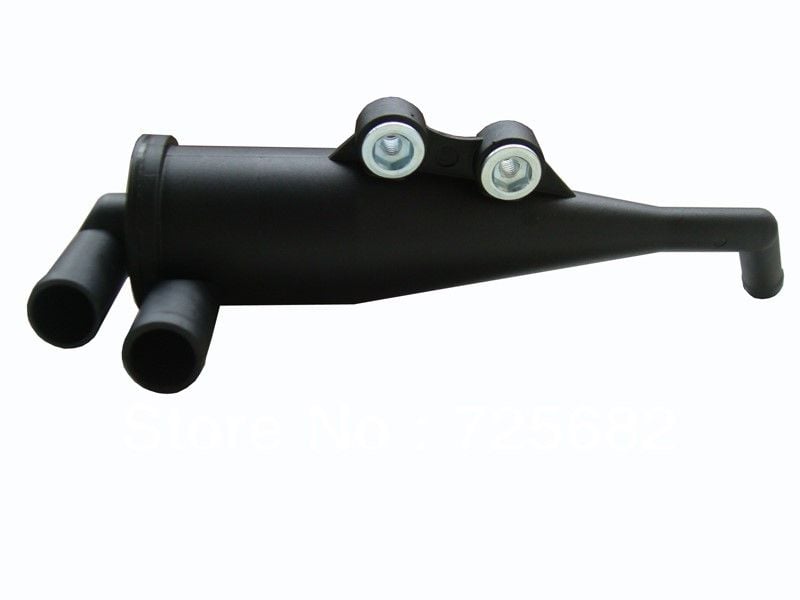
Two air-oil separators from BMW (part number 11151705237), will likely work well:
The BMW separator can be connected to �” gas in and outlets and �” oil outlet hoses.
The passenger side port of the MAF boot will be plugged, as well as the unused port(s) in the oil filler neck. If the catalytic converter secondary air pump circuit is retained, one of the unused ports in the oil filler neck can be repurposed to feed the secondary air valve.
At idle, there is significant vacuum in the intake manifold plenum, of the order of 18 in Hg. The crankcase and valve cover pressure is close to atmospheric. The pressure differential opens the check valve B. The intake manifold sucks crankcase gasses, but the quantity is limited by the 2mm restrictor A which prevents the engine from surging.
The crankcase gas sucked into the intake manifold is ultimately replaced from upstream the compressor inlet which at idle has close to atmospheric pressure. The replacement gas will have to travel thru the separator C, oil filler neck, the separator inside the engine block, oil drain channels, and valve covers. It is important to note that this design assumes that both the separator inside the engine block and the separator C can flow a small quantity of air in reverse direction. This process will remove harmful vapors from the crankcase and replace them with fresh, unsaturated air.
At low rpms and throttle closed, oil drain from the heads is not an issue regardless of the direction at which the crankcase is vented. Similarly, appropriately positioned hoses are unlikely to suck significant quantities of oil into the intake at idle.
Operation with manifold vacuum and high rpms
Under conditions in which the engine rpm is high and the throttle is closed, the manifold can develop significant vacuum, in some cases of the order of 24 in Hg. This temporary condition is usually a result of the throttle being closed at high rpms.
Usually, when the throttle is closed at high rpms, the car is initially traveling at relatively high speed and will begin to decelerate. This is because of the brakes being applied, engine braking, and/or aerodynamic and rolling frictions. The deceleration process will cause loose oil in the valve covers to slosh forward towards the front of the car. With the rear valve cover interconnect set to a suitable attitude, any oil that is inside the interconnect hose will drain back to the valve covers and also slosh to the front of the valve cover.
The pressure differential between valve covers and intake manifold will cause the check valve B to open and crankcase gasses to flow into the intake manifold in quantities controlled by the restrictor A. Because of the deceleration forces, it is unlikely that significant quantities of oil will be ejected into the intake manifold. Even if some oil is ejected into the intake manifold, it is now downstream of the MAF sensor and cannot foul the sensor wire.
The replacement gas to the crankcase will come mainly from two sources. First, from the intake tract upstream of the compressor inlet. Second, as blow by gasses that are passed thru the piston rings, although it is possible that the blow by flow is negative because of the combustion chamber vacuum.
Operation with positive manifold pressure
At high loads and high rpms, the intake manifold sees positive pressure. The positive pressure closes the check valve B. The rear interconnect hose will function simply as a connection between the valve covers.
Despite our best efforts, an outlet pipe normal to the compressor inlet flow will likely have relatively low static pressure. This low static pressure will suck crankcase gasses thru the external separator, oil filler neck, separator in the block, and crankcase. The crankcase will either experience a mild vacuum or mild pressure, depending on the quantity of blow by.
Because no crankcase gasses are vented out thru the valve cover, the crankcase ventilation should not hinder oil drain from the heads.
At high loads and high rpms, the car is more often than not accelerating forward. The separator C should be routed in a way that any loose oil in the oil filler neck will flow back into the block due to acceleration forces. This will further reduce the oil separation needs.
Wow! Thank you for the best theoretical discussion I've seen of the 928's oiling and crankcase breathing issues. It seems that the system designed by Porsche maxed out with the S4. With the GT, the system was overtaxed, but only when the car was driven especially hard. With the GTS, the system (for a variety of reasons) simply cannot do what needs to be done. This explains why Greg Brown's strokers need his oil management improvements.
When describing your proposed solution (which time and testing will either prove or disprove as being an actual solution), I thought you were going to enlarge the 2mm restrictor to allow more crankcase gases to be ingested into the intake. You did a good job of explaining why this could not be done.
Very interesting explanation. It's appreciated.
Last edited by DKWalser; 03-23-2016 at 11:23 AM.
Reason: To correct typos
When describing your proposed solution (which time and testing will either prove or disprove as being an actual solution), I thought you were going to enlarge the 2mm restrictor to allow more crankcase gases to be ingested into the intake. You did a good job of explaining why this could not be done.
One person has been testing an analogous system in a normally aspirated motor, and there are a couple others that will do that soon. The person testing the analogous setup in his normally aspirated car may or may not choose to publicly share the results, be they positive or negative, or something in between.
The real test will be the turbo car, given triple the air flow and thus triple the expected blowby.
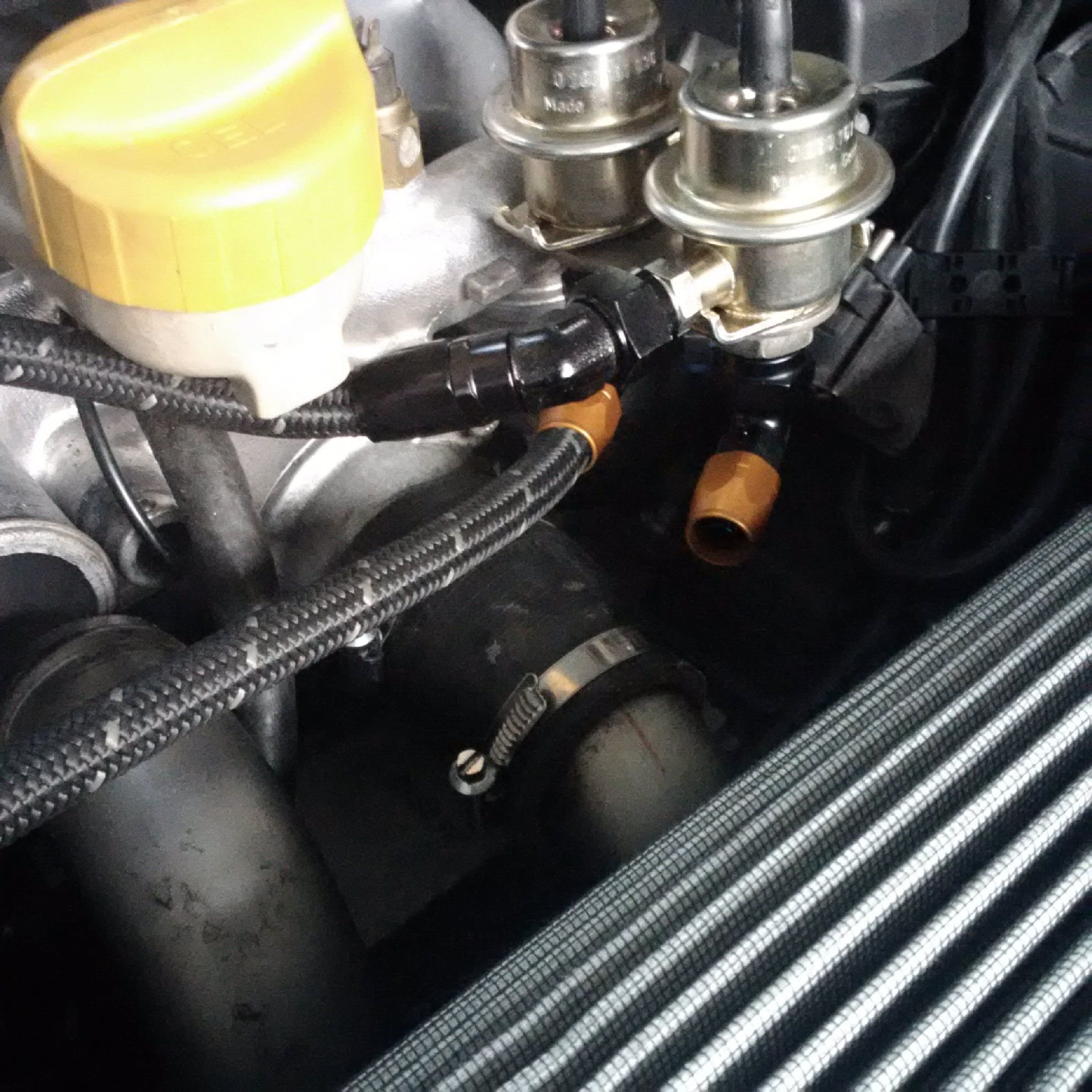
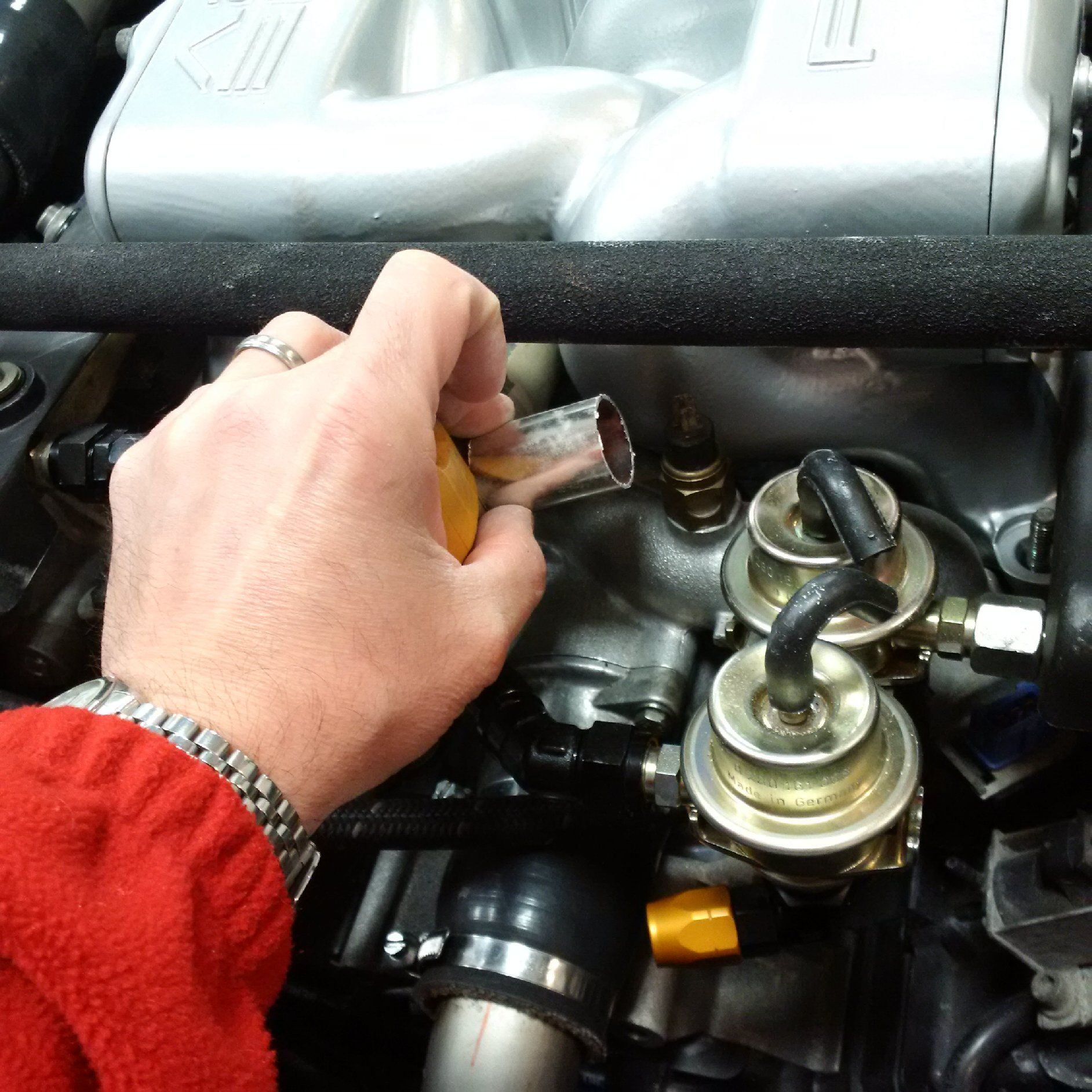
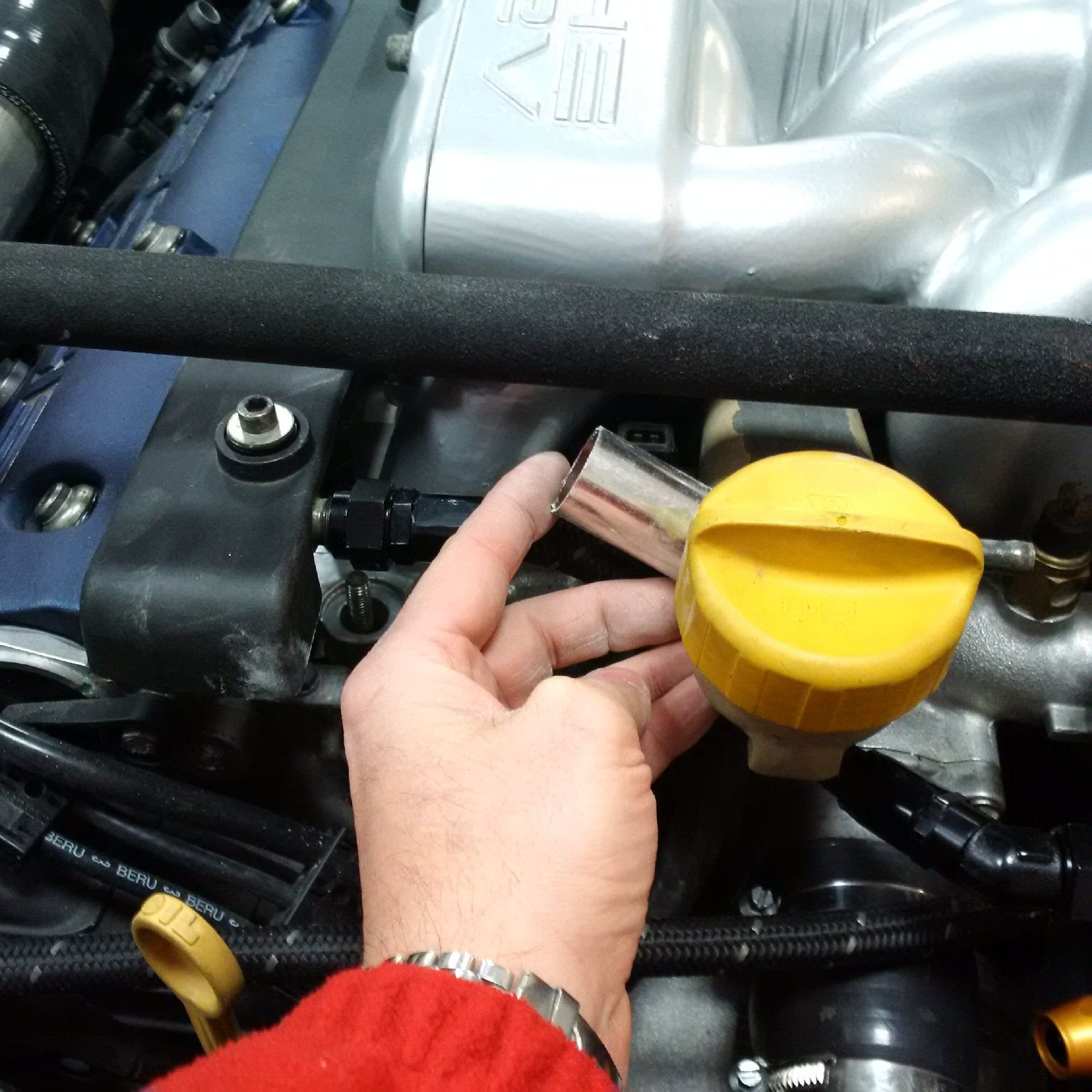
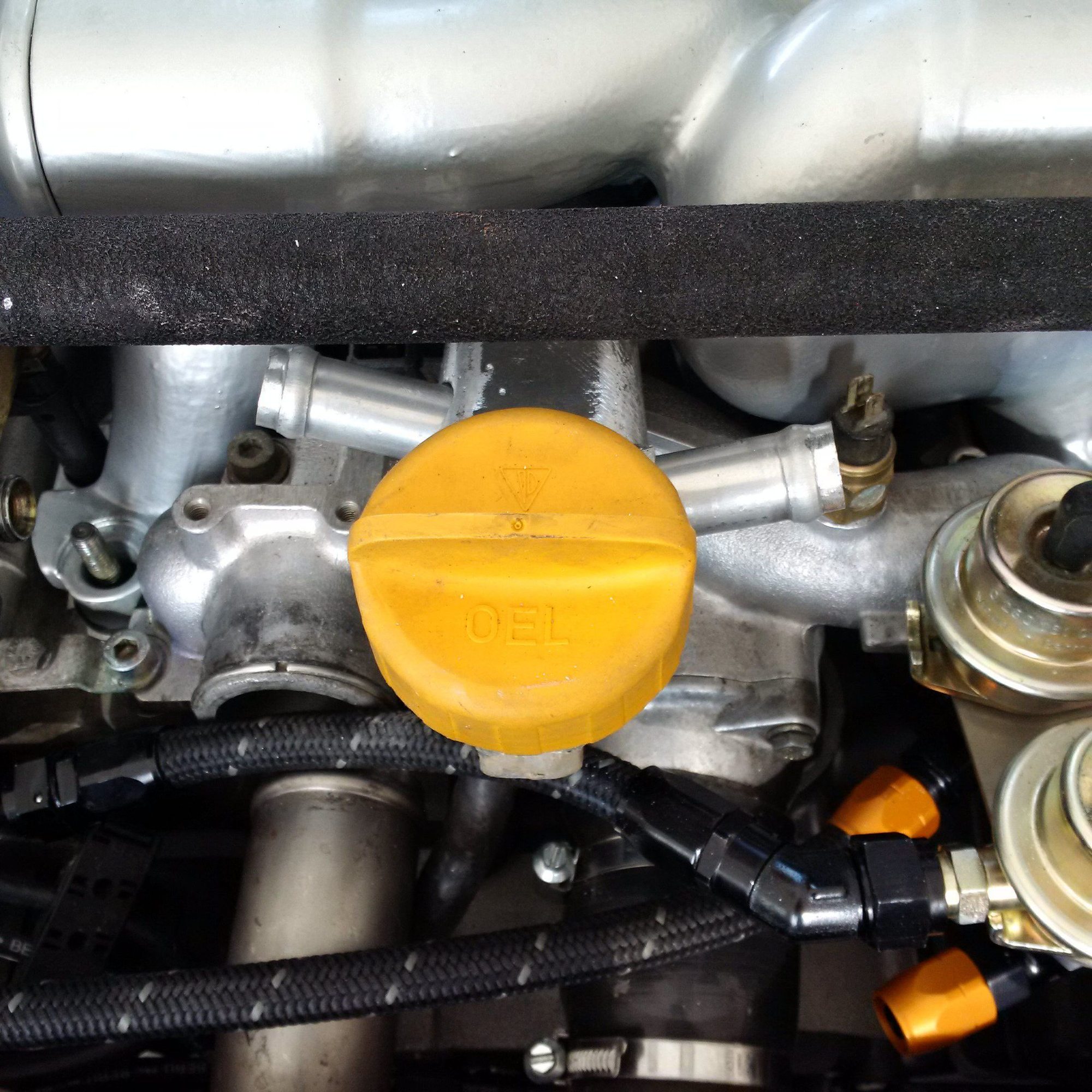
The previous iteration of fuel lines need to be redone and rerouted to make room for a neat installation of the new crankcase breather system. We need smaller hose end fittings that furthermore have to be compatible with the 951 fuel pressure regulators. The fittings have golden covers, but we can replace those with black ones to keep the overall color scheme consistent.
The fuel lines will be stainless steel braided lines, which will help a little bit with the heat dissipation but will require fairly careful bracketing. Loose, vibrating stainless steel braided lines are not something you want rubbing against any other components.
(Hose in the picture is not the final version, it's there just for test fitting,)
The crankcase breather lines will be black rubber(ish) hose the ports fabricated to the magnesium oil filler neck. While testing, we're running the crankcase breather lines outside of the intake manifold. Once we're sure the system works, most of the lines will go under the intake manifold and under other pipe work etc.
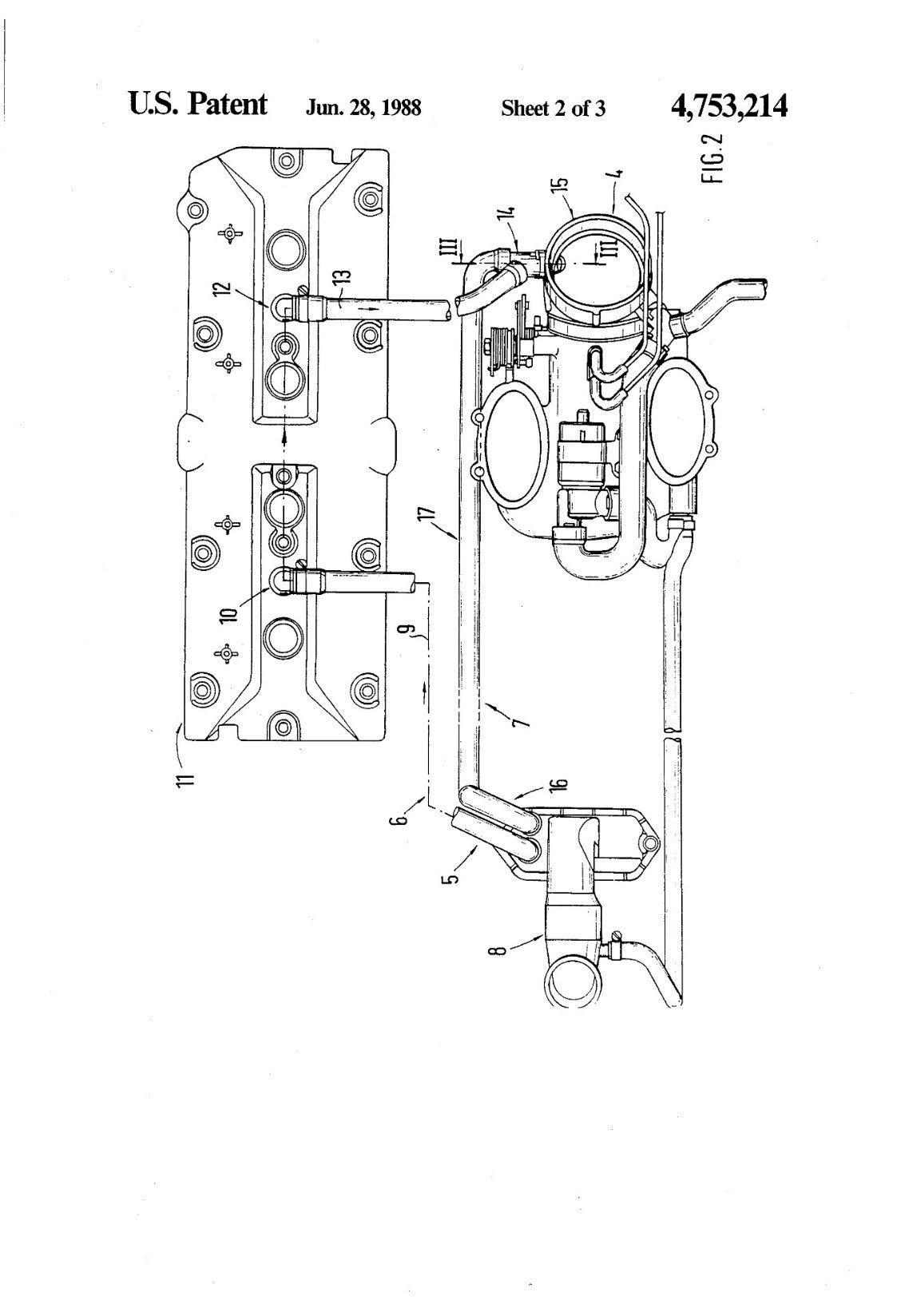
The post-1987 Porsche 928 models have had a number of different kinds of crankcase breather systems installed from the factory. The original conceptual design is described in the US Patent 4,753,214. Figure below is sourced from the patent documents:
There are a number of important features in this original concept....
I think your description of the concept, evolution and issues with the stock breather system is excellent - I very much agree with your assessment. I also agree there were other issues than just the breather changes that affected the GTS results.
I'm on a rather different solution path - but I do appreciate your rationale for the head balance plumbing, something to think about. I definitely agree that ensuring flows from the heads to the pan under all conditions is super important as is avoiding situations that allow significant pressurization (e.g. any positive feedback loop) of the crank - since that also causes excess entrainment that makes separation much more difficult.
Seems like you have a plan that has mostly come together now. Keep posting!
I think this problem needs the approach of a judoka. Don't fight any issue head on, instead try to use the problem forces against themselves.
Don't try to pick up vapor from the front of the engine when you're decelerating - the deceleration force will throw the oil to the front of the engine. When you're decelerating, pick up from the back of the engine instead.
Don't try to pick up vapor from the back of the engine when you're accelerating -- the acceleration force will throw the oil to the back of the engine. When you're accelerating, pick up vapor from the front.
When the engine has a problem draining oil from the heads to the sump, don't pick up vapor from the heads and make the oil flow fight the gas flow. Instead, pick up vapor from the crank case, using the gas flow to assist the oil drain.
Don't try to pick up more than a couple of CFM from the valve-cover ports with a shroud, or else the air speed in the shroud tube will be so fast that oil will not separate and the valve-cover port will puke oil. You'll get more air and less oil if you use a conservatively sized restrictor in those head ports.
Etc.
I think all those principles apply even if you use vacuum pump to assist the evacuation, and whether you're normally aspirated or boosted in the manifold.
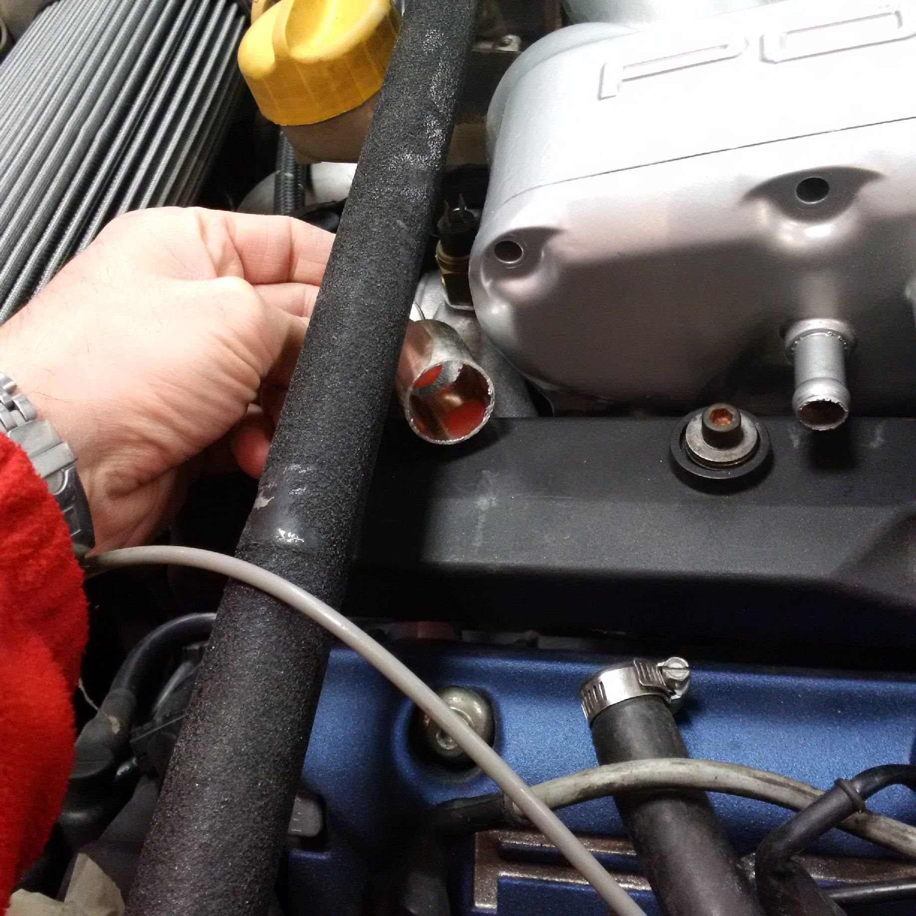
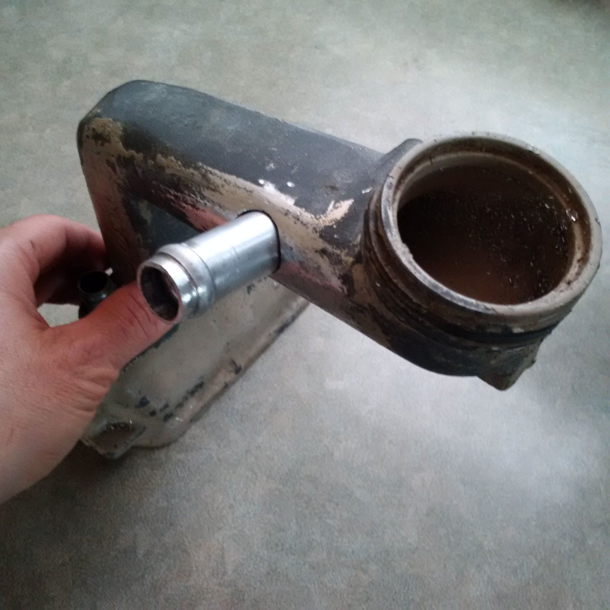
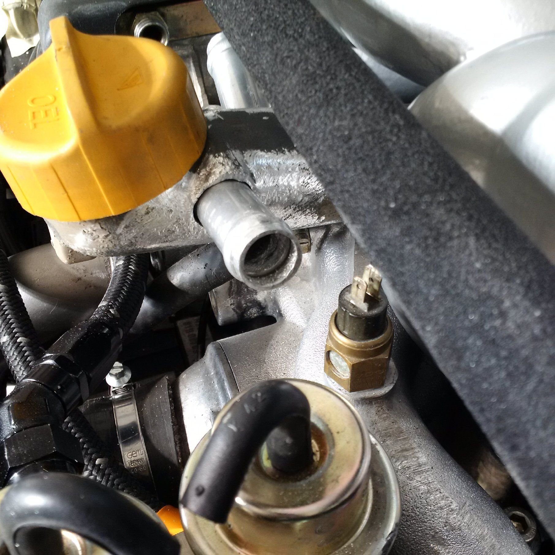
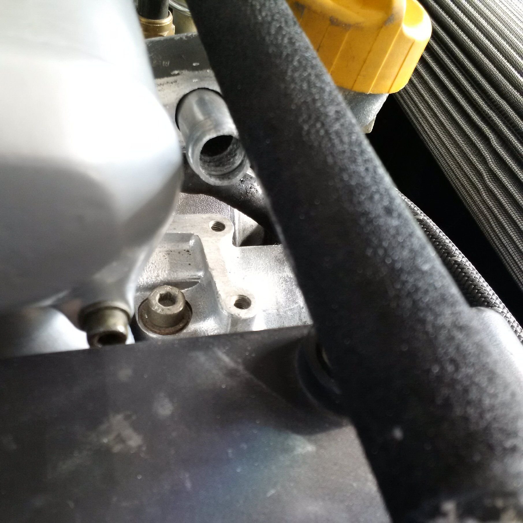
Breather ports fitted and ready to go to be welded
This is (surprise!) another very space constrained situation. We need to pull two .75" ports from the oil filler neck, from locations that work well considering the acceleration forces that the car sees, including gravity. These need to have sufficient clearance to the cross brace. In addition, they and associated hoses have to clear the extra fuel dampers, fuel rails, hoses, fittings, intake manifold, etc.
Here's John's "final answer" ready to go to welding, pros can do that since it's magnesium alloy. The ports stick 3mm inside the filler neck such that any cornering forces are unlikely to push any of the residual oil in the neck into these ports. The oil will instead flow on the filler neck wall.
Why don't you just tap the filler neck holes and cut some threads on the vent pipes? That's what I did with mine 10 years ago when I built my SC setup. I have two vent ports on the same spot as yours and another one (eyeball engineering guessing) at the top of the filler cap.
Why don't you just tap the filler neck holes and cut some threads on the vent pipes? That's what I did with mine 10 years ago when I built my SC setup. I have two vent ports on the same spot as yours and another one (eyeball engineering guessing) at the top of the filler cap.
For this filler neck and vent placement, the casting is not thick enough for just threads. These are 0.75" OD plugs, so they need some depth to seat securely just on threads. What size were yours?
If there would be a single pipe going thru two holes, then it would be more secure no matter what method you use. But the real estate concerns are such that we can't have them aligned.
If you use an NPT tap it will deal with some hi temp thread sealant like loctite etc. I also used an NPT tap to scavenge with my vacuum pump from the filler neck..
If you use an NPT tap it will deal with some hi temp thread sealant like loctite etc. I also used an NPT tap to scavenge with my vacuum pump from the filler neck..
What size?
We briefly considered various options, including interference fit heating the neck, thread + epoxy etc. but ended up with welding being the most reliable method. That was our judgment, others may come to their different conclusions.
I don't remember the size, maybe 1/2 each. The neck has more than enough material to tap it for an NTP thread and it will hold the vent pipes, even if it's as big as you guys are using. These are only there to vent air with hardly any air pressure in them. Now if this was some high pressure coolant or oil line then yes, the filler neck is too thin. But not for the crank vents.
We briefly considered various options, including interference fit heating the neck, thread + epoxy etc. but ended up with welding being the most reliable method. That was our judgment, others may come to their different conclusions.
I did 1 - 1" NPT on the underside of the filler neck. I believe you could get one 3/4 NPT on each side of the neck. An alternative is to use one 1" on the underside and do a T union to 2 individual 3/4" NPT fittings..
I used loctite and it's fine on my setup. Remember NPT is a tapered fit so it will seal quite effectively.
I also used aluminum NPT fittings so the temp expansion would be closer than with steel fittings and an aluminum filler neck.

 03-22-2016, 07:09 AM