
Twin Turbo 928 fixed and back out there terrorizing the streets!
 09-13-2010, 10:00 PM
#406
Drifting
Trust me, it spools the turbo right now anyway. When it's enabled I wot the car and it continues to pull timing out to hold the engine down to 6000 rpm. The engine is a 2.3 liter and spools a GT3076R to 28 psi in probably 1 second. Also, since you are wot the whole time, the blow off valve (map based) isn't active anyway. Technically it would work best at about 13.5:1, but spool time isn't an issue at all and I've already broken my header once tuning it.
 09-13-2010, 10:51 PM
#407
Supercharged
Rennlist Member
Rennlist Member
Join Date: May 2002
Location: Back in Michigan - Full time!
Posts: 18,925
Likes: 0
Received 60 Likes
on
34 Posts
That will work, if your system is completely symmetric. Since my trubos are clocked differently, it's not guaranteed to work for me. Using one MAF in a dual system also removes some of the incredible robustness of the MAF system to almost any changes or faults in the physical engine.
If you ever get the urge to add another MAF to make your system symmetric, the MAF signal averaging circuit components are less than $20 I recall.
If you ever get the urge to add another MAF to make your system symmetric, the MAF signal averaging circuit components are less than $20 I recall.

But I can see where averaging the MAF input might be a good thing. If you have any info on that circuitry, I'd be interested in having it in my back pocket... just in case.
09-14-2010, 12:03 AM
#408
Nordschleife Master
Thread Starter
I also have (****ty, poorly written) c code for Arduino to take any two MAFs and use their signals to emulate any single MAF. It's using three tables from that one can source from the MAF spec sheets.
By the way, whoever invented the LH and EZK mounting bracket is evil.
09-14-2010, 12:38 AM
#409
Burning Brakes

Join Date: Oct 2008
Location: Palo Alto, CA
Posts: 972
Likes: 0
Received 0 Likes
on
0 Posts
Oh Tuomo, I love arduino! That's how I'm driving my VGT actuator. Also I'm definitely going to use an adaptation of my code to run a pressure balancer on a chemistry reaction vessel I've built for work. Should be pretty neat.
09-18-2010, 04:57 PM
#410
Nordschleife Master
Thread Starter
Ok, now is the time to install the belly pans. Yes, it's the similar type of pain in the but as with the stock car, except squared.
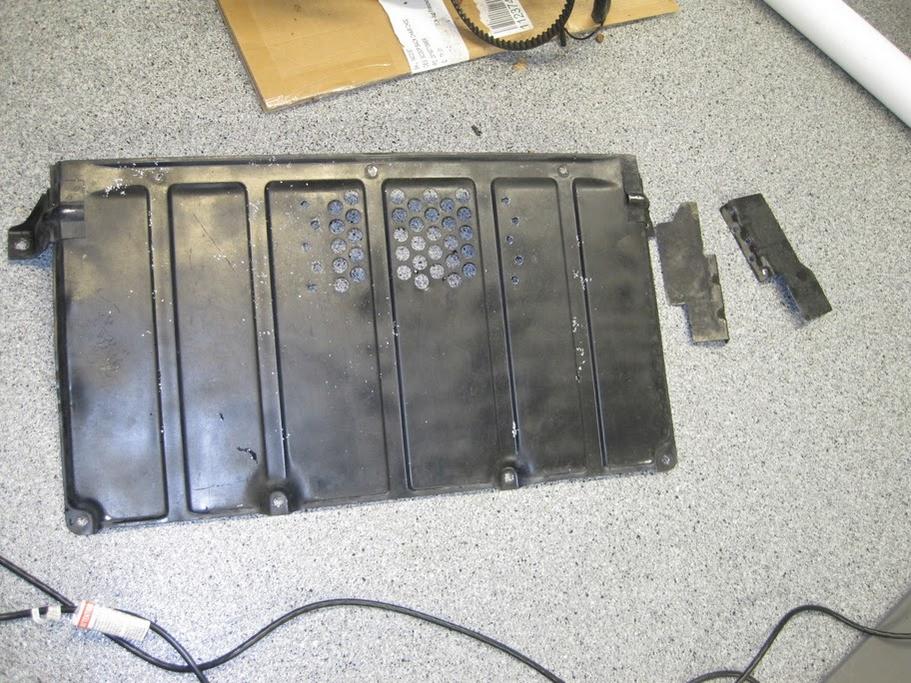
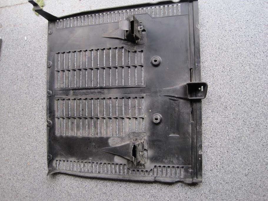
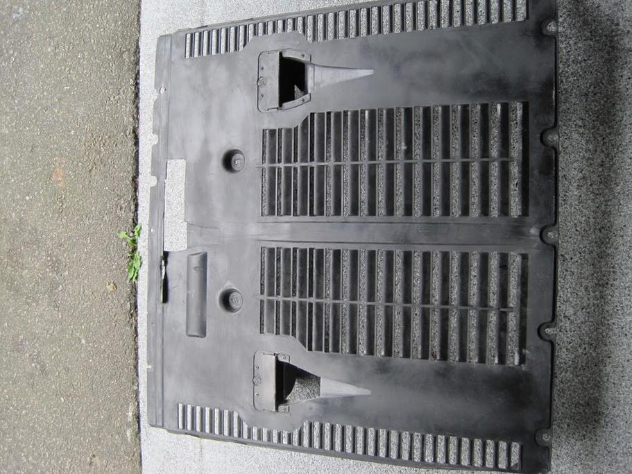
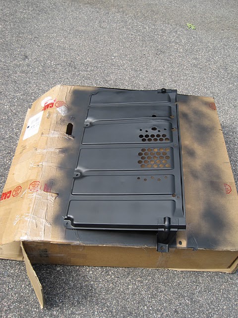
First, time to modify the rear pan. It has to fit the auxiliary oil pump studs and the turbocharger oil sump drain plugs. Also, the guiding vanes in the middle have to go:
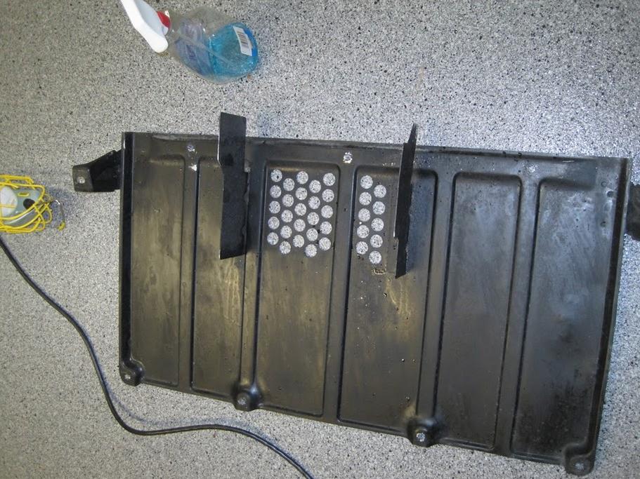
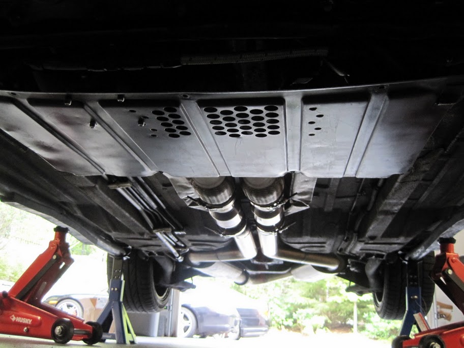
Installed! The only problem is that now the oil pump noise vibration harshness is resonated all over the place by the rear pan. The pump which earlier was barely audible is now as loud as... well... the fuel pump.
I'll have to pull the rear pump the nth time, expand the oil pump stud holes, put grommets in, and coat the inside with spectrum. Another morning there.
There's the front pan as well. This was more of a challenge. Had to cut some refliefs for the oil lines and for the extra-long sandwiched oil filter.
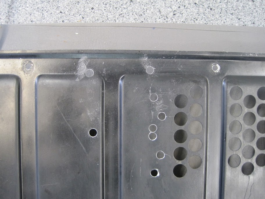
Before:
After:
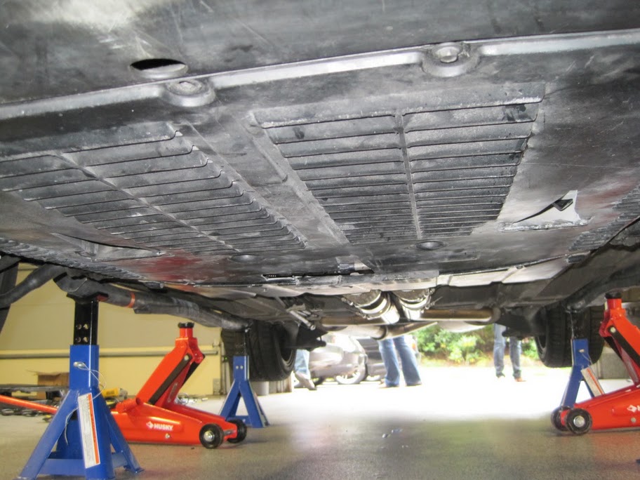
Now installed.
The oil pump NVH is so bad, though, that I get to repeat it all tomorrow. Closed cell foam, spectrum coating, little inconel heatshield and all that jazz.
First, time to modify the rear pan. It has to fit the auxiliary oil pump studs and the turbocharger oil sump drain plugs. Also, the guiding vanes in the middle have to go:
Installed! The only problem is that now the oil pump noise vibration harshness is resonated all over the place by the rear pan. The pump which earlier was barely audible is now as loud as... well... the fuel pump.
I'll have to pull the rear pump the nth time, expand the oil pump stud holes, put grommets in, and coat the inside with spectrum. Another morning there.
There's the front pan as well. This was more of a challenge. Had to cut some refliefs for the oil lines and for the extra-long sandwiched oil filter.
Before:
After:
Now installed.
The oil pump NVH is so bad, though, that I get to repeat it all tomorrow. Closed cell foam, spectrum coating, little inconel heatshield and all that jazz.
Last edited by ptuomov; 09-18-2010 at 07:28 PM.
09-19-2010, 07:10 PM
#411
Nordschleife Master
Thread Starter
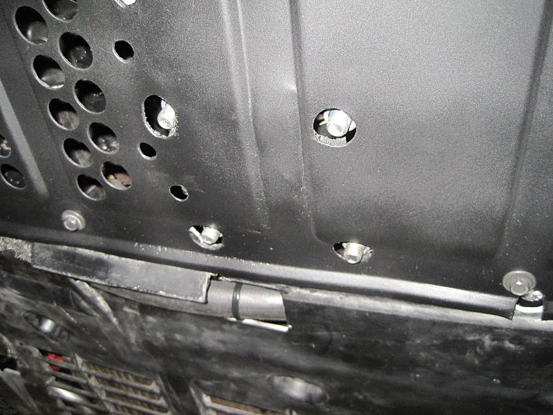
The aux oil pump was loud to start with, and become mega-loud with the belly pans installed. Late last night, I pulled the rear pan and coated it with Spectrum. I gave it another coating layer early this morning. Then, I increased the sizes of the holes for the oil pump studs. Added some closed-cell foam under the pump cooling ribs. Finally, put a hi-temp low-gloss engine paint on it.
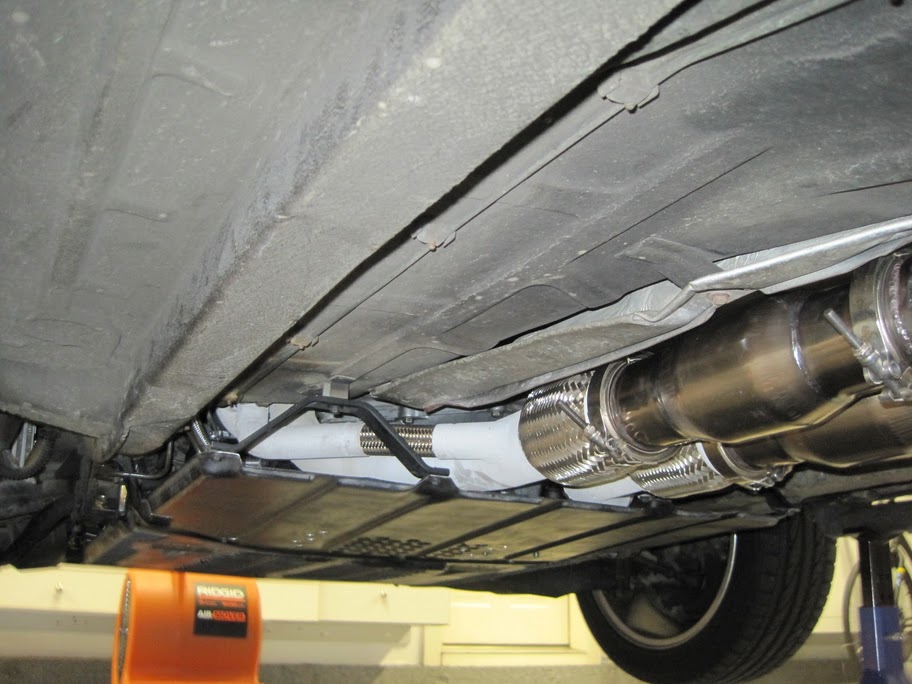
This didn't help. The aux oil pump is still louder than before. So I went back under the car with my stethoscope and found that the front belly pan is vibrating as well. Turns out that the stainless steel braided oil lines from the pump were touching the front belly pan.
A digression. These ss braided lines are a NVH nightmare! No wonder you don't see them on production cars where they have real engineers solving problems. It's just us dumb red-neck hot roddedrs who pay good money for these shiny pieces of S. Oh well.
So I made a sleeve from regular rubber hose around the ss braided line and reoriented the fitting a bit. This isolates the turbo oil lines from the belly pan. Now, the pump noise is merely slight annoying buzz, as before the belly pan install. A relative victory.
09-19-2010, 08:20 PM
#412

I can understand your frustration Tuomo. I hear things others do not in automobiles, and I am always chasing vibrations and noises so as to get as quiet for each car as possible.
09-25-2010, 10:35 PM
#413
Nordschleife Master
Thread Starter
For the last couple of days, I've been trying to get the fuel pump to play with the fuel pump controller. I am trying to use the Aeromotive 16306 pump controller, because the box that it's in is much prettier than my Arduino plastic box. Not much luck. I have a couple of tricks left in my sleeve, but they have to wait until tomorrow.
The car functions well, including the fuel system. The only reason why I am going thru the trouble here is that I want to lower the pump noise further at low rpms. This in anticipation of getting better muffling to the exhaust.
Part of me wants to give up. Part of me says "No effin' way."
Last edited by ptuomov; 09-28-2010 at 04:44 PM.
09-26-2010, 01:58 PM
#414
Nordschleife Master
Thread Starter
Here's the Aeromotive controller as installed. I think the install looks nice. The downer is that it doesn't work.
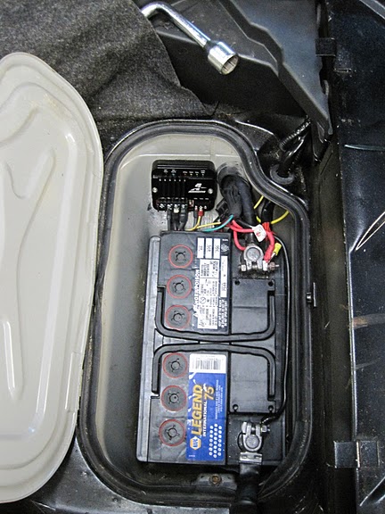
It not working didn't come as a complete surprise, given the trouble I've been having with aftermarket electrical parts, so I wired in a way that by switching one wire connection that car runs as if the controller woudln't be there. This is how it's wired in the photo.
I solved a couple of problems related to the required load on various connections, floating postive vs. negative pins, etc. Where I finally hit the wall was finding out that the Aeromotive controller sends out 100 Hz signal and the Fuelab Prodigy needs 500-1500 Hz to work.
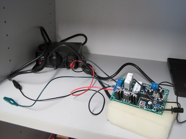
I can get the pump to do my bidding using my test pwm generator, which is not nearly as aesthetically pleasing as the Aeromotive controller. I'll either have to open the Aeromotive "billet" box and figure out how to multiply the frequency by 10x or find a nice box for one of my home grown controllers.
On other news, next time the fuel system comes off (and it seems to be coming off about once a month), I'll probably install this new in-tank fuel pickup. It's my variation on the pickup that comes with John's twin turbo kit.
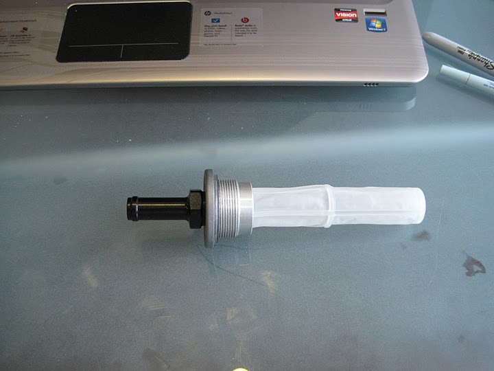
If someone is interested in getting a true -10AN hose barb out of the stock tank, I made have an extra piece. I'll sell it at cost if goes to good home.
It not working didn't come as a complete surprise, given the trouble I've been having with aftermarket electrical parts, so I wired in a way that by switching one wire connection that car runs as if the controller woudln't be there. This is how it's wired in the photo.
I solved a couple of problems related to the required load on various connections, floating postive vs. negative pins, etc. Where I finally hit the wall was finding out that the Aeromotive controller sends out 100 Hz signal and the Fuelab Prodigy needs 500-1500 Hz to work.
I can get the pump to do my bidding using my test pwm generator, which is not nearly as aesthetically pleasing as the Aeromotive controller. I'll either have to open the Aeromotive "billet" box and figure out how to multiply the frequency by 10x or find a nice box for one of my home grown controllers.
On other news, next time the fuel system comes off (and it seems to be coming off about once a month), I'll probably install this new in-tank fuel pickup. It's my variation on the pickup that comes with John's twin turbo kit.
If someone is interested in getting a true -10AN hose barb out of the stock tank, I made have an extra piece. I'll sell it at cost if goes to good home.
Last edited by ptuomov; 09-28-2010 at 04:45 PM.
09-26-2010, 07:16 PM
#416
Tuomo -
PWM multiplier board:
http://www.jbperf.com/pwm_converter/index.html
PWM multiplier board:
http://www.jbperf.com/pwm_converter/index.html
Following discussions on the MS2/extra forum, I have designed a board which takes a PWM signal (such as the output for FIDLE or boost control the with MS2/extra code) and multiplies the frequency while keeping the same duty cycle without losing any precision. This allows people to control a device (solenoid, valve, motor) that requires a frequency higher than what the code can do or use a lower frequency in the code (with the associated higher resolution) and have the device work at a higher frequency.
The CPU on the board will read the PWM signal and keep the same duty cycle but multiply the frequency. It has been tested with the MS2/extra code from 11.1Hz to 78Hz with good results but it will work from about 8Hz to more than 300Hz. The output frequency can be chosen by setting jumpers and the resulting frequency multipliers can be 2, 4, 8, 16, 32, 64, 128, and 256. At an input frequency of 78Hz from the MS2 and a multiplier of 256, the PWM converter CPU will generate a 19968Hz PWM signal with a 0.25% resolution. So it's safe to say that any usable combination of input frequency and multiplier will not lose any precision. Also, the PWM duty cycle (and frequency) is updated for every cycle of the input signal so at 11.1Hz the output duty cycle is updated 11.1 times per second and at 78Hz the update is done 78 times a second. And the input is read with a 16-bit timer with 12 to 16 effective bits depending on the input frequency.
The board is 1"x 1", has 2 mounting holes and is shown at the top of the page. The kit includes all the components as shown below plus a TIP122 and mounting kit with insulator which are not in the picture. The kit includes a socket for the processor but its use is optional since it makes the completed board taller. Additional care must taken, if not using the socket, when soldering the CPU to the board since it is more sensitive to heat and static.
09-26-2010, 07:47 PM
#417
Nordschleife Master
Thread Starter
Interesting.
I do have two home-made or home-assembled boards that could drive the pump on their own without the Aeromotive controller. The only reason why I am trying to get the Aeromotive controller to work is that the "billet" case looks good. The board in your link is 1" x 1" and will not fit as an add-on inside the Aeromotive case. Also, it only works for 0-5w voltage, not 0-12V. If I have to find a separate case for it, I might just as well find a case for either of my home-made controllers and ditch the whole Aeromotive thing. I ordered it anyway! ;-)
The plan A now is to open the Aeromotive controller and figure out if there's something simple that I can do, like changing a resistor and/or a capacitor and get the thing to run at 1 kHz. We'll have to see.
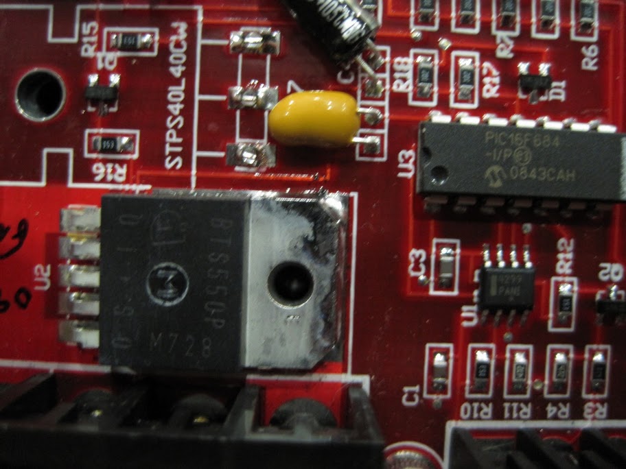
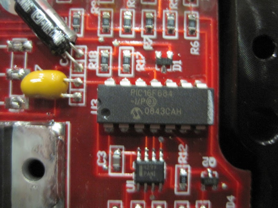
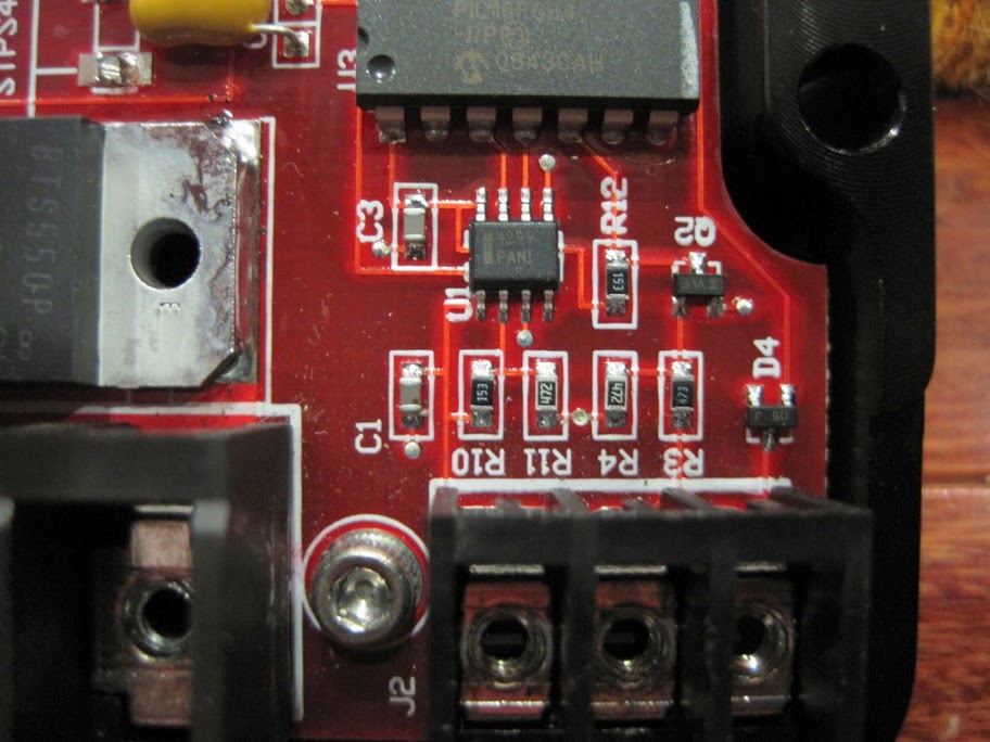
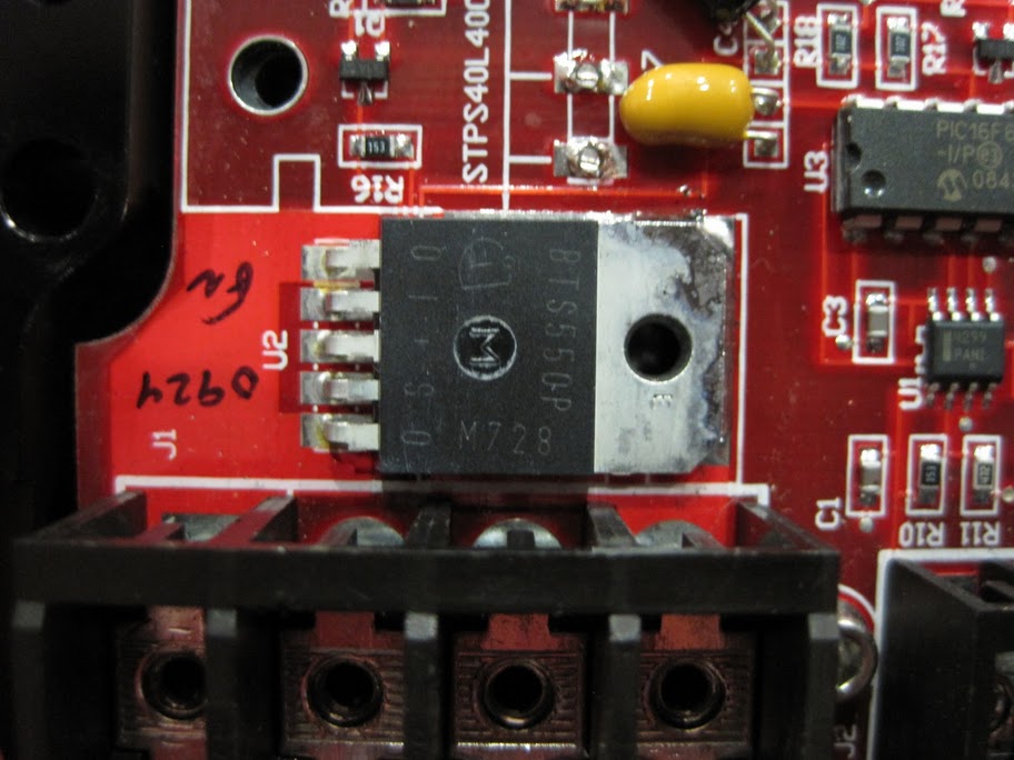
Update:
Here's what the Aeromotive controller looks like inside. That's PIC 16F684, which is flashable controller I think. They should be able to make a 1 kHz version of their source code, but I have a snowball's chance in hell of hacking it on my own.
I do have two home-made or home-assembled boards that could drive the pump on their own without the Aeromotive controller. The only reason why I am trying to get the Aeromotive controller to work is that the "billet" case looks good. The board in your link is 1" x 1" and will not fit as an add-on inside the Aeromotive case. Also, it only works for 0-5w voltage, not 0-12V. If I have to find a separate case for it, I might just as well find a case for either of my home-made controllers and ditch the whole Aeromotive thing. I ordered it anyway! ;-)
The plan A now is to open the Aeromotive controller and figure out if there's something simple that I can do, like changing a resistor and/or a capacitor and get the thing to run at 1 kHz. We'll have to see.
Here's what the Aeromotive controller looks like inside. That's PIC 16F684, which is flashable controller I think. They should be able to make a 1 kHz version of their source code, but I have a snowball's chance in hell of hacking it on my own.
Last edited by ptuomov; 09-28-2010 at 04:46 PM.
10-05-2010, 10:34 PM
#418
Nordschleife Master
Thread Starter
I've been battling this fuel pump control problem, and it's progressing at about as smoothly as Iran's nuclear program. Stuff has happened, such as my multimeter giving up, that can only be explained by a stuxnet infection!
I needed an easy W in the middle, so when the last belly-pan screw came in the mail, I wrenched it on. Now the belly pans are all fastened. Made me feel better.
I have now successfully routed the rpm pulse signal, MAF voltage, and MAF ground to the back of the car. That's the good news. The bad news is that none of my controller "solutions" so far is working. For multiple reasons. There is no uncertainty about the fact that the controller problem will be solved, though, this has gotten personal.
It won't be solved by Aeromotive, however. Here's our email correspondence:
No response.
No response?!? I've lived in the US for 15 years now. It's not my experience that when I ask someone here "how much?" that they don't answer anything, nothing. That's Un-American, it's Un-American not to have a number!
I needed an easy W in the middle, so when the last belly-pan screw came in the mail, I wrenched it on. Now the belly pans are all fastened. Made me feel better.
I have now successfully routed the rpm pulse signal, MAF voltage, and MAF ground to the back of the car. That's the good news. The bad news is that none of my controller "solutions" so far is working. For multiple reasons. There is no uncertainty about the fact that the controller problem will be solved, though, this has gotten personal.
It won't be solved by Aeromotive, however. Here's our email correspondence:
Originally Posted by me
Here's a brief summary of my situation that we discussed over the phone.
My car has a Fuelab Prodigy pump. The pump has an internal controller, which takes a pwm signal as an input and uses that to determine the pump speed. The pwm signal input is only a logical signal, the pump doesn't draw any meaningful current from it. The pump turns on at 20% duty cycle and scales about linearly to 90% where the pump turns on full. According to the pump spec sheet, the pump requires the pwm signal to be in the 500-1500 Hz range. (I have verified with my function generator that pwm signals with frequency less than 400 hz do not work.)
I am trying to install your 16306 pump controller to provide logical pwm signal to the pump. In my setting, the pwm output from your controller would not provide the current to operate the pump but only a logic signal to the internal pump controller. This should all work well, except one problem. The pwm signal provided by your pump controller has 100 hz frequency and I would need ideally 1 kHz and minimally 500 Hz.
Can you customize your pump controller to increase the pwm signal frequency by 10x to 1 khz? I am thinking that this might be a very simple code change, perhaps just one parameter value. Although I am not very experienced with microcontrollers, I recognize the chip PIC 16F684 that you are using to generate the PWM signal. I am guessing that you might be able to change the pwm frequency by changing just one line of code.
The resolution of the duty cycle /pulse width doesn't need to be that fine and I am not drawing significant current from the pwm singal so I am not concerned about the side effects of increasing the frequency.
I understand that making this modification is going to cost me something.
Originally Posted by aeromotive tech
Yes, it’s not impossible to rewrite the code and reprogram our speed controller, however engineering says it will be notably cheaper for you to simple purchase an Aeromotive pump to go with your controller ;~)
Curiosity, It was my understanding that the Fuelab pump was designed to accept a variable voltage in order to change the speed of the pump. Why are you not taking advantage of that built-in workability?
Curiosity, It was my understanding that the Fuelab pump was designed to accept a variable voltage in order to change the speed of the pump. Why are you not taking advantage of that built-in workability?
Originally Posted by me
The first version of the Fuelab pump used analog 0-5v control voltage. They switched to pwm, probably because the pwm signal is less vulnerable to noise.
So how much for a custom controller with 1kHz pwm output?
So how much for a custom controller with 1kHz pwm output?
No response?!? I've lived in the US for 15 years now. It's not my experience that when I ask someone here "how much?" that they don't answer anything, nothing. That's Un-American, it's Un-American not to have a number!
