When you click on links to various merchants on this site and make a purchase, this can result in this site earning a commission. Affiliate programs and affiliations include, but are not limited to, the eBay Partner Network.
Tom- what kind of shape were your rods in when you took them out? Local dealer has seen several GT3 motors where the OEM rods started getting elliptical wear on rod ends (hole) which was very disconcerting to me. Getting mixed information about that from various technicians.
Tom- what kind of shape were your rods in when you took them out? Local dealer has seen several GT3 motors where the OEM rods started getting elliptical wear on rod ends (hole) which was very disconcerting to me. Getting mixed information about that from various technicians.
I didn't mic the big end. The engine was running perfectly on the track every shift between 8,000-8,200rpm. Never missed a beat, no rod knock sound, and held excellent oil pressure. Here's the thing, I do expect any Ti rod to go out of round at the big end a little bit and have some wear on the small end bushing with 80+ track hours. We rebuild a lot of GT3 and Cup engines at the shop to see that with enough tracks hours/over revs, some big end distortion is the norm. Of course the distortion can keep increasing and ultimately reach a point of failure but a little bit won't cause a catastrophic event. The heavier Chromoly H-beam or X-beam rods probably won't distort at under 500hp, but they do distort with 800+hp twin turbo engines with enough hard running time. A good machine shop can rebuild Ti rods to factory big end spec and re-bush the small end(the machine shops called this procedure "re-sizing" the rods). PMNA recommends new rods when they do rebuilds since they expect the rods to be a consumable. Anyway, I put my 3.6 Ti rod up for sale in the classifieds, I expect the buyer to have a machine shop go through them before using them, not just mine rods, ANY used rods, since some distortion is a byproduct of hard driving/track driving.
__________________
PCA National Instructor
TPC Racing stats:
2023 Porsche Sprint Challenge 992 Cup Am Champion
2023 Porsche Sprint Challenge GT4 Pro-Am Team Champion
2022 Porsche Sprint Challenge 992 Cup & 991 Cup Champion
2020 IMSA GT3 Cup Challenge 2nd Championship
2018 IMSA GT3 Cup Challenge 2nd Championship
2016 IMSA GT3 Cup Challenge Champion
2013 IMSA GT3 Cup Challenge Champion
2006 Rolex-24 @ Daytona GT Champion
2004 Grand-Am SGS Class Champion
For perspective, using US coins, a nickel coin weights 5.0 grams, a dime coin weights 2.27 grams, a penny can be 2.5 grams or 3.11 grams(apparently there are two versions of the US penny).
Just for fun this Sunday morning before I get down and dirty on the build, my scale is accurate within 0.1 gram to the published coin weights. So my engine's reciprocating assembly is imbalanced by the weight of a penny.
Tom- what kind of shape were your rods in when you took them out? Local dealer has seen several GT3 motors where the OEM rods started getting elliptical wear on rod ends (hole) which was very disconcerting to me. Getting mixed information about that from various technicians.
Originally Posted by Tom-TPC Racing
I didn't mic the big end. The engine was running perfectly on the track every shift between 8,000-8,200rpm. Never missed a beat, no rod knock sound, and held excellent oil pressure. Here's the thing, I do expect any Ti rod to go out of round at the big end a little bit and have some wear on the small end bushing with 80+ track hours. We rebuild a lot of GT3 and Cup engines at the shop to see that with enough tracks hours/over revs, some big end distortion is the norm. Of course the distortion can keep increasing and ultimately reach a point of failure but a little bit won't cause a catastrophic event. The heavier Chromoly H-beam or X-beam rods probably won't distort at under 500hp, but they do distort with 800+hp twin turbo engines with enough hard running time. A good machine shop can rebuild Ti rods to factory big end spec and re-bush the small end(the machine shops called this procedure "re-sizing" the rods). PMNA recommends new rods when they do rebuilds since they expect the rods to be a consumable. Anyway, I put my 3.6 Ti rod up for sale in the classifieds, I expect the buyer to have a machine shop go through them before using them, not just mine rods, ANY used rods, since some distortion is a byproduct of hard driving/track driving.
grrrmonster, since you brought this up it made me wished that I should have gone with the heavier but sturdier Pauter Chromolu rods!
The reason it troubles me: local dealer rebuilding engines with steel rods but engine was designed by Porsche for Ti rods. I've learned the hard and expensive way that the engineering an OEM puts into an engine has been carefully thought through. I don't want to use trail and error engineering in GT3 motor
The reason it troubles me: local dealer rebuilding engines with steel rods but engine was designed by Porsche for Ti rods. I've learned the hard and expensive way that the engineering an OEM puts into an engine has been carefully thought through. I don't want to use trail and error engineering in GT3 motor
I wouldn't be trouble it. Steel rods from Pauter and Carrillo for example, are excellent replacement choices and are race proven. We have a lot of customers running steel rods in race cars, as do many other engine builders I am sure. New Ti rods are nice if you don't mind the outrageous cost.
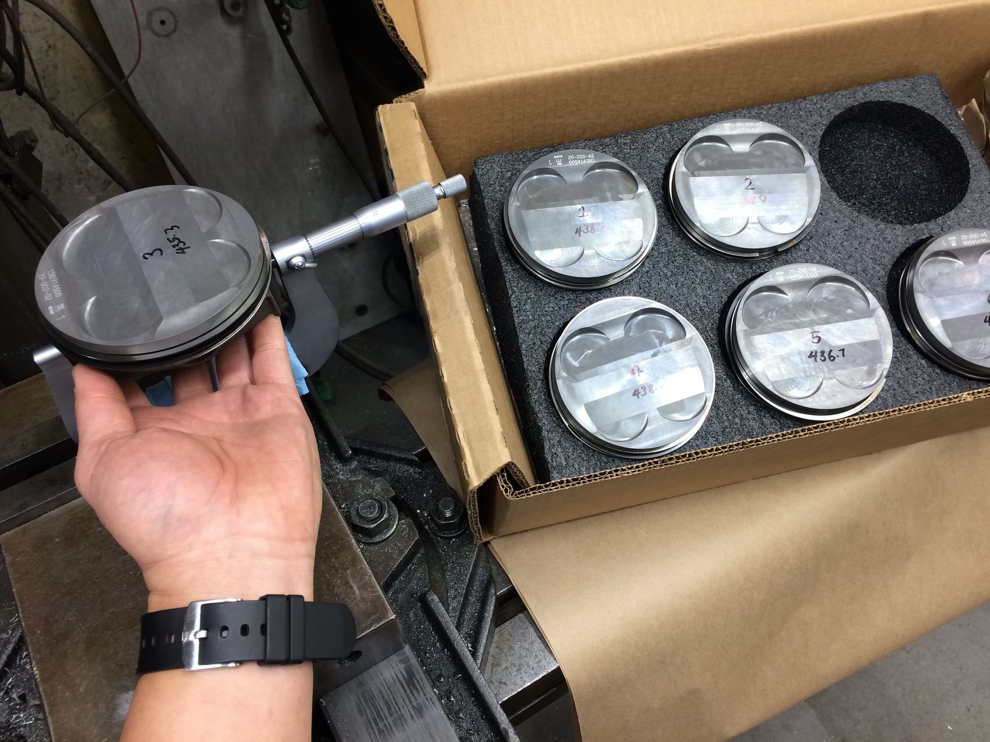
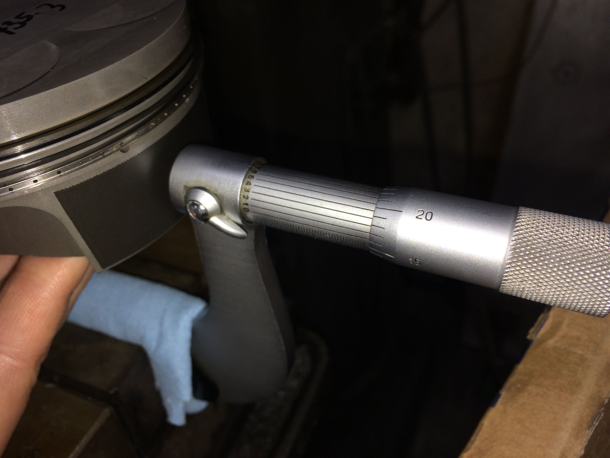
Measuring each piston's diameter with a micrometer.
They are all pretty close, within 0.001 inch, but I just wanted to know so I can do the next step.
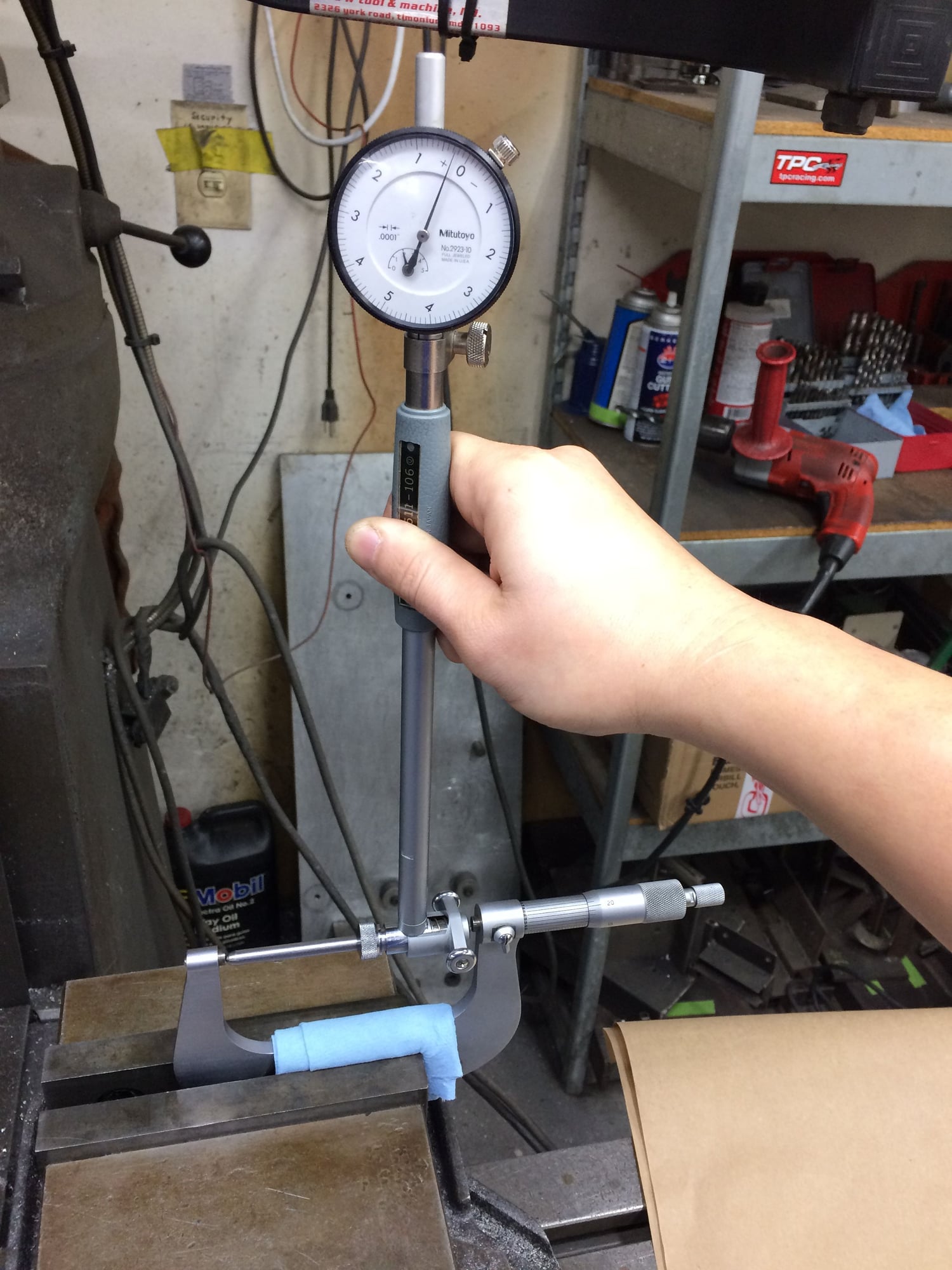
Taking each piston's measurement by a micrometer to zero a cylinder bore gauge.
With the cylinder bore gauge zero'ed to each piston's measurement I am checking each cylinder to best pair to a particular piston for the most uniform bore clearance.
I am done with tearing down, cleaning and prepping, and am eager to move on to assembling! But before we get started here, I wanted to clarify that I am Not a full time expert engine builder, in fact I am far from being one. With 23 years in the automotive industry, my mechanical background is I worked 7 years as a general-duty mechanic servicing and modifying American, European, and Japanese sports cars, following that I worked as a race team crewman and then worked up my way crew chief and than team manager. In more recent years I have been managing shop projects, specialty suspension product sales and support. I still get my hands dirty but I have mostly a desk job now. Basically I've been around high performance and race cars most of my adult life and have observed a number of engine builds by highly qualified builders here at the shop but I have only ever assembled 3 engines on my own, with all 3 being small block Chevy's. I am bringing this up in case there are any expert builders looking at these photos shaking their heads, I'm just a rookie assembling my own engine during off hours .
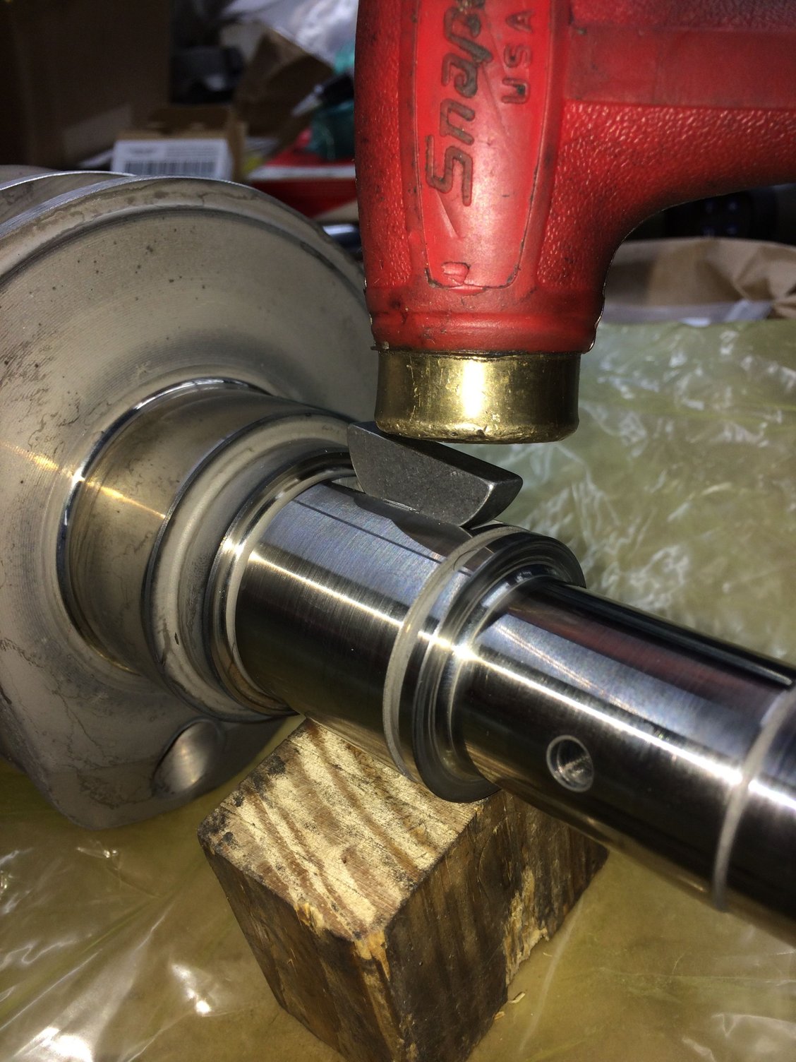
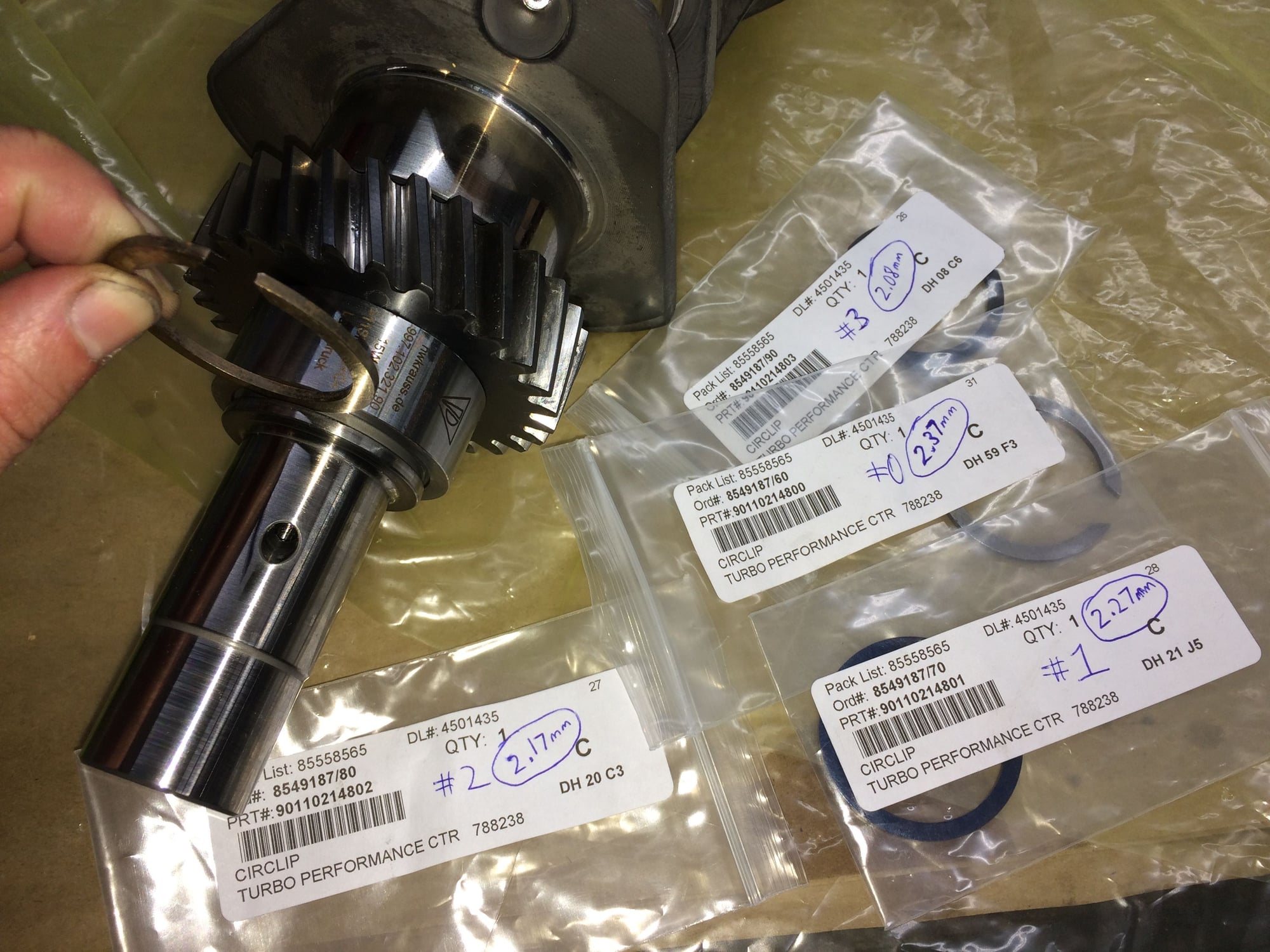
The new gear must be pressed onto the nose of the new 4.0 crankshaft.
Before pressing on the gear a woodruff key is tapped in "gently" with a brass hammer.
Once the gear and the spacer is pressed on, a circlip/shim locks it all in. There are four available circlip/shim thickness, had to buy all four to find the best fit. Circlip/shim #2 was perfect fit.
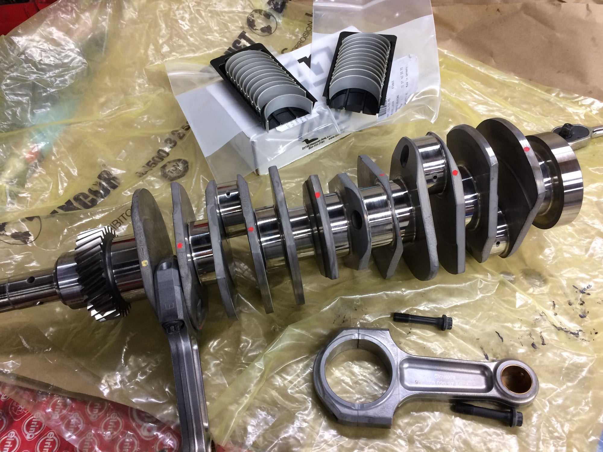
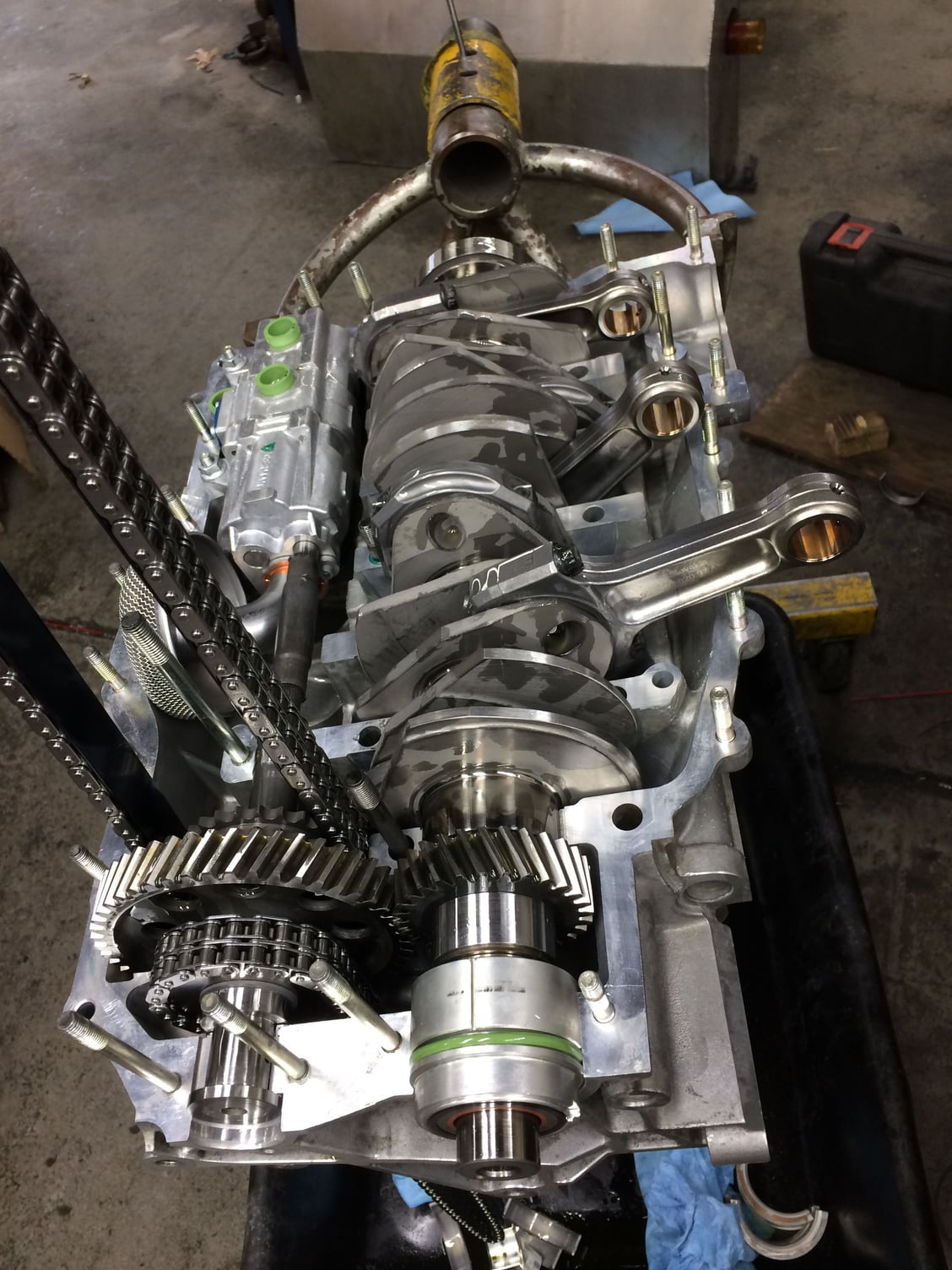
Putting the rods on the crankshaft. Looks simple but took a few hours to get from the first image to this. Oh, I didn't take photo of pressing the gear and spacer because I had my hands full keeping the crankshaft from falling off the vertical press.
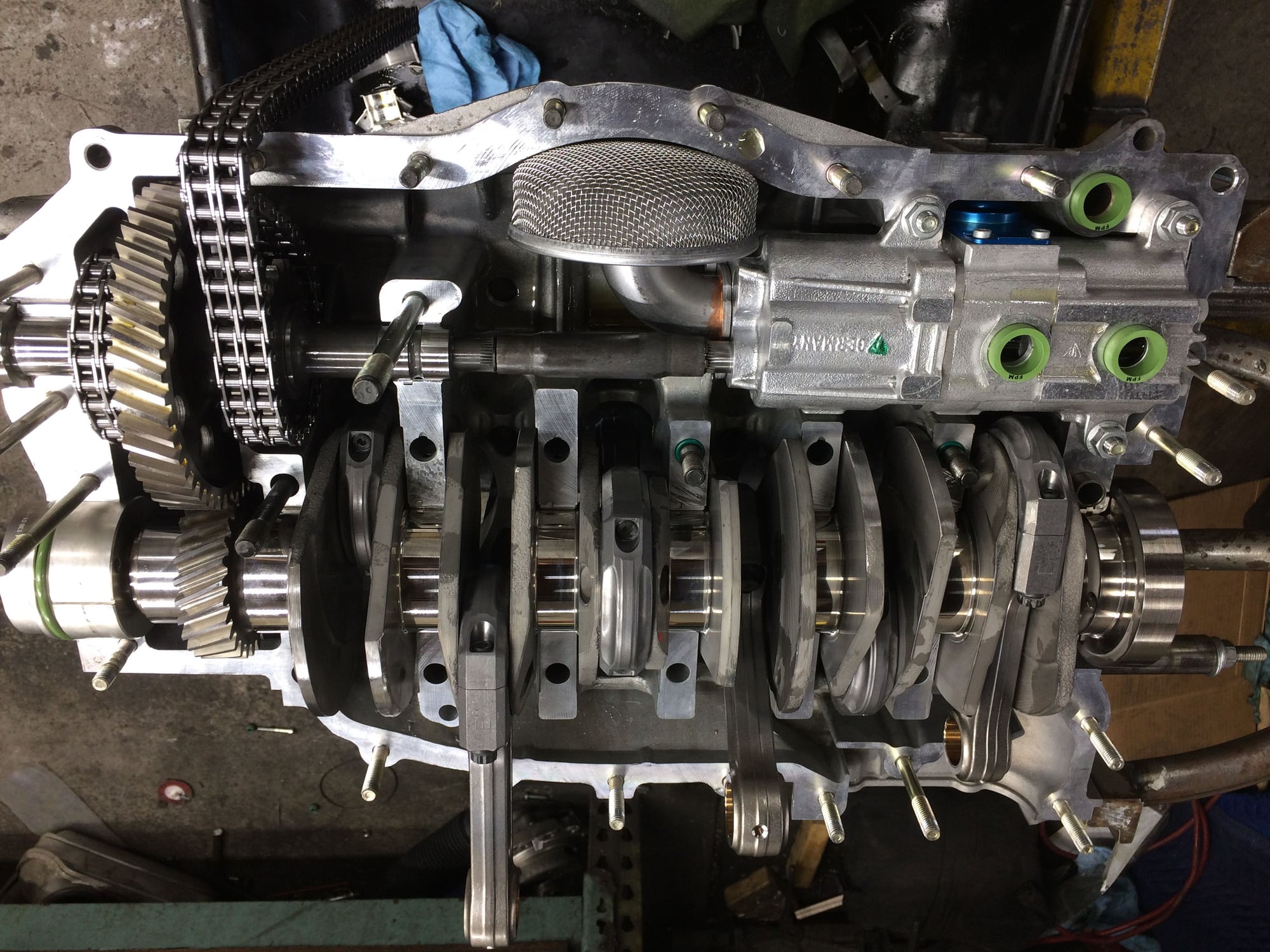
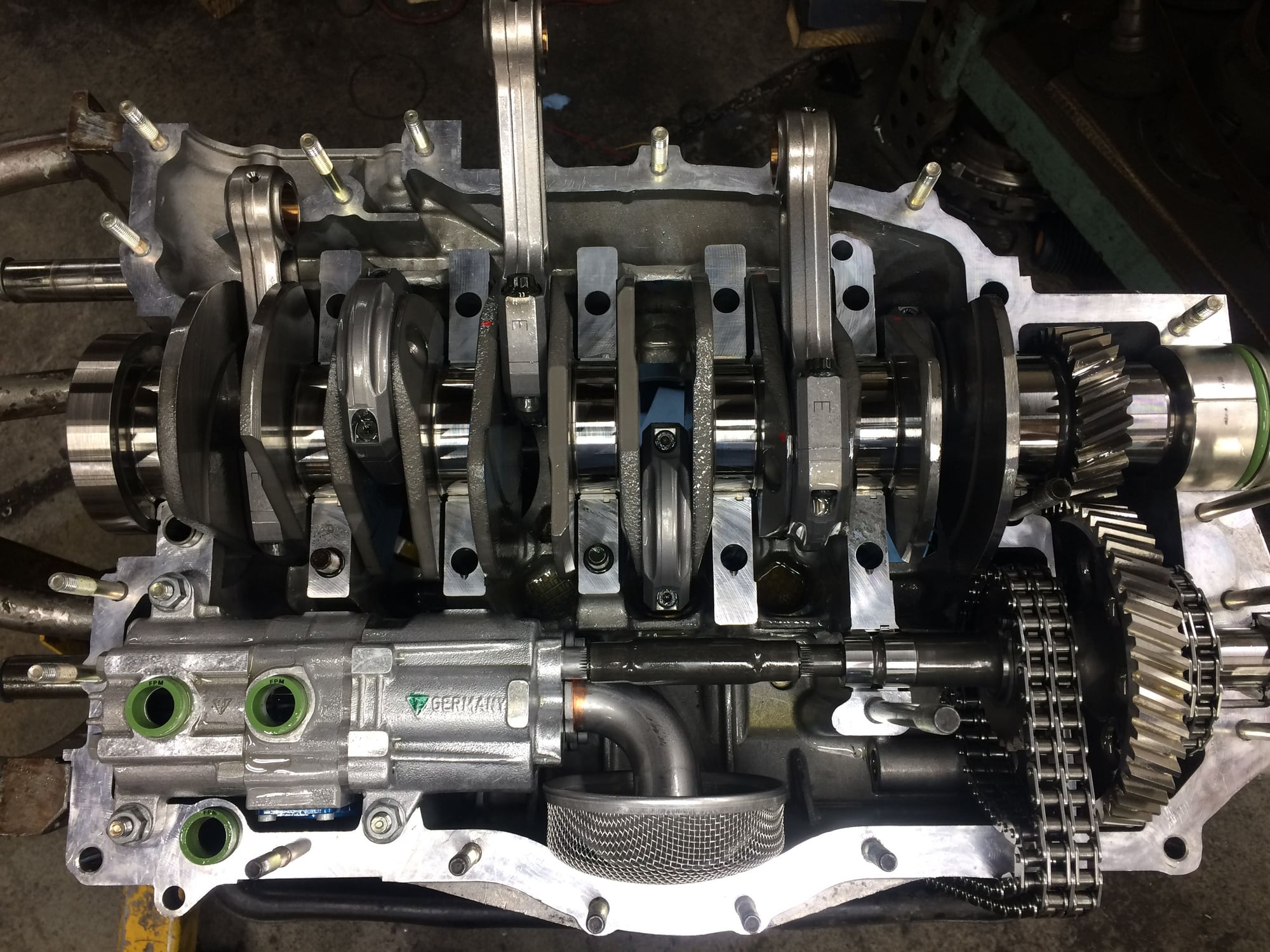
4.0 oil pump, intermediate shaft, crankshaft, rods, all in the half shell.
That's it a tight clearance!
Bottom case half ready.
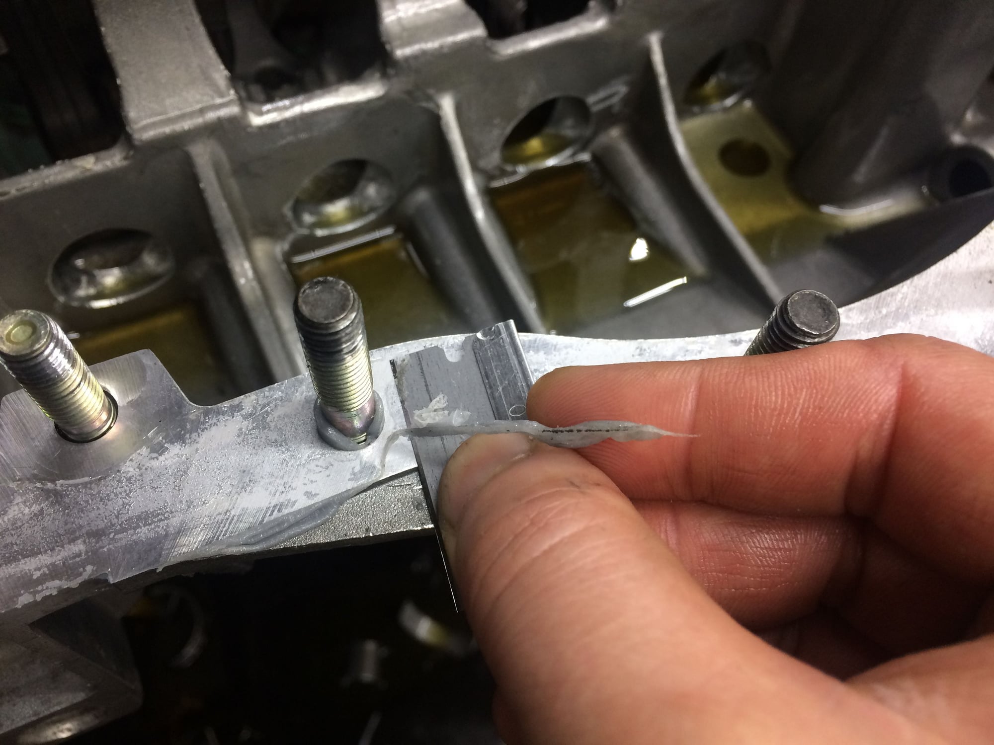
Carefully inserting the 24 case sealing rings in.
One minute you're feeling good, another minute a ring can fall into a hole or worst flying off like a rubber band into somewhere you don't want to be... fortunate only one fell and was able to fetch it out easily.
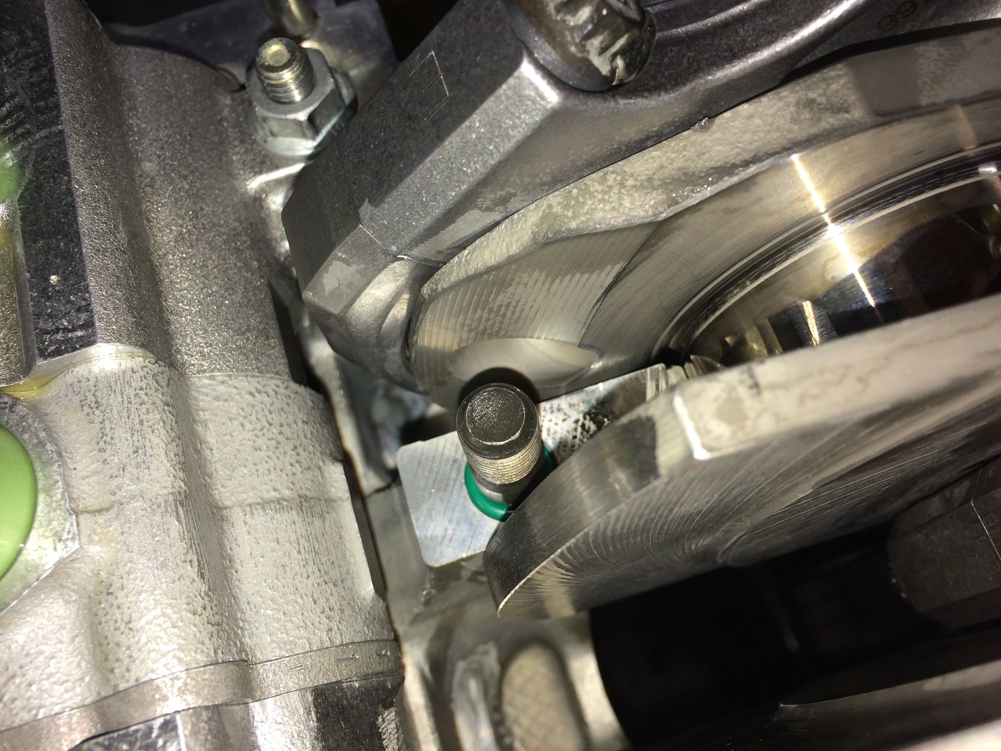
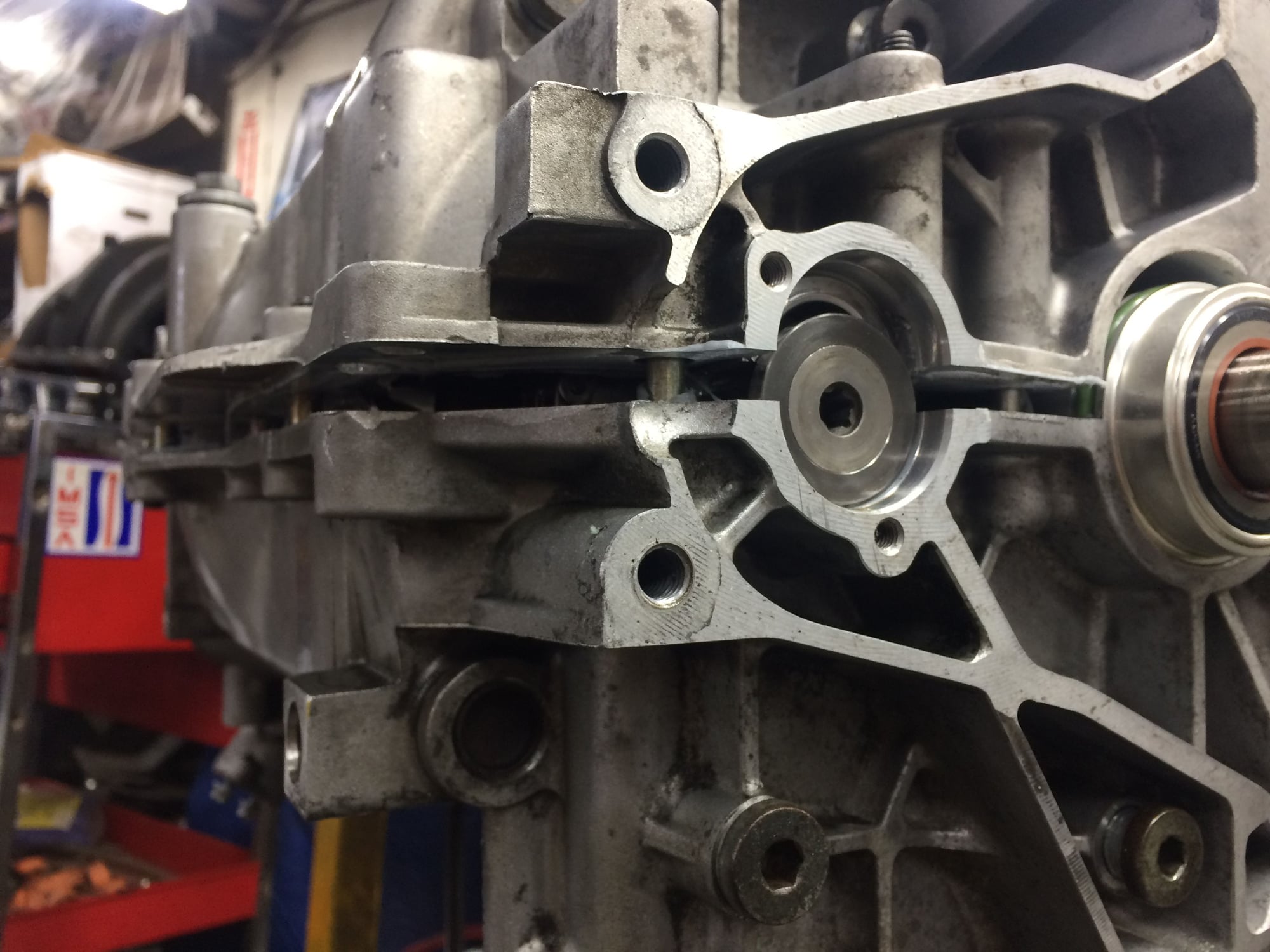
The chain doesn't have much room to slack. Maybe that's why the 4.0 chain guides I posted previously are shaped differently to guide the chain further from the 4.0 crankshaft counterweight.
Following up to the last post, the engine case halves are put together, sealed, and torque'd, making the engine's "bottom end" complete. I didn't take photos since I had my hands full and oily, and mainly my mind was focused on the assembly process. Since I didn't take photos I did find a very good youtube time-lapse video illustrating the work involved(the video shows assembly of 3.0 air-cooled bottom end, the torque specs are different than a water-cooled but the steps are the same, credit to good fellow who made and posted the youtube video!). Link-
So I was feeling good, accomplished, and energized that night after completing the bottom end. I was so energized that I couldn't fall asleep in bed and I started rethinking each step of the assembly. This is where the troubles begin...rethinking the steps I started to doubt myself on two things- One, I did a rookie move of using more sealant than necessary for overcompensation to prevent oil leak, Two, during the specific torque sequence process of the engine case bolts I got distracted by a phone call from a family member thinking it was an emergency but turned out it wasn't and then proceeded back skipping one bolt, which I checked and found the skipped bolt when I did an after-check but that disrupted the sequence.
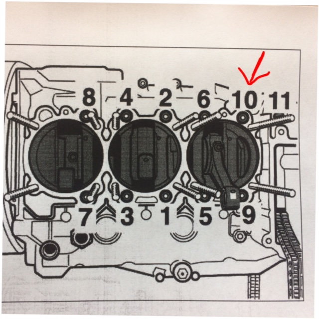
See image below of the torque sequence. After answering the phone call I skipped bolt #10 by accident, went from #9 to #11. I found out I missed #10 when I went through the sequence again to check. So I torque'd #10 and then went through the sequence one more time.
At the moment, I was glad to have found my mistake, and I think the engine would have been fine with torque'ing #10 after the first sequence and then followed by another sequence, BUT my personal doubts are haunting me, and more importantly knowing that I could have done it better and didn't will trouble me for as long as I live Its a lot of work to split the case halves, scrap off the sealant, clean, and prep everything again and possibly have something go wrong when redoing it all but I needed to redo this for my personal satisfaction.
The next evening after work, splitting the cases again. Look at that one-day old sealant...
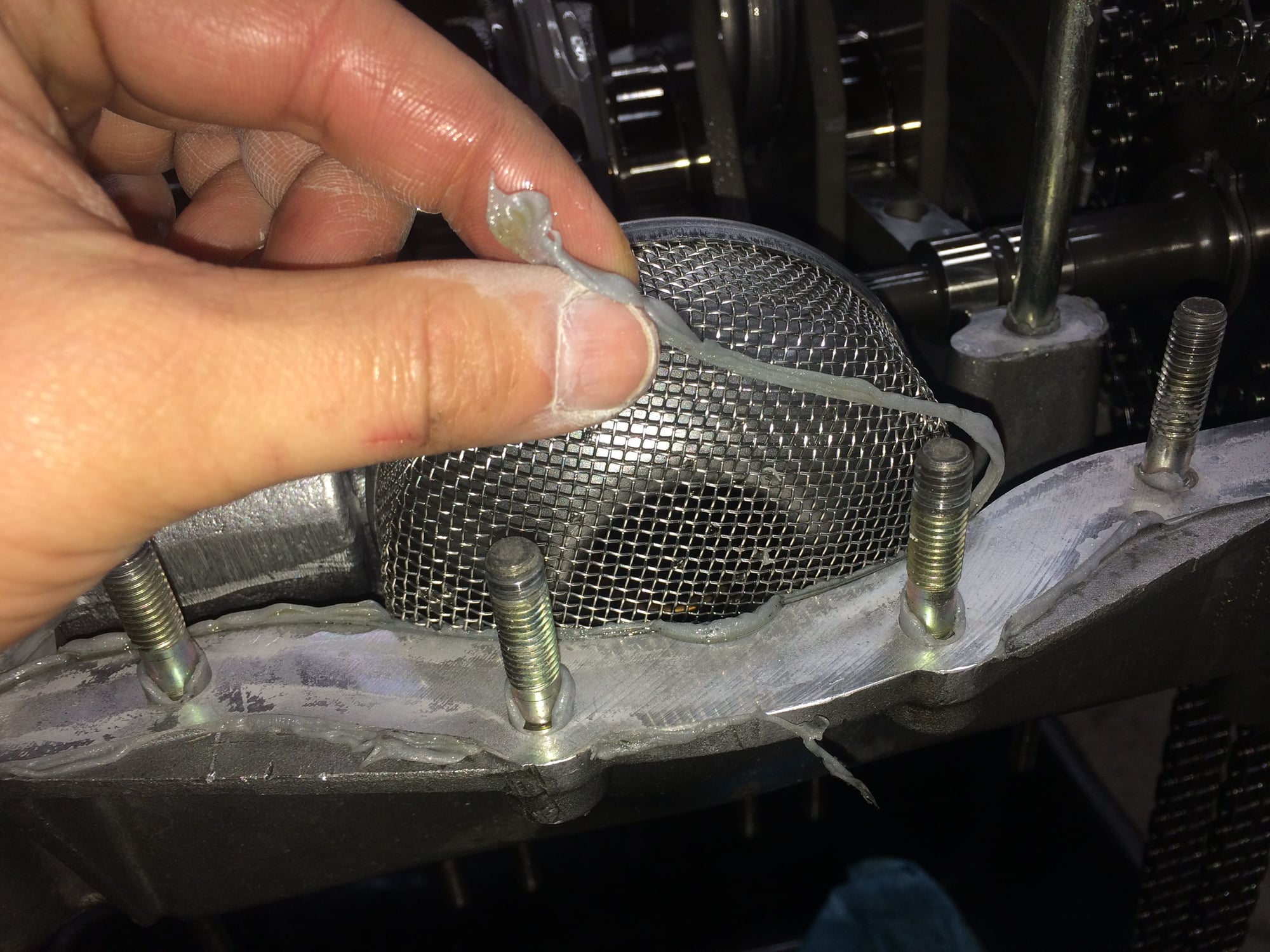
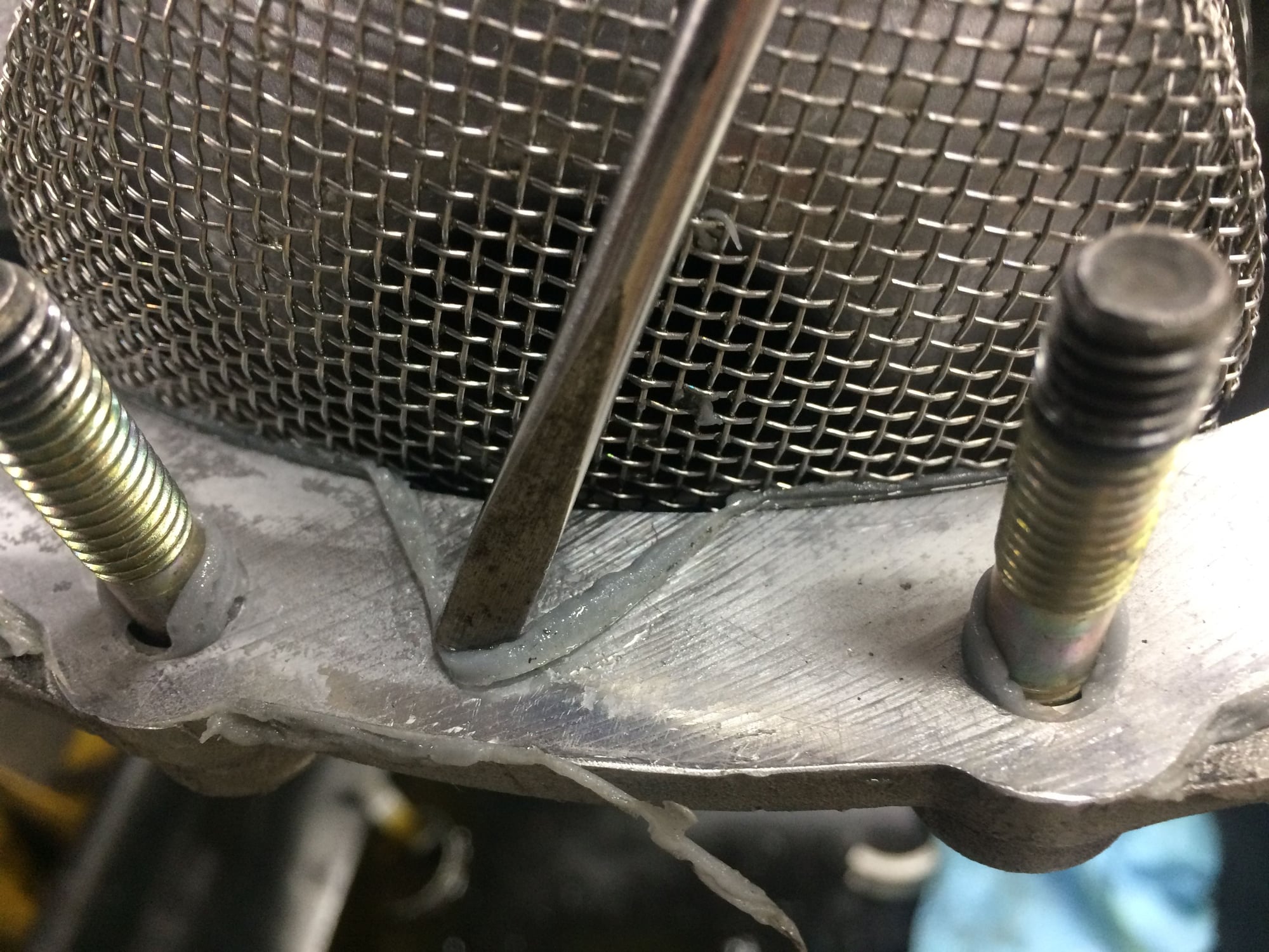
Glad I decided to redo, see that I used more sealant than necessary. These are rookie mistakes. Can read about it 100x and play these steps in my mind but when it comes to doing it for real these inexperienced mistakes can be easily made and not realized.
I asked engine experts, they said that while this is not ideal. the oil pump screen will prevent sucking in the excess sealant and even if small fragments go pass the screen the oil filter will trap the debris.
More scraping and cleaning. At least the one-day old sealant is easier to come off than 10 year old sealant.
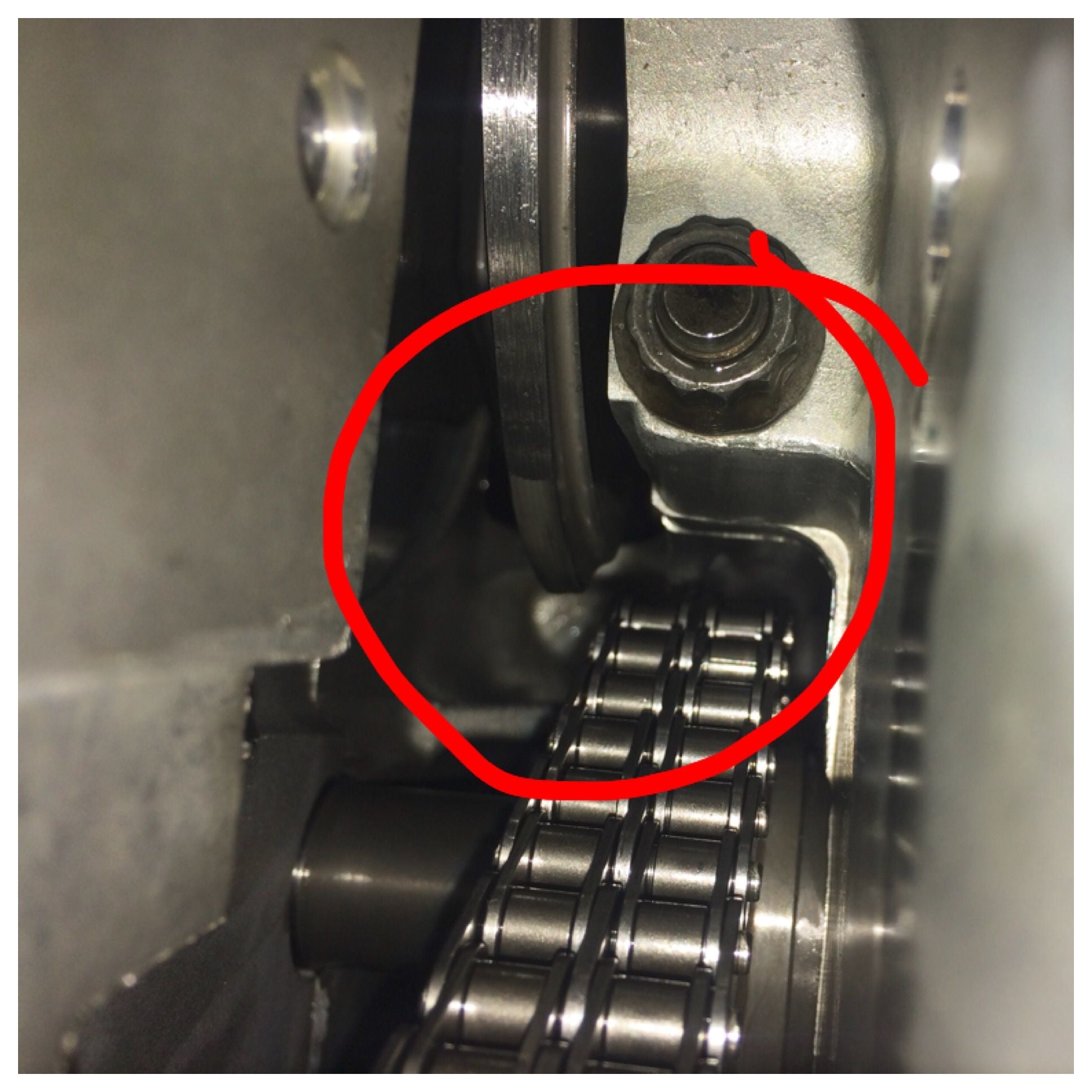
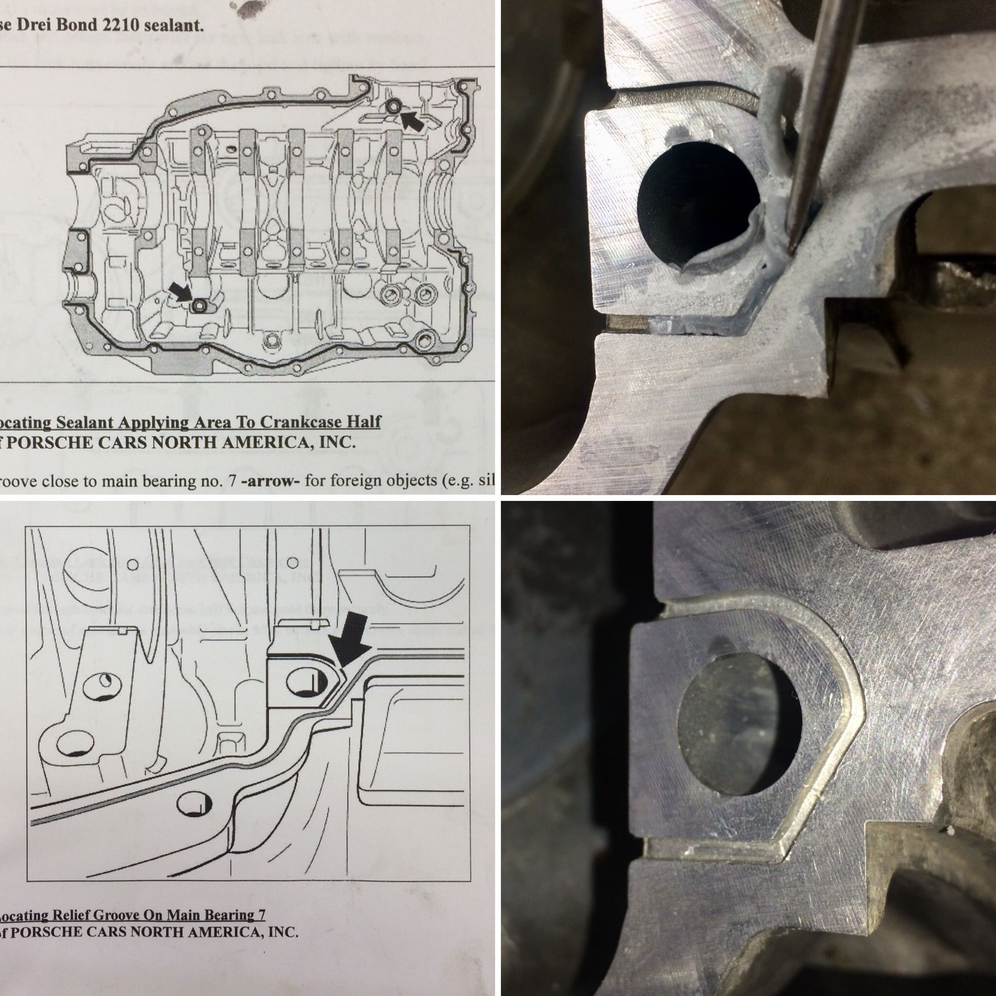
Here's the serendipitous moment that made the redo completely worth the time and effort. Don't block the freaking bypass galley with excessive sealant!!!
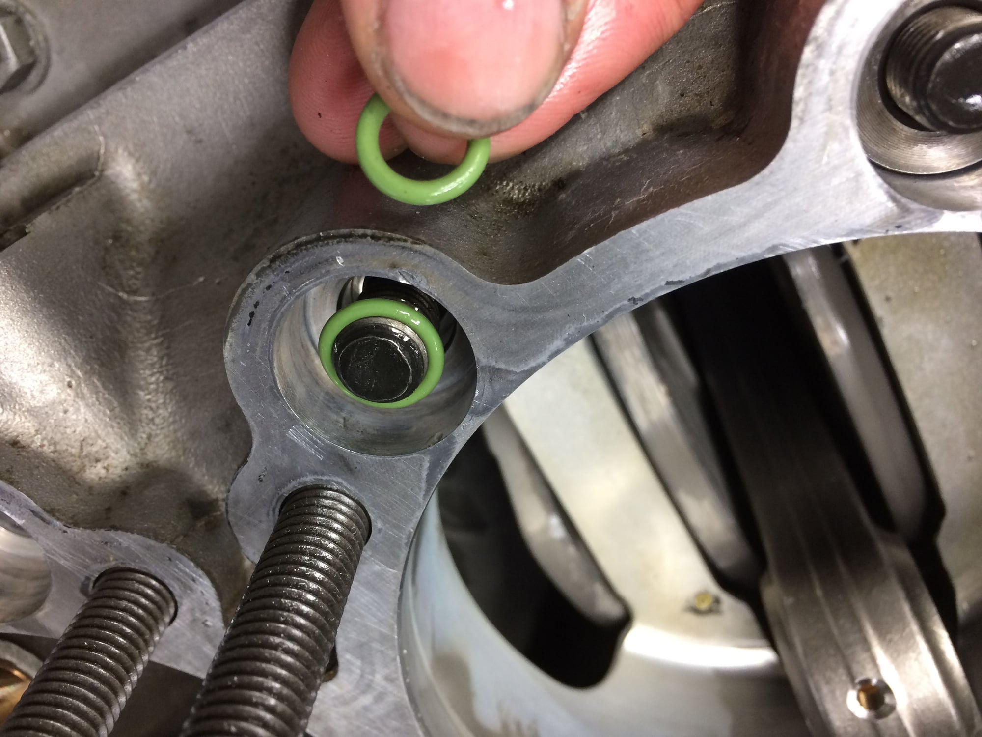
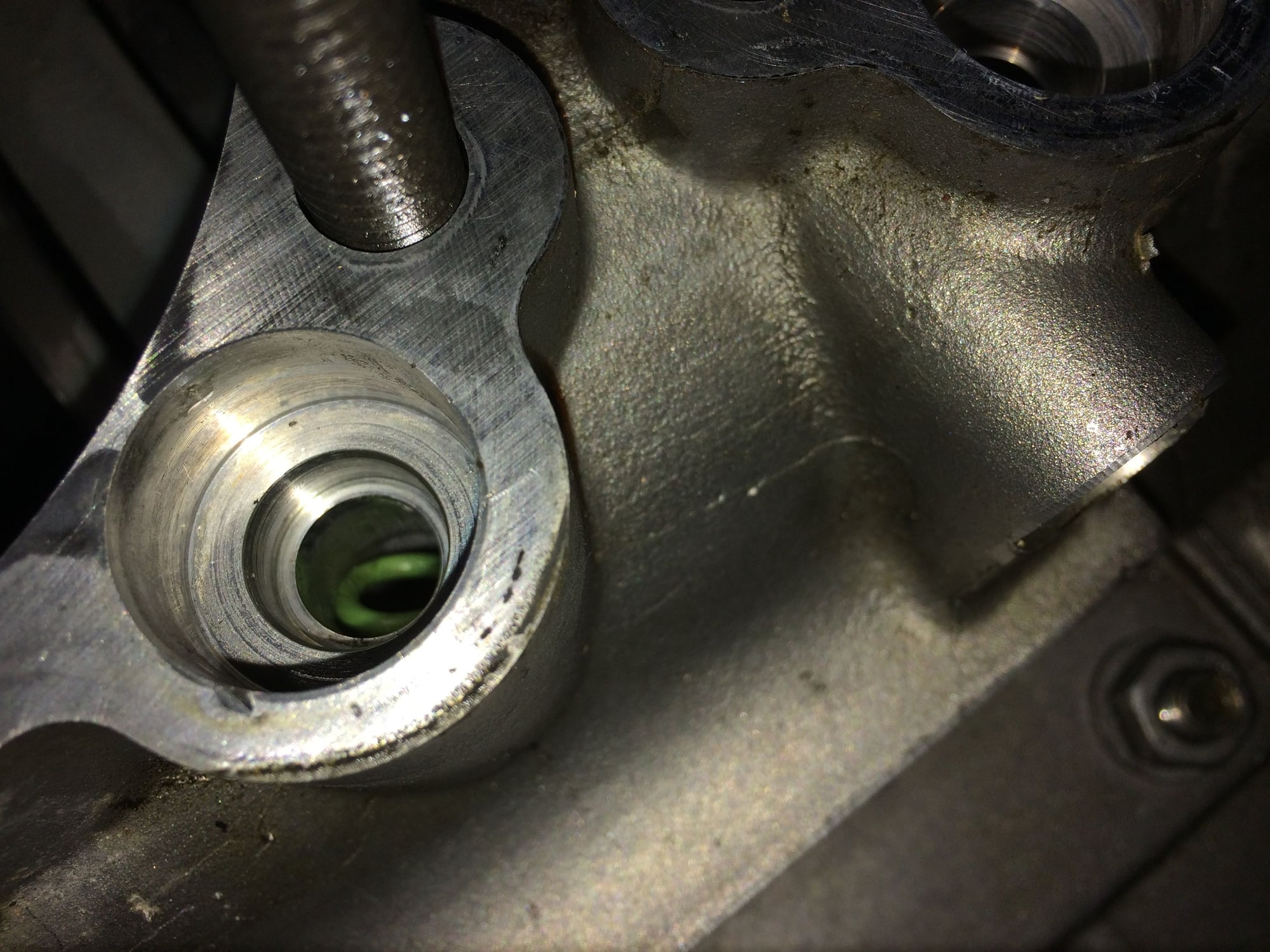
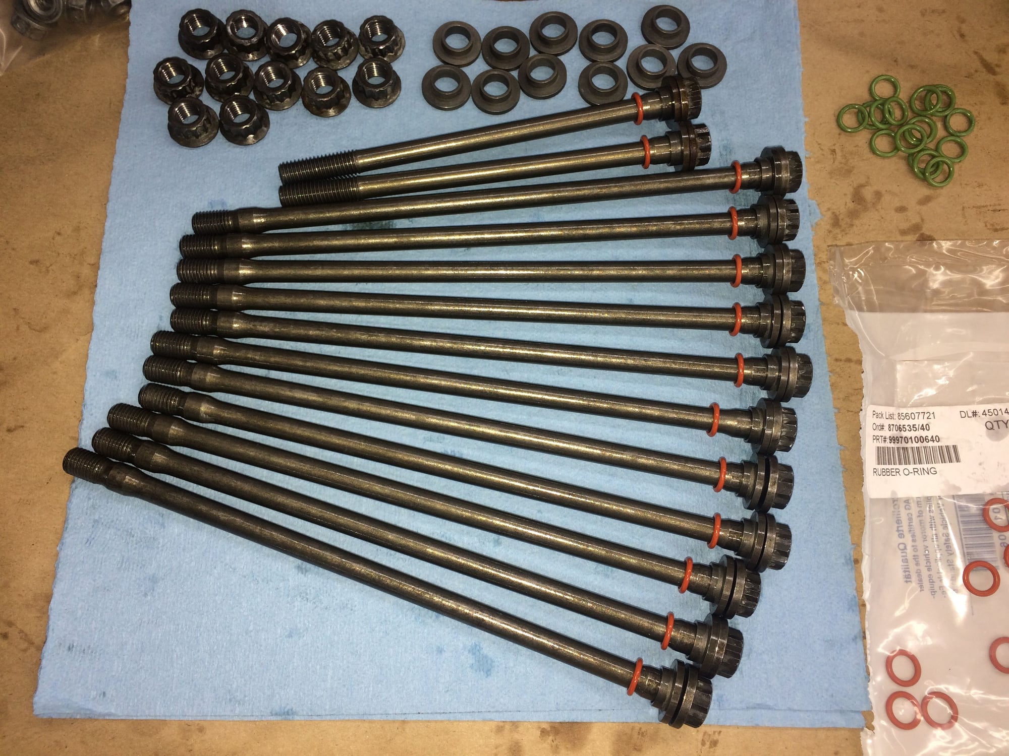
Cleaned and prepped the engine case bolts again with fresh o-rings. The red ones are factory, green ones are aftermarket. No difference whatsoever in function. The first time I didn't have a total of 24 red ones so I used green. Second time I had enough reds.
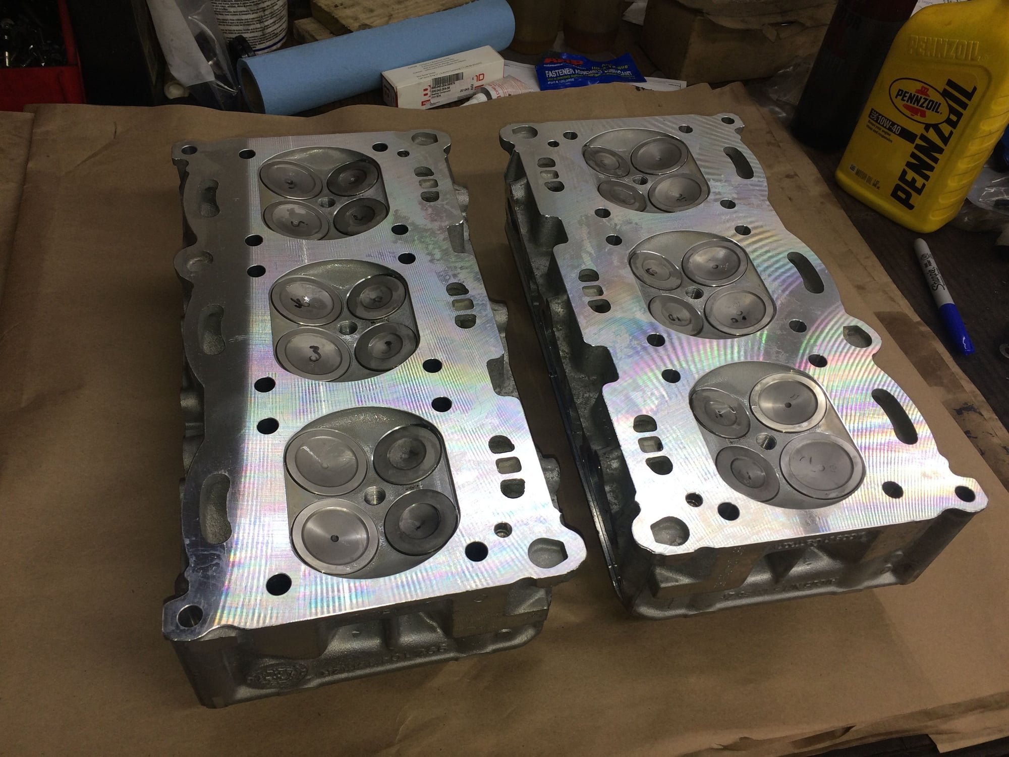
Cylinder heads are rebuilt with Manganese Bronze Alloy valve guides from EBS Racing. My cylinder head guy machined down the intake guides to help increase air flow, head surface milled 0.003" for trueness, all valves checked for straightness and re-faces, 3-angle valve job with seat cut 0.009" depth, valve stem tip machines receptive to seat depth, and of course new valve stem seals.
I really enjoyed the time lapse video - It would be great if you did another for piston/head install.
Glad you enjoyed it. I can't take credit for it though, it wasn't me. I thought about doing a time lapse but not going work since I'm not straight up assembling, I'm taking measurements and making adjustments.
Originally Posted by jasonturbo
Two best threads on RL = This one and Spyrex's 964 build.
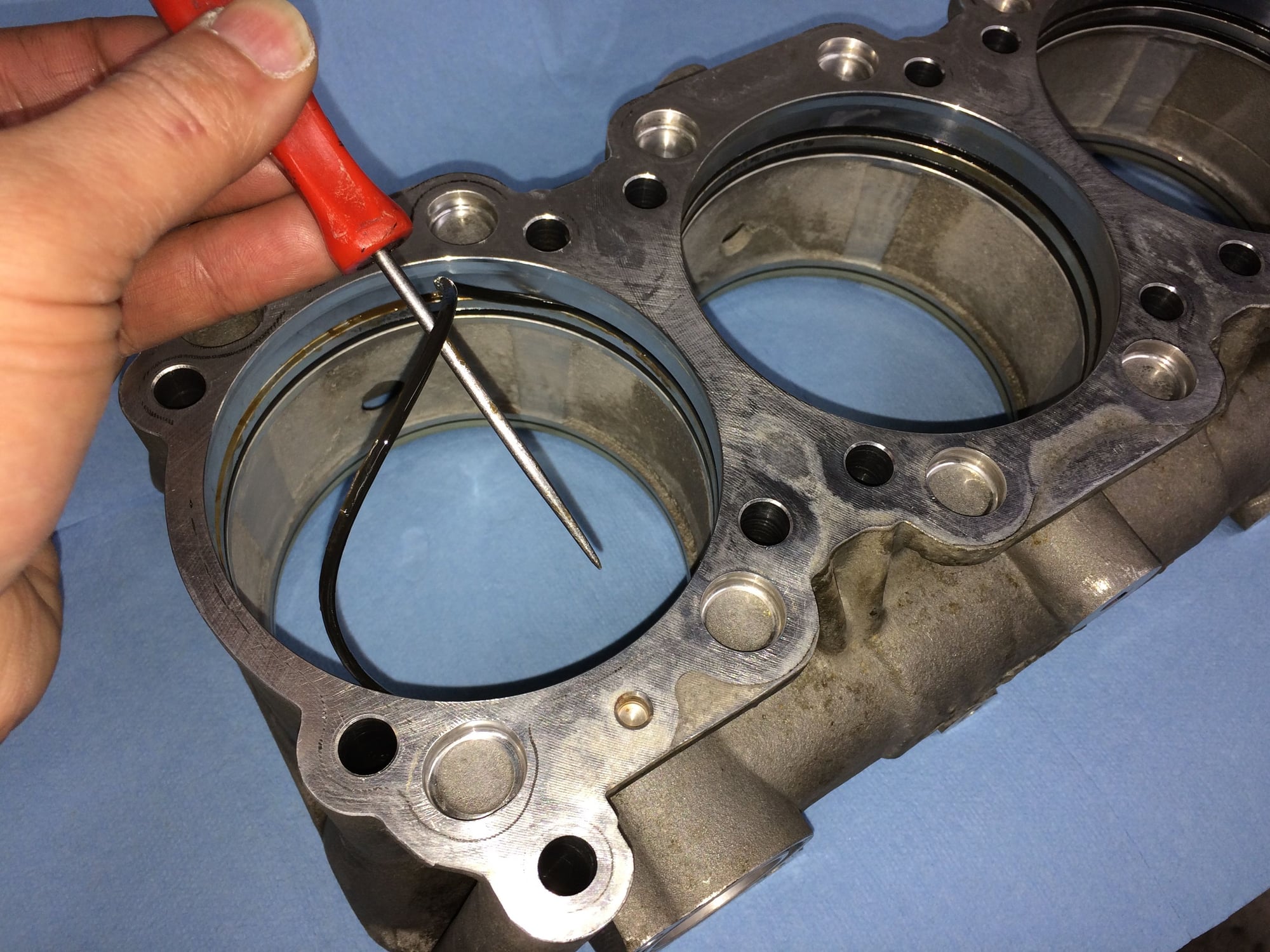
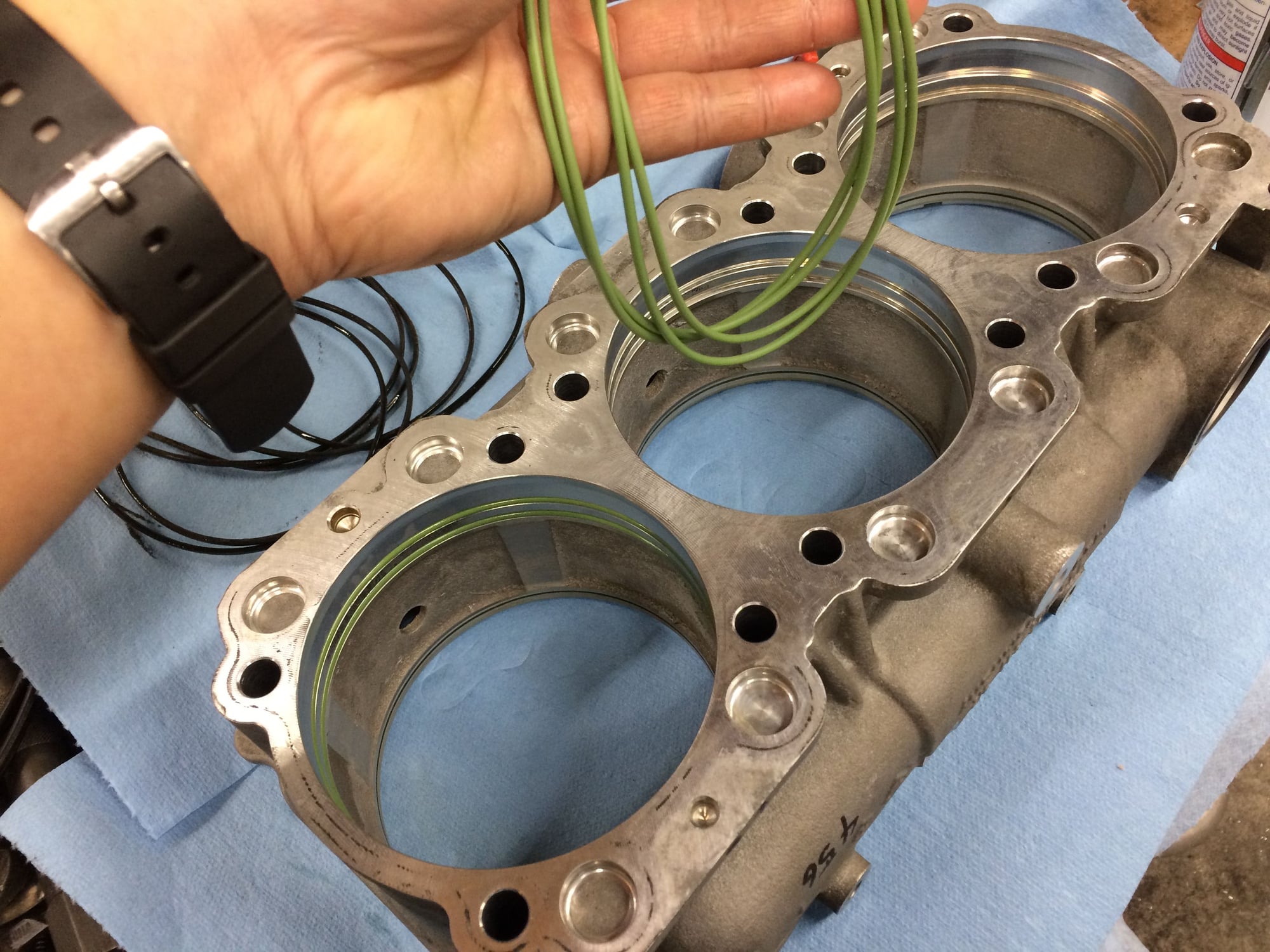
Have photos and videos. Photos first. Each cylinder has three o-rings, two on the cylinder housing one on the cylinder sleeve.
The residual goop behind the o-rings are gross!
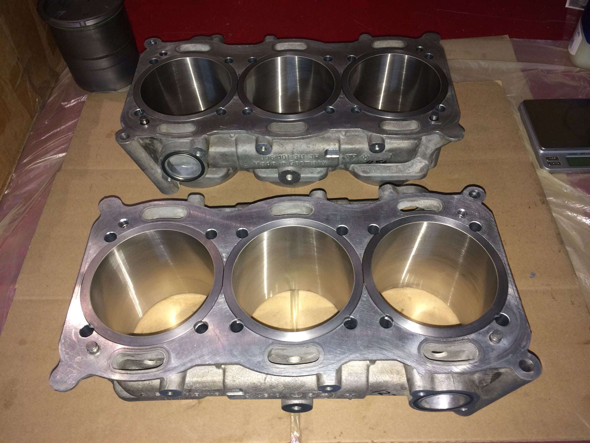
Ready for new o-rings and sleeves. Its amazing that the same housing can hold 600+hp in GT2RS. And its so busy at the shop I'm running out of bench space!
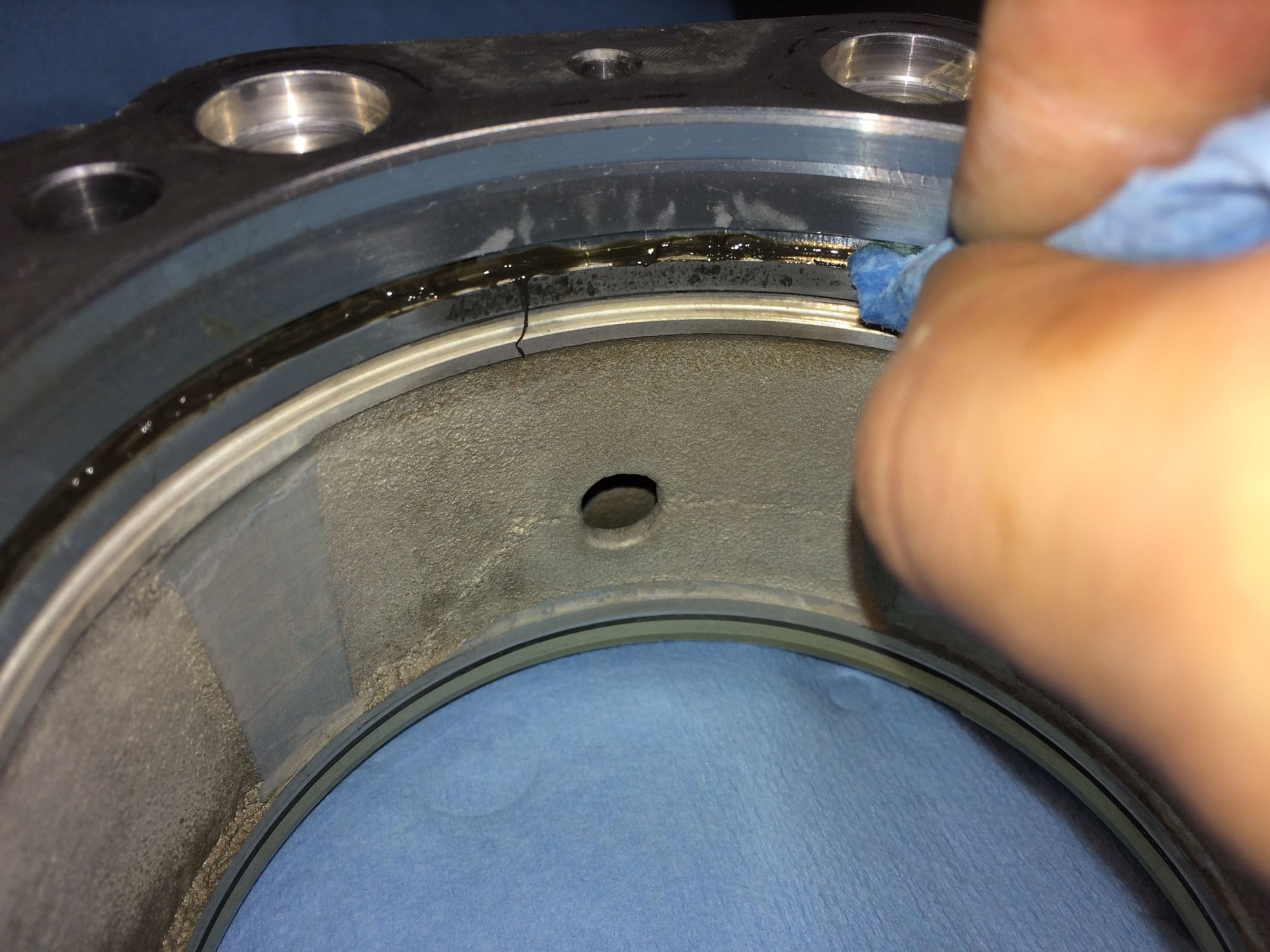
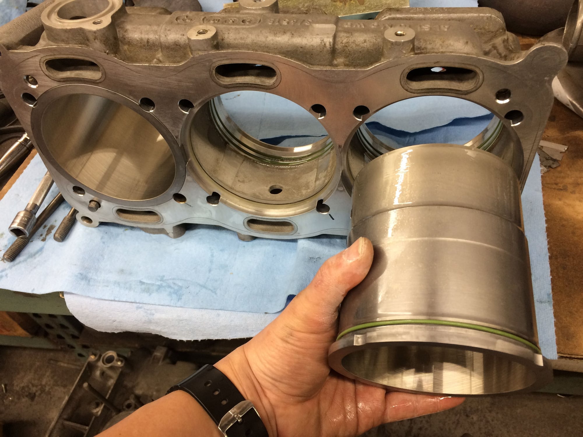
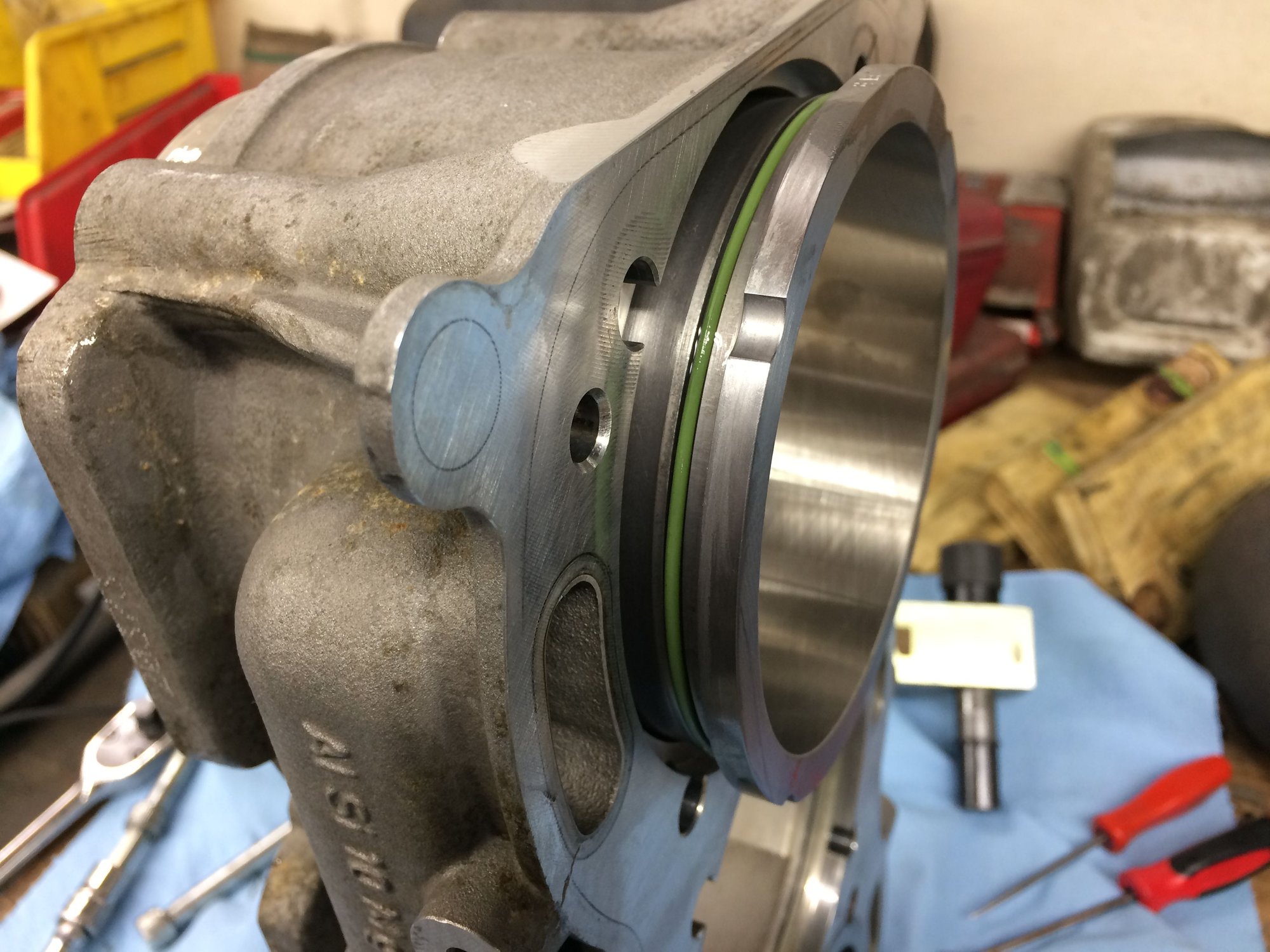
Installing and lubing new o-rings. These o-rings are kind important, they separated coolant for oil.
Carefully inserting the sleeve without unseating the o-rings.
Here's the third o-ring.
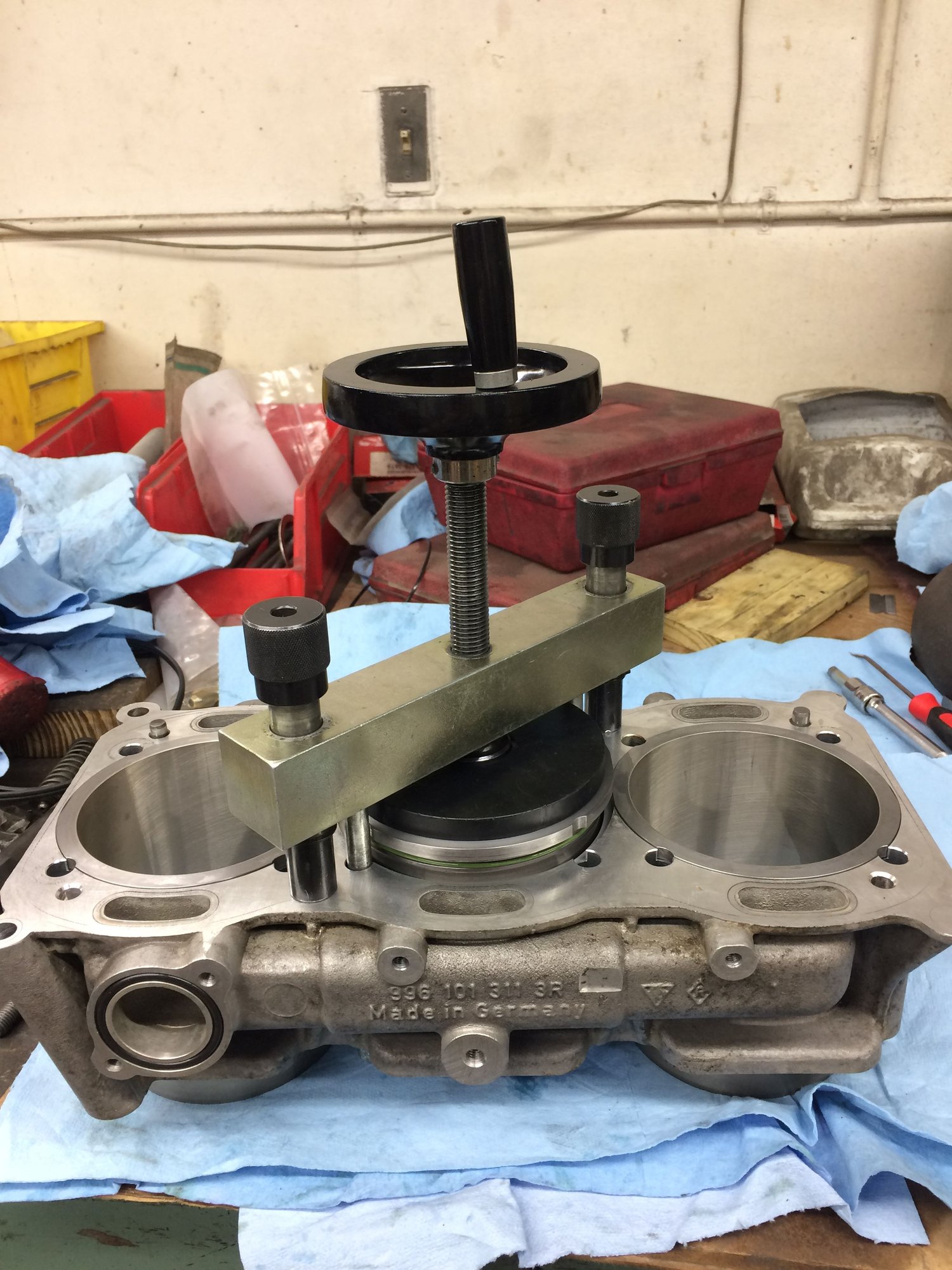
Pressing the sleeves with factory tool.
12:30am. Good night you beautiful sleeves.
Here's the youtube videos. I tried merging the videos with an app but no luck and loss patience with the app so just have individual videos.
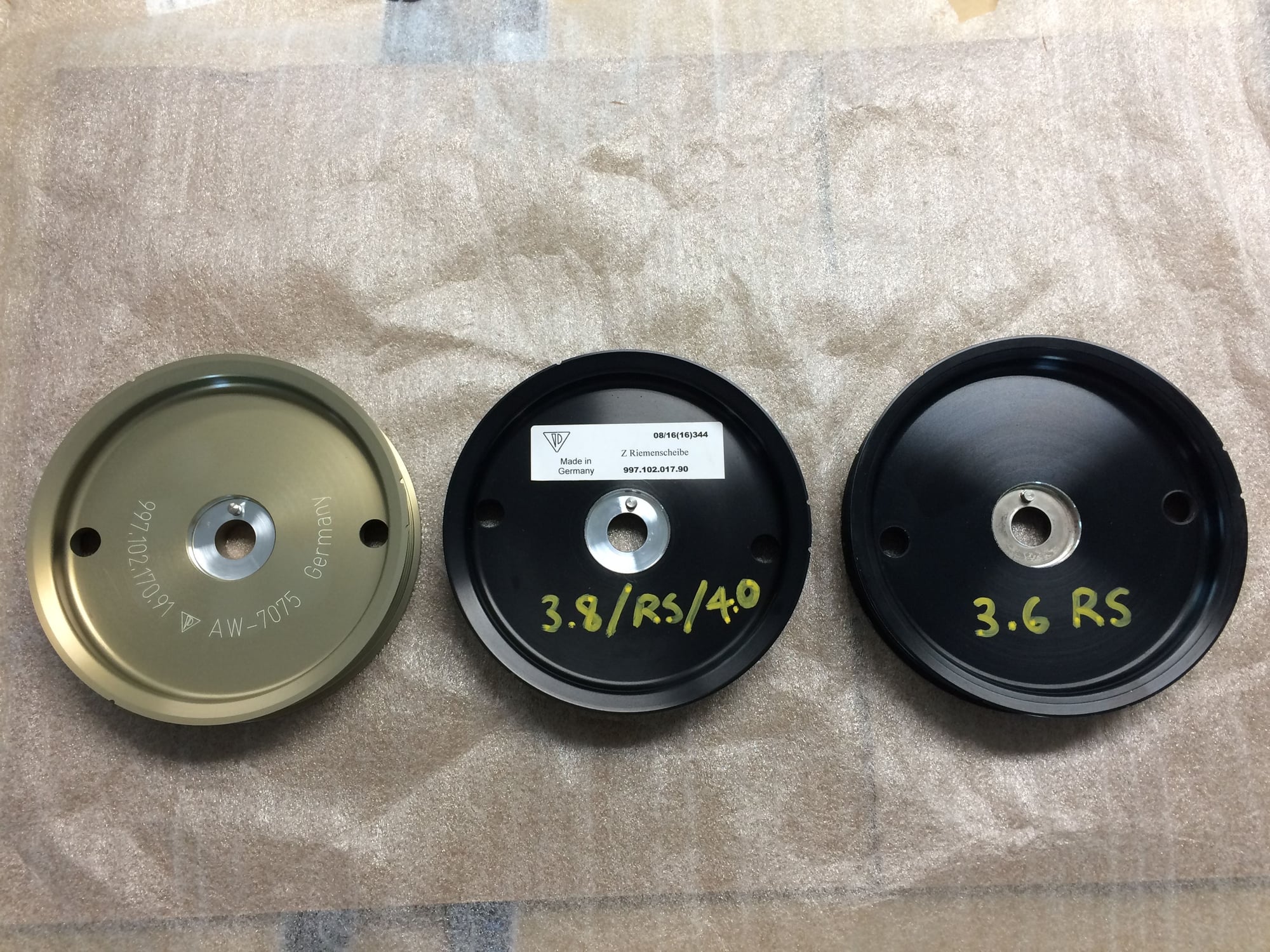
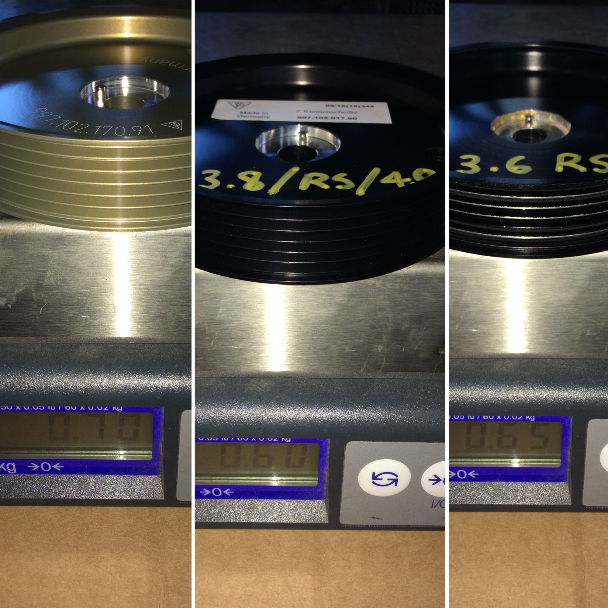
I am not done assembling the long block yet but I wanted to jump ahead on deciding which crank pulley to use. My choices are the following(shown in image below from right to left): 1) 997.1 3.6 RS street car pulley, this is the pulley I installed 3 years ago to match the 3.6 RS LWFW. Had zero issue, has been a solid performer. 2) 997.2 3.8/RS/4.0 street car pulley, my measurement indicates this pulley is a 3% overdrive, running the water pump, alternator, AC compressor at 3% higher rpm than 3.6 pulley, will need approx. 10mm shorter belt than 3.6. 3) 997.2 Cup/991.1 Cup/GT America 4.0 race car pulley, its the gold color pulley, same as above 3% overdrive and needs shorter belt.
Weight difference below in pound(shown below from right to left)- 1) 997.1 3.6 RS street car pulley at 0.65 lb 2) 997.2 3.8/RS/4.0 street car pulley at 0.60 lb 3) 997.2 Cup/991.1 Cup/GT America 4.0 race car pulley at 0.70 lb
The difference between the latter two choice is that the Cup version(gold color pulley) has thicker material in the center area, thus requires a longer bolt. I think I am going to go with the Cup pulley on my silly logic that its the heaviest of the three pulley(by a very small margin) to be the slightest bit closer to the weight of the flywheel at the opposite end of the crankshaft even though the flywheel is greater than 10x the weight of any of the pulleys. Leading a question that has been on my mind, my guess is on any crankshaft there must be a balance factor built in to the crankshaft itself in order to accommodate for the pulley at one end that weights less than one pound and a flywheel on the opposite end that weight 10 to 20 times more, or the weight spinning at each end doesn't matter as long as each spinning object at each end is individually balanced? I am not an engine balancing expert so if there's any balancing experts out there my inquiring mind would like to know.


 02-11-2018, 09:23 AM