
Replacing the clutch in a 997.1 -- Here's how I did it.
 07-10-2014, 12:08 AM
#1
Instructor
Thread Starter
I've got a 2005 997 that I purchased almost 2 years ago. I bought her with 65K miles, and as it sits currently, she's got 75K miles on it. Based on the VIN and build date, she was an early one with the IMS accessible externally. I had the car at an independent shop in Santa Fe last year to read out an error and the mechanic mentioned that my clutch was one of the stiffest he had seen. He said as the clutch wears, they get stiff...so I should think about replacing it. Given that the IMS had not been replaced, I figured it was high time to fix the clutch, replace the IMS with an LN engineering bearing and replace the RMS while I was in there. I did all that work while replacing my clutch, although I didn't bother to document the IMS and RMS work--the Bentley videos online are quite comprehensive. Plus, for most people on this board, the IMS replacement will significantly deviate from what I did.
I'm not calling this a DIY because I'm not sure replacing a clutch is a DIY job for everyone. It was significantly more involved than any of my other work on the 997 (including replacing the water pump myself) and I can honestly say there were times during this process that I wasn't sure saving several thousand dollars in labor costs was worth it. The replacement took me two full weekends and several hours on the weekdays. I did replace the RMS and IMS, which added a day to it, probably, but still it took me much longer than anticipated. Much of that was because I couldn't find a good writeup on the 997 and was trying to work off of 996 writeups. The two are similar, but there are enough differences that I was slowed significantly by trying to research the differences and not screw up.
So, this is first an foremost my attempt to give back to the 997 community. There are many great writeups that I've used on this site and others. I appreciate the work that previous enthusiasts have put into documenting their work. I hope that this is helpful to those who come after me and wonder what goes into doing a clutch replacement. While I do document the way I did it and the sizes of sockets I used and torque values I found, they are merely there for documenting what I used. Do not assume them to be accurate. I have found that Porsche will often change bolt sizes and types (e.g. move from allen to torx) and can/will change torque values (e.g., the recent increase of lug nut bolt torques). So, certainly use some logic if you attempt this yourself--and do not assume the torque values I listed are accurate. The ones I used were found from the what I thought were accurate sources I could find at the time (generally the WMS)...so I didn't just makes torque values up. Still, double check just to verify no typos or things haven't changed.
As to a rough cost to do the clutch replacement, I think it was somewhere between $700 and $900. I bought the clutch kit (which is a clutch, a new pressure plate and a throwout bearing) from Suncoast for between $700-800. Plus I bought a transmission jack from HF for maybe $75 (and I can't imagine attempting this job without a transmission jack...well worth the money to have one on hand). If nothing else is done and you don't need to buy any tools, then that's the cost. Since I ended up doing significantly more than a clutch, the total costs get fuzzy. I found my slave cylinder was bad, adding $150 to it. That required a purge of the hydraulic system and incurred the cost of new fluid (maybe $30...I don't remember) plus a purger tool at $50 or so. I also decided to change the transmission fluid, with a gallon of new fluid coming in at maybe $50-75 as well. Heck I don't remember now. I replaced the RMS, which was about $20 for the RMS. But I bought some 3" PVC connectors and such at the hardware store in order to get the RMS into place...incurring another $30 or so. Then there was the IMS at about $600 plus $200 in tools to get the old one out and the new on in. I also needed some tri-square sockets for one of the transmission bolts. I bought a whole set off of Amazon for $30. Then there was an assortment of 1/2" extensions and wobble extensions that I bought and didn't keep up with the costs. I'd guess at $2000 for the total costs including the costs of a few new tools. That said, I had a garage full of tools to start off with. So I'm not included the costs of sockets, wrenches, jacks, jack stands, etc in that.
The work I show in the following post took place in my garage. I put the car up on jackstands and ultimately had to jack the car up to 25" off the garage floor. That doesn't sound terribly high, but when I did it, I couldn't believe how high I had to get the car. I could have sworn the car was 4'-5' off the ground until I measured it with a tape measure. The height was necessary to get the transmission+deflated transmission jack out from under the car. I think if only the clutch is being replaced, then removing the transmission from under the car may not be necessary and a few inches can be shaved off. Also, working around those jackstands plus the transmission jack and jack to support the motor was annoying. I did manage to do everything on jack stands, but I will admit to cursing at them blocking my access quite frequently.
Last edited by Rotmilky; 07-10-2014 at 11:53 AM.

The following users liked this post:
edwin108 (04-22-2023)
07-10-2014, 12:26 AM
#2
Instructor
Thread Starter
* I first disconnected the battery.
* Next, using a 19 millimeter socket, I loosened the bolts on rear wheels.
* I placed the car up on jacks.
* Using the 19 millimeter socket again, I removed the rear wheels.
* Using a torx t-25 I removed the 4 screws for the rear most under belly shield (the one closest to the motor). The yellow arrows show the approximate locations for those for screws.

* I then removed the next underbelly shield up from the motor. There are 4 torx screws and four 10 millimeter plastic nuts. Red shows nut locations, yellow are torx. I *think* that might be all that needs to be removed, but since I wanted to check all the lines, I took the entire set off the bottom. So it's possible the next set needs to be removed as well.

I then removed the aluminum support cross bar buy removing the two 15 mm bolts.

The location under the car was hard to photograph since I was so close to the transmission. It was roughly between the motor and transmission, if memory serves correctly. Here it is removed from the car:

* Next, using a 19 millimeter socket, I loosened the bolts on rear wheels.
* I placed the car up on jacks.
* Using the 19 millimeter socket again, I removed the rear wheels.
* Using a torx t-25 I removed the 4 screws for the rear most under belly shield (the one closest to the motor). The yellow arrows show the approximate locations for those for screws.
* I then removed the next underbelly shield up from the motor. There are 4 torx screws and four 10 millimeter plastic nuts. Red shows nut locations, yellow are torx. I *think* that might be all that needs to be removed, but since I wanted to check all the lines, I took the entire set off the bottom. So it's possible the next set needs to be removed as well.
I then removed the aluminum support cross bar buy removing the two 15 mm bolts.
The location under the car was hard to photograph since I was so close to the transmission. It was roughly between the motor and transmission, if memory serves correctly. Here it is removed from the car:
07-10-2014, 12:36 AM
#3
Instructor
Thread Starter
After removing the plastic underbelly protection, I then proceeded to disconnect various components from the transmission:
* I removed the 6 allen bolts from the driveshaft on both sides of the transmission. I used 8mm allen. Only 4 are seen here in this crappy dark photo. Sometimes documenting work under a car is sucky and dark. I don't expect to see these in Life magazine anytime soon. In fact, I've never seen photos of clutch replacement in Life, so maybe these represent some of the better?

*I popped open the black electrical box (passenger side) with a flat screwdriver. I removed the 13 millimeter bolt holding the B+ connector. The photo below shows the 13mm bolt with the box open. The photo a couple below that shows the box closed to make it easier to recognize.
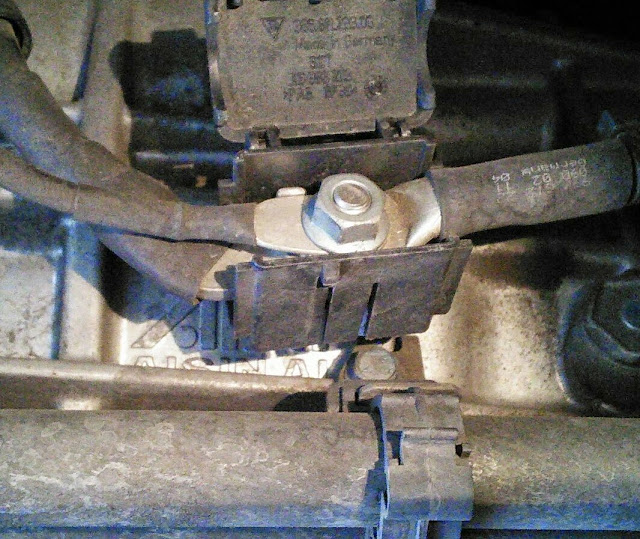
* I then disconnect the B+ lead from the transmission cross support. To do this, I inserted a flat tipped screw driver into the bottom snap portion of the plastic holder and twisted. This opened up the clamp and I then could pull the B+ wire out and feed it through the support. The screwdriver I'm using to pop open the cable support is shown coming in from the center top.

*I removed the cabling attached to the passenger side of the transmission. This is called the B+ wire. There were four bolt (10 mm) holding it along the passenger side of my transmission. Two are shown here near the front of the transmission (front referring to the front of the car).

The third is found above the drive shaft flange and the last is near the rear of the transmission:

* I removed the 6 allen bolts from the driveshaft on both sides of the transmission. I used 8mm allen. Only 4 are seen here in this crappy dark photo. Sometimes documenting work under a car is sucky and dark. I don't expect to see these in Life magazine anytime soon. In fact, I've never seen photos of clutch replacement in Life, so maybe these represent some of the better?
*I popped open the black electrical box (passenger side) with a flat screwdriver. I removed the 13 millimeter bolt holding the B+ connector. The photo below shows the 13mm bolt with the box open. The photo a couple below that shows the box closed to make it easier to recognize.
* I then disconnect the B+ lead from the transmission cross support. To do this, I inserted a flat tipped screw driver into the bottom snap portion of the plastic holder and twisted. This opened up the clamp and I then could pull the B+ wire out and feed it through the support. The screwdriver I'm using to pop open the cable support is shown coming in from the center top.
*I removed the cabling attached to the passenger side of the transmission. This is called the B+ wire. There were four bolt (10 mm) holding it along the passenger side of my transmission. Two are shown here near the front of the transmission (front referring to the front of the car).
The third is found above the drive shaft flange and the last is near the rear of the transmission:
Last edited by Rotmilky; 07-10-2014 at 01:50 AM.
07-10-2014, 01:46 AM
#4
Instructor
Thread Starter
Once I was done removing stuff associated with the B+ connector, I next moved to the coolant lines
* I removed the connectors that hold the cooler lines on. One is just below the B+ cable on the passenger side, the other is just below the drive shaft flange. Here is the one below the B+ cable connection:

And here is the bolt just below the drive shaft flange:

* I then removed the 2 shift linkage connectors. I simply inserted a screwdriver and popped them off. Then the cables were removed from the support on the transmission by squeezing the two tabs together and pulling the cable down and off the support. Those are shown by the arrows.

* Next I removed two 13 millimeter bolts from the slave cylinder and slid the slave cylinder out of the transmission. I couldn't see these and had to feel for them. Here is what those bolts look like if you could see them:

The slave cylinder ultimately was bad, of course. So the work I went through to not bleed the hydraulic system was wasted. Murphy at his finest. I disconnected the hydraulic line to the slave cylinder. I *think* it was two 15mm wrenches necessary to remove them but I wasn't going to remove it until I realized the slave was bad and needed to come off. One of the nuts needed to remove the hydraulic line for the slave is shown in a couple of photos above (the one showing the linkages connected to the trans) with the red arrow. I ended up catching a couple of cups of brake fluid in a container when I disconnected the slave cylinder.
The slave cylinder with ruptured boot is shown below.

Most of the prior posts I read did not disconnect the hydraulic line...but putting the slave back onto the transmission while not being able to see and working against the spring force of the clutch seemed to not be easy. I don't know which is a bigger pain--disconnecting the hydraulic line and bleeding the system later or leaving the line in place and struggling to shove the slave back into place while not being able to see.
* I removed the connectors that hold the cooler lines on. One is just below the B+ cable on the passenger side, the other is just below the drive shaft flange. Here is the one below the B+ cable connection:
And here is the bolt just below the drive shaft flange:
* I then removed the 2 shift linkage connectors. I simply inserted a screwdriver and popped them off. Then the cables were removed from the support on the transmission by squeezing the two tabs together and pulling the cable down and off the support. Those are shown by the arrows.
* Next I removed two 13 millimeter bolts from the slave cylinder and slid the slave cylinder out of the transmission. I couldn't see these and had to feel for them. Here is what those bolts look like if you could see them:
The slave cylinder ultimately was bad, of course. So the work I went through to not bleed the hydraulic system was wasted. Murphy at his finest. I disconnected the hydraulic line to the slave cylinder. I *think* it was two 15mm wrenches necessary to remove them but I wasn't going to remove it until I realized the slave was bad and needed to come off. One of the nuts needed to remove the hydraulic line for the slave is shown in a couple of photos above (the one showing the linkages connected to the trans) with the red arrow. I ended up catching a couple of cups of brake fluid in a container when I disconnected the slave cylinder.
The slave cylinder with ruptured boot is shown below.
Most of the prior posts I read did not disconnect the hydraulic line...but putting the slave back onto the transmission while not being able to see and working against the spring force of the clutch seemed to not be easy. I don't know which is a bigger pain--disconnecting the hydraulic line and bleeding the system later or leaving the line in place and struggling to shove the slave back into place while not being able to see.
Last edited by Rotmilky; 07-10-2014 at 08:48 AM.

 07-10-2014, 09:03 AM
#6
Instructor
Thread Starter
I placed a jack under motor to support it. I slid the transmission jack into place and strapped transmission to jack.

The height of the car and the size of the transmission caused some headaches. In order to get the car high enough to get the transmission out, I had to shim the motor jack and found out that my transmission jack wasn't quite tall enough to reach the transmission either. So, I had to lower the car enough that my transmission jack didn't bottom out. Then when I went to pull the transmission out, I had to raise everything again. This is part of the reason it took me so long to finish this project.
Once the transmission jack was strapped in place, I started removing bolts holding it to the car. I removed four nuts from the transmission support plate, and two nuts from the cross support strap. The support plate nuts are circled and the bolts connecting everything to the trans has arrows pointing to their general location. I think they were all 16mm nuts. The four from the bottom of the plate needed a deep socket in order to seat. It was really hard to get a decent photo of that area. The camera was too close to the bottom of the car. The end of the transmission can be seen in the upper right center of the view. So, these pieces mount at the end of the trans and beyond.

Here is a photo of one of the collar support bolts (circled) and one of the through bolts that mount the transmission to the support collar (arrow).

Here are the two pieces of the transmission support after being removed and cleaned up. The circles show the bolts that hold the rear of the trans to the underside of the car. The arrows point to the through bolts that hold these support pieces to the rear of the transmission. In the photo, the front of the car is toward the top of the photo.

Once all of these bolts are removed, the transmission jack can be lowered. This lowers the back of the transmission enough to be able to pull the collar off and past the transmission. It was tight. I had to do a little rotating and then I had to squeeze the arms past some soft coolant hoses. I was careful while going across those hoses--I didn't want to rip them.
A couple of notes about the transmission crossmember support. The smooth surface of the crossmember points towards the rear of the car. The b+ wire threads through the triangular gap on the passenger side. Also the shift cable and the select cable lie above above the crossmember on the driver side. I made a mental note so that I'd remember to reinstall everything correctly in relation to that crossmember.
Lastly, I removed the reverse light plug. The plug is found a few inches above in front of the passenger side axle connection point. I think on the 996, this plug is found near the support collar and harness. It took me half an hour to find the stupid thing because I was looking at photos of the 996.
The height of the car and the size of the transmission caused some headaches. In order to get the car high enough to get the transmission out, I had to shim the motor jack and found out that my transmission jack wasn't quite tall enough to reach the transmission either. So, I had to lower the car enough that my transmission jack didn't bottom out. Then when I went to pull the transmission out, I had to raise everything again. This is part of the reason it took me so long to finish this project.
Once the transmission jack was strapped in place, I started removing bolts holding it to the car. I removed four nuts from the transmission support plate, and two nuts from the cross support strap. The support plate nuts are circled and the bolts connecting everything to the trans has arrows pointing to their general location. I think they were all 16mm nuts. The four from the bottom of the plate needed a deep socket in order to seat. It was really hard to get a decent photo of that area. The camera was too close to the bottom of the car. The end of the transmission can be seen in the upper right center of the view. So, these pieces mount at the end of the trans and beyond.
Here is a photo of one of the collar support bolts (circled) and one of the through bolts that mount the transmission to the support collar (arrow).
Here are the two pieces of the transmission support after being removed and cleaned up. The circles show the bolts that hold the rear of the trans to the underside of the car. The arrows point to the through bolts that hold these support pieces to the rear of the transmission. In the photo, the front of the car is toward the top of the photo.
Once all of these bolts are removed, the transmission jack can be lowered. This lowers the back of the transmission enough to be able to pull the collar off and past the transmission. It was tight. I had to do a little rotating and then I had to squeeze the arms past some soft coolant hoses. I was careful while going across those hoses--I didn't want to rip them.
A couple of notes about the transmission crossmember support. The smooth surface of the crossmember points towards the rear of the car. The b+ wire threads through the triangular gap on the passenger side. Also the shift cable and the select cable lie above above the crossmember on the driver side. I made a mental note so that I'd remember to reinstall everything correctly in relation to that crossmember.
Lastly, I removed the reverse light plug. The plug is found a few inches above in front of the passenger side axle connection point. I think on the 996, this plug is found near the support collar and harness. It took me half an hour to find the stupid thing because I was looking at photos of the 996.
The following users liked this post:
Signore116 (10-25-2020)
07-10-2014, 09:26 AM
#7
Instructor
Thread Starter
Now everything was off the transmission except the bolts holding it to the motor. Just pop off those bolts and I was basically done. Ug, this took me a day at least, maybe a day and a half the first time. A lot of that time was scratching my head trying to figure out how to get to the top bolt and then dashing off to the hardware store for yet another extension or wobble extensions or u-joint extension or crowfoot. Space is tight and sight lines are limited. Often, the sight line is also your space, so once I stuck my arm up there, I couldn't see and had to feel around. I ultimately got it done and if I had to do over, could probably do it in an hour, mainly because I have all the extensions and wobble accessories I need. But I think I could get by with about 25-30" of extensions, a wobble extension and a ratchet with a breakover handle of I had to.
Anyway, I did manage to remove the 8 bolts holding the transmission to the motor. I marked the bolts as they came out in the order that they were removed because their sizes are different. Bolts #1 through #3 are 16 millimeter. Bolt 4 is a 10 millimeter tri-square bolt. I got mine off of Amazon, but the local auto parts store had them as well. Bolt #5 is a 15 millimeter bolt with a 15 millimeter nut on the back side. Bolts #6 through #8 are 16 millimeter bolts. The most difficult bolts to remove are #1 and #2 due to restricted access. For me, the easiest way to access them was to put a wobble extension on the 16mm socket. Then assemble additional extensions up to ~25". That moved my ratchet off the front end of the transmission and into some of the tunnel space and gave me enough room to get a decent amount of rotation on the ratchet. Here's a photo of the first four bolts labeled by number. The worst one of the bunch (#1) is right on top.

And here are the driver side bolts. These generally are much easier to remove. Access is better on this side.

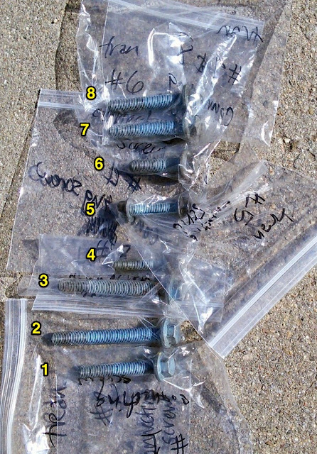
Here are the bolts corresponding to holes 1 through 8. Notice that there are a number of different sizes to them. I put them all in separate plastic baggies to keep up with them. Bolt #4 is the tri-square. A triple square socket (also called XZN socket) is needed to remove it. Autozone had one, but I opted just to get a 10 piece set off of Amazon for $25. Note that Bolt #5 has a nut on the back of it. One of the bolts, maybe it was #3 seemed to have corrosion on it from water splashing onto it. I didn't have any trouble removing it, but I read reports on some 996 transmissions that this bolt was corroded enough that the transmission flange broke off around the bolt while removing the bolt. Hopefully that's not a problem for the 997.
Anyway, I did manage to remove the 8 bolts holding the transmission to the motor. I marked the bolts as they came out in the order that they were removed because their sizes are different. Bolts #1 through #3 are 16 millimeter. Bolt 4 is a 10 millimeter tri-square bolt. I got mine off of Amazon, but the local auto parts store had them as well. Bolt #5 is a 15 millimeter bolt with a 15 millimeter nut on the back side. Bolts #6 through #8 are 16 millimeter bolts. The most difficult bolts to remove are #1 and #2 due to restricted access. For me, the easiest way to access them was to put a wobble extension on the 16mm socket. Then assemble additional extensions up to ~25". That moved my ratchet off the front end of the transmission and into some of the tunnel space and gave me enough room to get a decent amount of rotation on the ratchet. Here's a photo of the first four bolts labeled by number. The worst one of the bunch (#1) is right on top.
And here are the driver side bolts. These generally are much easier to remove. Access is better on this side.
Here are the bolts corresponding to holes 1 through 8. Notice that there are a number of different sizes to them. I put them all in separate plastic baggies to keep up with them. Bolt #4 is the tri-square. A triple square socket (also called XZN socket) is needed to remove it. Autozone had one, but I opted just to get a 10 piece set off of Amazon for $25. Note that Bolt #5 has a nut on the back of it. One of the bolts, maybe it was #3 seemed to have corrosion on it from water splashing onto it. I didn't have any trouble removing it, but I read reports on some 996 transmissions that this bolt was corroded enough that the transmission flange broke off around the bolt while removing the bolt. Hopefully that's not a problem for the 997.
Trending Topics
07-10-2014, 10:00 AM
#8
Instructor
Thread Starter
Now that the bolts were out of the transmission, I lowered the transmission jack a little bit and rocked the transmission back and forth. I raised the transmission jack a little bit and slowly rocked the transmission back and forth. Doing this, the transmission slowly separated from the motor. It took maybe half an hour of shaking back and forth raising, and then lowering in order for the transmission to fully separate. Initially both the transmission and the motor would move together when shaking. As the transmission moved further away from the motor, just the transmission would move when I rocked it back and forth. I was able to ultimately remove the transmission without using any kind of tools to pry it from the motor. It was slow, but I was worried that prying would score the softer aluminum of the transmission housing. Ultimately, I didn't need to pry.
Once the transmission was detached, I slowly lowered the transmission, carefully checking to make sure nothing was hanging. Initially, I had to move the transmission back about 1" to clear a lower support. This is much easier to do if the support collar has been removed. If it's still in place at this point (like it was when I did it), it blocks the transmission from sliding back and makes clearing the support a pain in the neck. Once I managed to slide the transmission back far enough to clear the support, I could lower away with vigor. I'd lower maybe 1/2", then check around to see if anything was hanging on the transmission when it shouldn't be. The electrical connection and coolant cables on the passenger side tended to hang on the axle flange. On the driver side, the gearing selector supports tended to hang up on some soft coolant lines near the front of the tunnel. I was really careful to push the coolant lines in and around the support as I lowered--I didn't want to rip the lines.
The pads at the front of the transmission behind the transmission yolk and cross beam support fell off while shaking the transmission during removal. Here is what they look like. They fell off repeatedly during the install and removal process. I took a photo so I'd remember the direction.

Once the transmission was out of way, I could get on with the clutch replacement. I removed the six torx bolts using t-50 from the pressure plate.

Once those were removed, I could slide the pressure plate and clutch off. There are 3 pins on the flywheel that fit into the pressure plate. I had to do a little bit of light prying on the edge of the pressure plate to get it to come off.
At this point, my work continued as I removed the flywheel in order to do the IMS and RMS change. I used the Bentley videos for that part. Most 997 owners won't have the external serviceable IMS, so that's really not interesting anyway. However, I think there are RMS issues on the 997, here is the additional work I needed to do to replace the RMS. If I weren't doing the RMS (and IMS too), I would have started putting the new clutch on at this point.
Once the transmission was detached, I slowly lowered the transmission, carefully checking to make sure nothing was hanging. Initially, I had to move the transmission back about 1" to clear a lower support. This is much easier to do if the support collar has been removed. If it's still in place at this point (like it was when I did it), it blocks the transmission from sliding back and makes clearing the support a pain in the neck. Once I managed to slide the transmission back far enough to clear the support, I could lower away with vigor. I'd lower maybe 1/2", then check around to see if anything was hanging on the transmission when it shouldn't be. The electrical connection and coolant cables on the passenger side tended to hang on the axle flange. On the driver side, the gearing selector supports tended to hang up on some soft coolant lines near the front of the tunnel. I was really careful to push the coolant lines in and around the support as I lowered--I didn't want to rip the lines.
The pads at the front of the transmission behind the transmission yolk and cross beam support fell off while shaking the transmission during removal. Here is what they look like. They fell off repeatedly during the install and removal process. I took a photo so I'd remember the direction.
Once the transmission was out of way, I could get on with the clutch replacement. I removed the six torx bolts using t-50 from the pressure plate.
Once those were removed, I could slide the pressure plate and clutch off. There are 3 pins on the flywheel that fit into the pressure plate. I had to do a little bit of light prying on the edge of the pressure plate to get it to come off.
At this point, my work continued as I removed the flywheel in order to do the IMS and RMS change. I used the Bentley videos for that part. Most 997 owners won't have the external serviceable IMS, so that's really not interesting anyway. However, I think there are RMS issues on the 997, here is the additional work I needed to do to replace the RMS. If I weren't doing the RMS (and IMS too), I would have started putting the new clutch on at this point.
07-10-2014, 10:06 AM
#9
Instructor
Thread Starter
I removed the eight bolts holding the flywheel on using t-55 torx. The motor wanted to turn when breaking these bolts free. To keep it from rotating, I threaded one of the transmission bolts into place and threaded one of the pressure plate bolts back into place. Then I went to the hardware store and got a ring-shaped clasp large enough to go around both. This held the flywheel enough that I could break the botls free.

Once the bolts were out, I could pull the flywheel. Wow that sucker was heavier than I expected. Once the flywheel was removed, I could get to the RMS (and IMS). Here's a photo of my old one. The seal was good and dry, but I figured I might as well replace it since it was pretty cheap and it would be hopefully 100K+ miles before I'd be back in there (depending on how this clutch holds up). Also my purty new LN engineering bearing is shown at the bottom. This photo was taken as I was starting to button up after installing the new IMS

Removing the old RMS was a bit of a challenge. I ultimately followed the Bentley video. This required drilling a 3mm hole in the seal, inserting a metal screw and washer and then grabbing the head of the screw/washer with a slide hammer, I could knock it out. Once it started to come, it popped right out.
To put the new one in, I found some online posts about using a 3" PVC connector and screwing in the flywheel bolts to pull it on. I couldn't get this to work for me. So I used a rubber mallet to hammer on the edge of the PVC connector. There is no stop on the back side of the seal, so I had to use something to make sure I put it back in the right spot. I used calipers to make sure the seal was going in straight and was deep enough. The original seal I removed was 11mm below the flywheel flange. I found a number of posts suggesting 13mm. I decided to split the difference and put my seal at 12.5 mm below the flywheel flange. Here's the new one in place.

Finally, I reinstalled the flywheel. The bolts that I took out...they're stretch bolts and can't be reused. Luckily, the nice guys at Pelican told me that when I was getting the seal, so I had new ones on hand. Installation of the bolts is a bit weird. They need to be torqued to 20 ft-lbs, and then rotated 120 degrees beyond that. So, I marked each one of them at about 10:30 position and then rotated them to 3 o'clock. That's about 120 degrees. Here's a photo of them torqued and stretched. The faint mark at 3 o'clock can be seen on the bolts. I had to use my fancy clippy thing to keep the flywheel from turning while torquing the bolts.

Once the bolts were out, I could pull the flywheel. Wow that sucker was heavier than I expected. Once the flywheel was removed, I could get to the RMS (and IMS). Here's a photo of my old one. The seal was good and dry, but I figured I might as well replace it since it was pretty cheap and it would be hopefully 100K+ miles before I'd be back in there (depending on how this clutch holds up). Also my purty new LN engineering bearing is shown at the bottom. This photo was taken as I was starting to button up after installing the new IMS
Removing the old RMS was a bit of a challenge. I ultimately followed the Bentley video. This required drilling a 3mm hole in the seal, inserting a metal screw and washer and then grabbing the head of the screw/washer with a slide hammer, I could knock it out. Once it started to come, it popped right out.
To put the new one in, I found some online posts about using a 3" PVC connector and screwing in the flywheel bolts to pull it on. I couldn't get this to work for me. So I used a rubber mallet to hammer on the edge of the PVC connector. There is no stop on the back side of the seal, so I had to use something to make sure I put it back in the right spot. I used calipers to make sure the seal was going in straight and was deep enough. The original seal I removed was 11mm below the flywheel flange. I found a number of posts suggesting 13mm. I decided to split the difference and put my seal at 12.5 mm below the flywheel flange. Here's the new one in place.
Finally, I reinstalled the flywheel. The bolts that I took out...they're stretch bolts and can't be reused. Luckily, the nice guys at Pelican told me that when I was getting the seal, so I had new ones on hand. Installation of the bolts is a bit weird. They need to be torqued to 20 ft-lbs, and then rotated 120 degrees beyond that. So, I marked each one of them at about 10:30 position and then rotated them to 3 o'clock. That's about 120 degrees. Here's a photo of them torqued and stretched. The faint mark at 3 o'clock can be seen on the bolts. I had to use my fancy clippy thing to keep the flywheel from turning while torquing the bolts.
Last edited by Rotmilky; 07-10-2014 at 10:51 AM.
07-10-2014, 11:06 AM
#11
Instructor
Thread Starter
Time to install the new clutch. Put the new clutch on, and slid my new pressure plate over the 3 holding pins on the flywheel. I put the 6 bolts back into the pressure plate with enough tension to keep the clutch from falling to the bottom but not so much that I couldn't slide the clutch around.
I inserted my clutch alignment tool. It's simply a piece of plastic that has spines that slide into the clutch splines and a cylinderical tip that slides into the guide bearing in the flywheel (see the center hole in the flywheel photo above). This should center the clutch with that guide bearing ensuring the transmission with easily slip into place. Here's a photo with my plastic alignment tool aligning the clutch. At this point, I made a rather large error in judgment. I assumed that this plastic tool was of a high quality product manufactured to high tolerances and would thus center my clutch with a great deal of accuracy. Oooh, that was a bad assumption. I should have stuck with my gut instinct of 'plastic = crap'.

Anyway, before I get ahead of myself here with the clutch alignment, I also replaced the throwout bearing. It's found on the arm inside the transmission. I removed the arm by pushing the two ears of the clip through the window and snapping the bottom of the arm out of the clip. The ears of the clip and the bottom part can be seen at the bottom of the throwout arm here. This is actually a photo with the new throwout bearing installed--there was so much clutch dust in the transmission that everything was black before I cleaned it up.
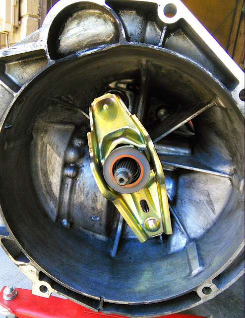
Putting the new throwout bearing on is as simple as squeezing the two clips, pulling the old bearing out and clicking the new one into place

Then I snapped the arm back into place on the transmission.
Ok, now back to clutch alignment and transmission reinstall. I torqued the pressure plate bolts to 17 ft/lbs and then pulled the alignment tool. At this point, it was time to slide the transmission back into place. I worked for many hours trying to get the transmission in. It took awhile just to get the transmission wiggled into the correct position for it to slide the splines into the slots in the clutch. Then the transmission got stuck on the last 1/2". It would not go any farther. I didn't want to use the bolts to pull it into place--the clutch really should be able to be moved into place by hand. Slowly, yea, but it should move. Mine WAS NOT moving and pulling it into place by the bolts would end up breaking something. I think I invented new curse words during this process. Ultimately, It seems my clutch wasn't aligned to the pilot bearing. I looked at my clutch alignment tool (remember--plastic probably made in China) and noted the tip was warped. It's got a small angular tilt to it. Son of a....the tool sucks. So, off with the transmission to check alignment. That was a waste of many hours. I'll never trust one of those plastic alignment tools again. I'll at least always visually check the alignment--which is how I ended up aligning the clutch anyway.
Instead of using the alignment tool, I aligned the clutch by eyeball. I inserted a wooden dowel shimmed with tape around one end into the guide bearing in the flywheel. Then I centered the clutch with that dowel. This time through, I check and re-checked the clutch just to make sure I was darned certain it was centered. I adjusted it probably half a dozen times before I was happy. But, being picky here pays off in spades in the end. I raised the transmission into place and within 30 minutes was back to 1/2" of being fully on there. Another 10 minutes of wiggling the transmission up and down and pushing and I had the flanges mated together (at least there was only a very tiny gap left…like maybe 1mm at most). Quite a change from many many hours the first time to about an hour to get the transmission back into place the second time. I did say being picky with clutch alignment would pay off in spades. Really I didn't do anything magically new here with my eyeball alignment. There are many online threads out there about how to do it. I more or less followed those suggestions.
Oh yea, part of the reason that I put the transmission back into place so much faster the second time was that I had some guide dowels to help get the transmission lined up. I went to the hardware store to buy threaded rod to put into the transmission bolt holes. The transmission bolts are 12mm 1.5 thread pitch. My hardware stores had 1.25 thread pitch and 1.75 thread pitch, but nothing in 12x1.5. I think that would have worked beautifully to slide the transmission back into place. But, I instead settled for dowels that I stuck in the holes. I couldn't support the weight of the transmission on them, but when I needed to pull them after sliding the transmission into place, one of them would have been too short to screw out if it were a threaded rod. Since it was a wood stick, I grabbed it with pliars and slid it out.
I inserted my clutch alignment tool. It's simply a piece of plastic that has spines that slide into the clutch splines and a cylinderical tip that slides into the guide bearing in the flywheel (see the center hole in the flywheel photo above). This should center the clutch with that guide bearing ensuring the transmission with easily slip into place. Here's a photo with my plastic alignment tool aligning the clutch. At this point, I made a rather large error in judgment. I assumed that this plastic tool was of a high quality product manufactured to high tolerances and would thus center my clutch with a great deal of accuracy. Oooh, that was a bad assumption. I should have stuck with my gut instinct of 'plastic = crap'.
Anyway, before I get ahead of myself here with the clutch alignment, I also replaced the throwout bearing. It's found on the arm inside the transmission. I removed the arm by pushing the two ears of the clip through the window and snapping the bottom of the arm out of the clip. The ears of the clip and the bottom part can be seen at the bottom of the throwout arm here. This is actually a photo with the new throwout bearing installed--there was so much clutch dust in the transmission that everything was black before I cleaned it up.
Putting the new throwout bearing on is as simple as squeezing the two clips, pulling the old bearing out and clicking the new one into place
Then I snapped the arm back into place on the transmission.
Ok, now back to clutch alignment and transmission reinstall. I torqued the pressure plate bolts to 17 ft/lbs and then pulled the alignment tool. At this point, it was time to slide the transmission back into place. I worked for many hours trying to get the transmission in. It took awhile just to get the transmission wiggled into the correct position for it to slide the splines into the slots in the clutch. Then the transmission got stuck on the last 1/2". It would not go any farther. I didn't want to use the bolts to pull it into place--the clutch really should be able to be moved into place by hand. Slowly, yea, but it should move. Mine WAS NOT moving and pulling it into place by the bolts would end up breaking something. I think I invented new curse words during this process. Ultimately, It seems my clutch wasn't aligned to the pilot bearing. I looked at my clutch alignment tool (remember--plastic probably made in China) and noted the tip was warped. It's got a small angular tilt to it. Son of a....the tool sucks. So, off with the transmission to check alignment. That was a waste of many hours. I'll never trust one of those plastic alignment tools again. I'll at least always visually check the alignment--which is how I ended up aligning the clutch anyway.
Instead of using the alignment tool, I aligned the clutch by eyeball. I inserted a wooden dowel shimmed with tape around one end into the guide bearing in the flywheel. Then I centered the clutch with that dowel. This time through, I check and re-checked the clutch just to make sure I was darned certain it was centered. I adjusted it probably half a dozen times before I was happy. But, being picky here pays off in spades in the end. I raised the transmission into place and within 30 minutes was back to 1/2" of being fully on there. Another 10 minutes of wiggling the transmission up and down and pushing and I had the flanges mated together (at least there was only a very tiny gap left…like maybe 1mm at most). Quite a change from many many hours the first time to about an hour to get the transmission back into place the second time. I did say being picky with clutch alignment would pay off in spades. Really I didn't do anything magically new here with my eyeball alignment. There are many online threads out there about how to do it. I more or less followed those suggestions.
Oh yea, part of the reason that I put the transmission back into place so much faster the second time was that I had some guide dowels to help get the transmission lined up. I went to the hardware store to buy threaded rod to put into the transmission bolt holes. The transmission bolts are 12mm 1.5 thread pitch. My hardware stores had 1.25 thread pitch and 1.75 thread pitch, but nothing in 12x1.5. I think that would have worked beautifully to slide the transmission back into place. But, I instead settled for dowels that I stuck in the holes. I couldn't support the weight of the transmission on them, but when I needed to pull them after sliding the transmission into place, one of them would have been too short to screw out if it were a threaded rod. Since it was a wood stick, I grabbed it with pliars and slid it out.
Last edited by Rotmilky; 07-10-2014 at 04:38 PM.
 07-10-2014, 11:11 AM
#13
Instructor
Thread Starter
All that was left then was to put everything back together in reverse order. Roughly, here's what I did...hopefully I didn't forget anything.
* Placed the 8 bolts into the transmission and torqued them to spec. That's 63 ft-lbs for all the bolts except #4 and #5. Those were torqued to 34 ft-lbs. To get to bolts #1 and #2, I used 25" extension to move the ratchet off the front of the transmission where there was space to turn it.
* I lowered the rear of the transmission and slipped the collar support on the back. I inserted the passenger side above the rubber coolant hoses and then worked the driver side up past the coolant hose. I had to pinch the hose and slowly work the collar on careful not to puncture the coolant hose.
* Inserted the two bolts that hold the cradle and collar to the transmission through all the pieces. This then gave me an idea how much the rear of the transmission needed to be raised.
* Raised the rear of the transmission till the collar and cradle were flush with their mount point. Put the nuts on and torqued all 8 nuts (4 on cradle, two on collar, two on transmission) to 48 ft-lbs.
* Reconnected hydraulic line and torqued to ~ 22 ft-lbs. I couldn't get a crow foot on there in order to get the torque wrench in place. So I tightened as tight as I could with wrenches. Since I could barely get the nuts off with those two wrenches, full strength should be close.
* Reconnected shifter cables
* Reconnected drive shaft Allen bolts. Torqued bolts to 60 ft-lbs.
* Reconnected 4 10 mm bolts on electrical connection running along top of transmission. Torqued to 7.5 ft-lbs
* Threaded B+ cable back through collar support. Put cable into plastic support on collar and clipped it closed.
* Reconnected B+ cable. Torqued to 7.5 ft-lbs. Clicked platic box closed.
* Connected 2 bolts that support coolant lines running across transmission. Torqued to 7.5 ft-lbs.
At this point the transmission was back together. Yea! I had to bleed the brakes and clutch (since I installed a new slave) and put the wheels back on. The car fired right up, I had no errors (phew, a relief) and took her for a drive. The new clutch was so much smoother and easier than the old one. Ultimately, I was glad I did it myself. It took a lot of time, effort, and swearing...but at the end of the day, I really do like working on these cars.
07-10-2014, 12:04 PM
#14


You rock! Now that I see what you went through, I know I made the right choice by having someone else do mine. My brother suggested doing it myself and saving the cash. No way. Good for you for getting it done and thanks for the DIY. I know we'll start seeing posts from people who use this to do their own.
