When you click on links to various merchants on this site and make a purchase, this can result in this site earning a commission. Affiliate programs and affiliations include, but are not limited to, the eBay Partner Network.
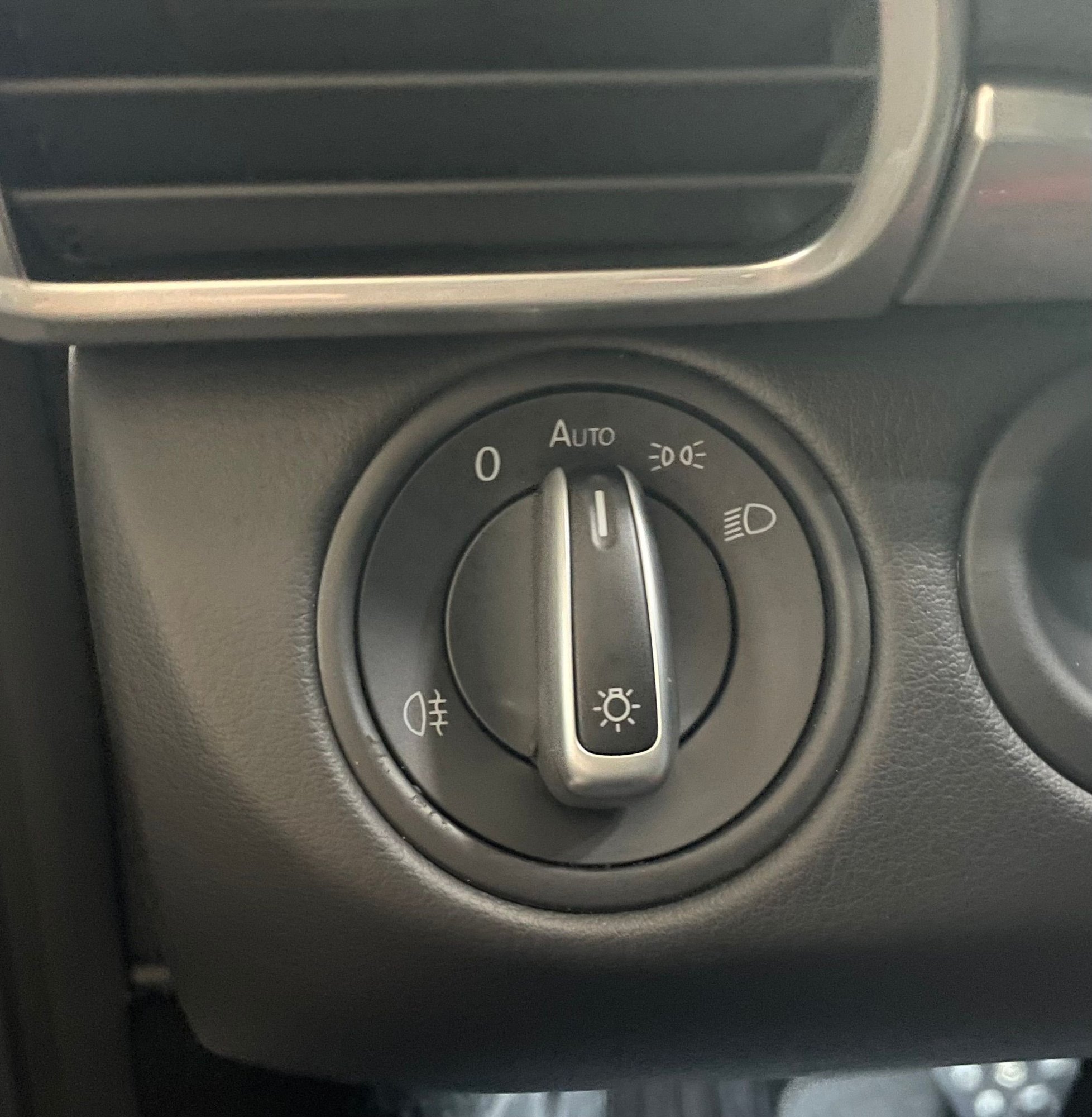
I changed the face ring from VW to the 997.1
So �Home�
shows now �Auto�
😜
fantastic idea, Knock-off VW headlight switches can be found for cheap on AliExpress. But question for @RaBe How did you get the ring over the handle of the switch? It easily pops off, but that's as far as I got.
__________________
---------------------------------------------------------------------
want automatic headlights in your 997/987?
Go to www.997research.com
While the sensor is probably unusable for our uses, it does seem to be used for the HOME function. If anyone notices, the home function only works when it's dark out. I've been able to disable the home function by shining a bright LED flashlight at the center speaker sun sensor. I've also used a diagnostic tool to see that the sun sensor status is updated on the car's CANBUS data lines. It seems to have at least 3-4 discrete levels of brightness it recognizes (at least on my Foxwell NT530) measured as W/ sq. m.
Cool, I was wondering what the car used for the home light trigger. I'd never used them before installing the auto headlight mod so I was surprised to see that the behavior varied with outside lighting.
Thanks for the idea on swapping out the light switch bezel. I found this Audi one to match the settings on my 997.2 C2S. I really liked the silver trim on the Audi version, so I just took it apart and swapped out the electronics from one to the other. I like the subtle aesthetic upgrade and the silver matches the door handles
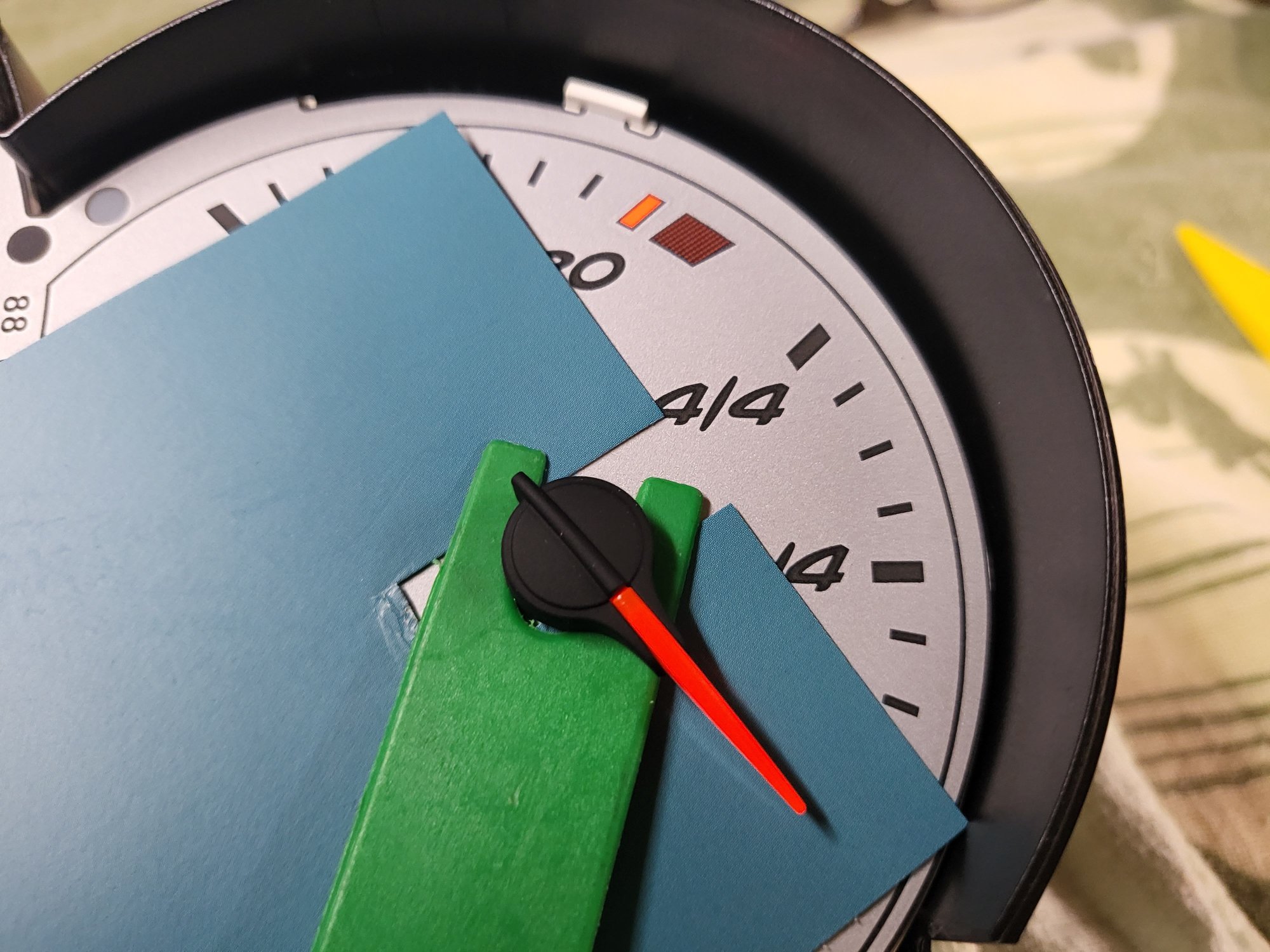
Nice gauges! Were the needles difficult to reinstall?
Nope!
It is however one item I was similarly concerned with, as there's not too much information from professionals on the needle removal process and only a few vids on gorillas swinging on stuff.
To start, the needles have neither a stop nor detent at their zero position.
The stepper motor powered function can be rotated both up and down the scale.
Thus, to remove they need to be pulled straight up, with no rotary force - using your fingers to do this might impart some rotary movement, so I cut a slot in a bank-grade card, and used a trim removal tool impart just vertical force.
They do require a bit of leverage if they've not been disturbed since manufacture.
They come off with quite a loud POP!
Putting them back on can be tricky, but aligning the needle tip with the zero marker's lower edge, then lowering the hub onto the shaft seemed to work OK for me.
The stepper motors if moved, can be felt to click softly, and if nudged, you can move back again (if you can estimate the number of clicks you just felt through your fat, nervous, fingers).
Not putting the cluster back together, and presenting the PCB with needles in space to the loom, and turning on the car, will very quickly see if the needles have moved as the stepper motors zero at this point.
If any needles are misaligned, you can remove and resinstall again aligned to the lower edge of the zero marker.
In doing instrument cluster work, removing the front lens assembly from the cluster and separating the PCBs (those pesky springs, and single-path connector tabs) takes more care and patience, but anyone who is comfortable with kitchen table electronics should have no issue with it.
No soldering, loupe, or otherwise specialist tools are needed (though removing the gauge face securing black plastic ferrules benefits from that little tool suggested, if you are going that far in).
Thanks for the detailed explanation @Kuro Neko and sorry for derrailing the thread @Hatzenbach . I promise some install pictures when I tackle this as a compensation
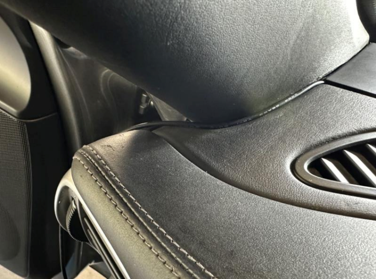
By the way, does anyone have a picture of the cable completely routed? The instructions show the routing, but they also say you should "tug it between the A-pillar and the dashboard" and I'm not sure if this is as tugged as it gets or if it should be invisible:
By the way, does anyone have a picture of the cable completely routed? The instructions show the routing, but they also say you should "tug it between the A-pillar and the dashboard" and I'm not sure if this is as tugged as it gets or if it should be invisible:
You can get it to be totally invisible. If I remember correctly, I did that by lifting the plastic panel that's on the right-hand side of your picture, closest to the windshield, and underneath it there's a hole through which you can route the cable, which you then grab from the side/below. It was quite cumbersome to route the thin cable through this tiny aperture because it was catching on something, I ended up tying it to a thin electrical cable. Hope this helps!


 02-19-2024, 11:53 AM