When you click on links to various merchants on this site and make a purchase, this can result in this site earning a commission. Affiliate programs and affiliations include, but are not limited to, the eBay Partner Network.
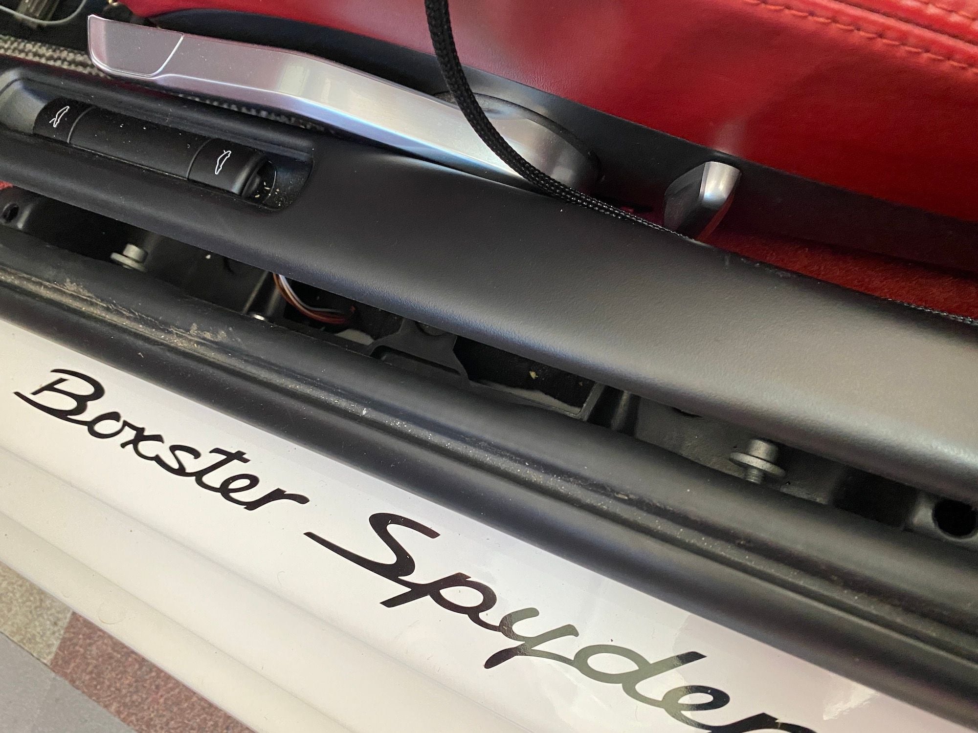
Now that you see how it works, here is my installation write-up for the PSE Always On control unit kit. My installation is for a 987.2 Boxster Spyder. In an earlier post @Soaristo has provided a link to his website showing the install procedure on a 997.2. There will be some repetition, and I plan to go into greater detail on the install process so that if this is the first project you do, that you don’t need to go to other threads to find the information.
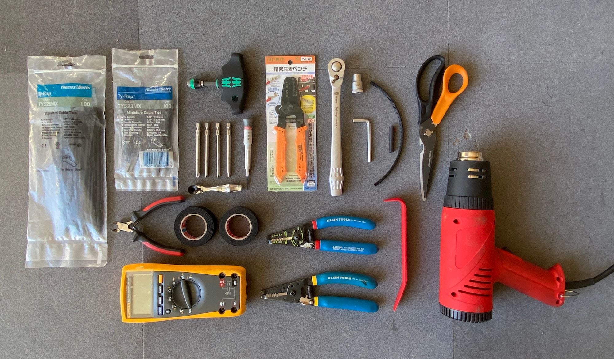
PREPARATION 1. Tools and additional supplies. You will want to get all your tools and supplies ahead of time so that the install process goes smooth. At the end of post, I will have links for where to order the tools/supplies if you are missing them.
A. Engineer Inc PA-20 / PA-21 / PA-09 Crimping Pliers. This is a must! Don’t attempt the project unless you have one of these crimpers. As you will be using only the 1.6 and 1.9 positions, any of the three will work. If you think you will have crimping needs for other sizes (smaller or bigger), make your selection accordingly. I have the PA-21 and PA-09 in my tool box. B. Wire Stripper. Needs to be able to strip a 22 and 20 AWG stranded wire. In my case I have a set of Klein wire strippers as one stops at 20 and the other starts at 22! You can get a wire stripper by Hozan (Hozan P-967) that can do both with one tool. C. Wire Cutters D. Scissors E. Electrical Tape. I recommend Tesa Tapes. There is one for interior use and another for engine bay use. They are very different. Both are excellent. F. Heat Gun G. TechFlex Flexo Clean Cut or Flexo Tight Weave cable sleeve. 1/4” dia. — at least 10 ft. I am waiting to get my new roll to confirm which one I used, as the last time I bought it was over 10 years ago to do a wiring project on my 1968 Ducati and now the product numbers have all changed. You want a tight weave to hide the wiring. I could not find these weave options on Amazon and ordered them from Cable Organizer. Another option is to use standard solid cable sleeving. H. Heat Shrink Tubing. 1/4” dia. You will need less than 6 inches. This is used to finish the ends of the Flexo cable sleeve around the wires. I. Interior Plastic Trim Flat Blade Removal tool. Highly recommended to pry interior trim. J. Ty-Rap. From Thomas & Betts. The version with the stainless steel locking insert. Top quality and professional looking. 4 and 8 inch sizes. K. Circuit Tester. I have a fancy one that reads voltages, but all you really need is one that lights up to show if the circuit is hot or not. L. 10mm Socket and Socket Wrench. This is to remove the engine panel behind the seats. M. Torx T20 and T30 Screwdrivers. For both interior and engine screw removal. N. Slot and Philips Screwdrivers. A stubby Philips is also helpful to remove the trim panel below the roll bar. O. Micro Slot Screwdriver (1mm head). Or something similar to remove the existing pins in the PSE On/Off switch wire connector in the center stack. It is also helpful to pop the caps from the trunk release rocker panel cover to access the 5mm hex screws. P. 5mm Allen Wrench. Needs to be one of these small handle-less types. Q. Optional (see later photos) — ATC Add-a-circuit Fuse Tap holder. I have another device I installed previously (for Bluetooth streaming of music on the stock radio) that needed ignition-on power and instead of search for another free location, got one of these to have both the Bluetooth and PSE work on the same circuit. It works perfectly.
Tools and Supplies
INSTALLATION 1. If you do it in one sitting, it will take about 2 hours or so. It took longer for me as I am experimenting with this install for the first time. You can also do it in stages as there are four distinct procedures to perform. My instructions will break it down by the four sections. 2. Control unit location. You should decide this first. When you get your kit, do a rough run of the wiring harness from the PSE Vacuum Valve in the Engine Bay to the Interior (you can just lay it out on the top of the engine bay cover). I’ve asked @Soaristo to add more length to this wiring harness to give greater flexibility in the placement of the control unit. I prefer the unit to be hidden, so I considered two locations — behind the Fuse panel or behind the Center stack. For my install, I decided on the Fuse panel location. 3. Make sure the ignition switch is in the OFF position when doing the installation. For extra safety, you can disconnect the battery. 4. Read the direction before you do anything and reread them again as you proceed.
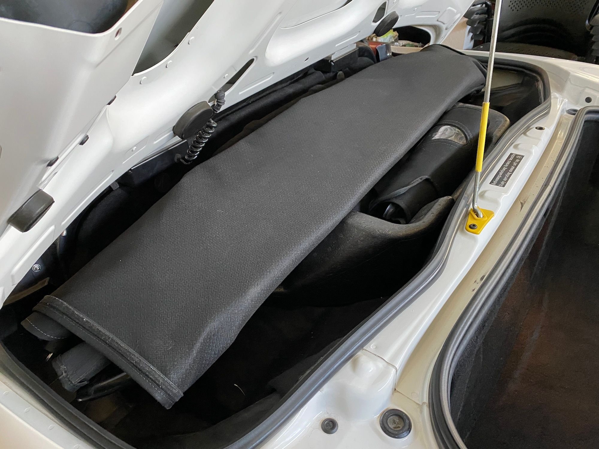
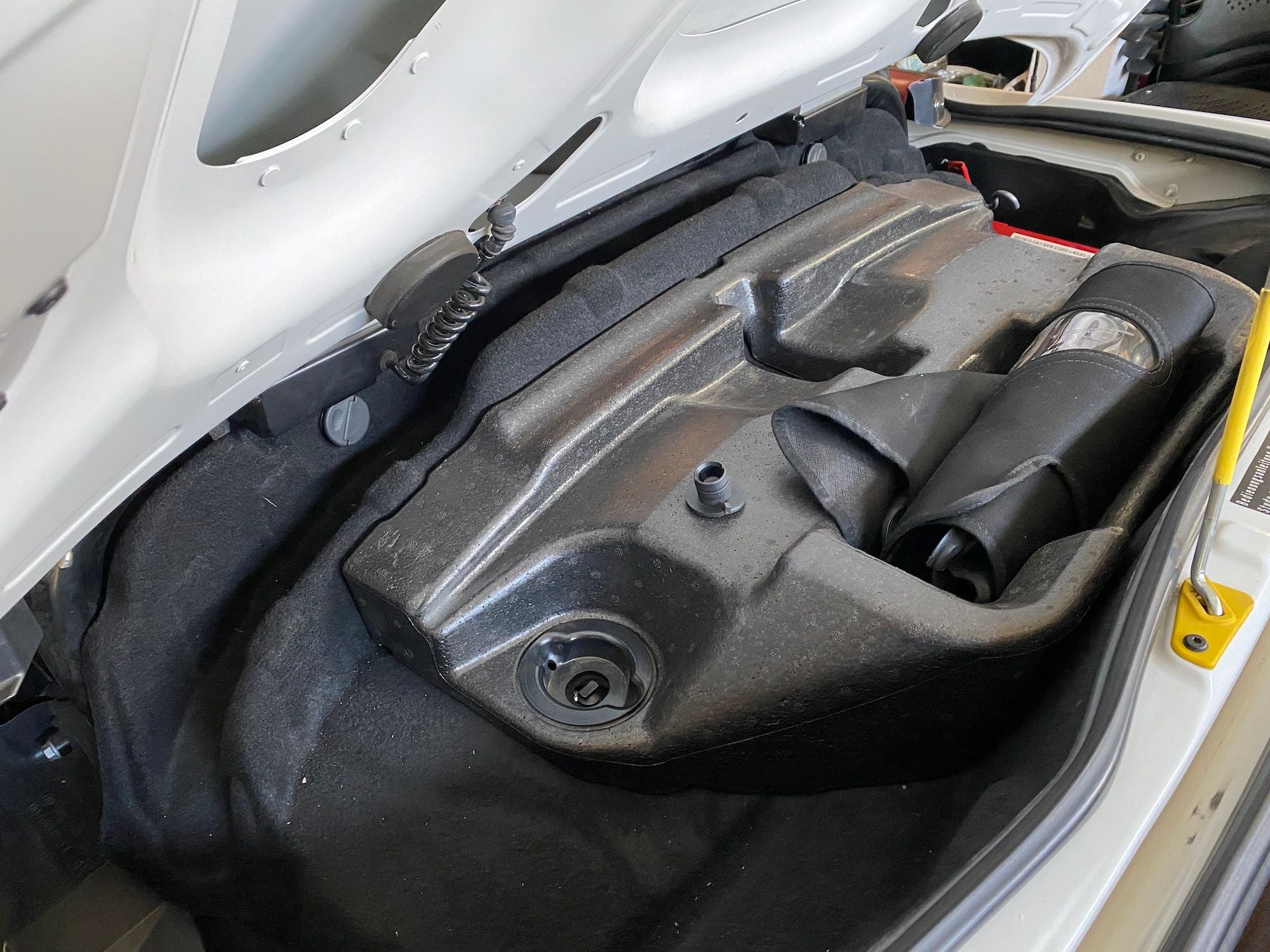
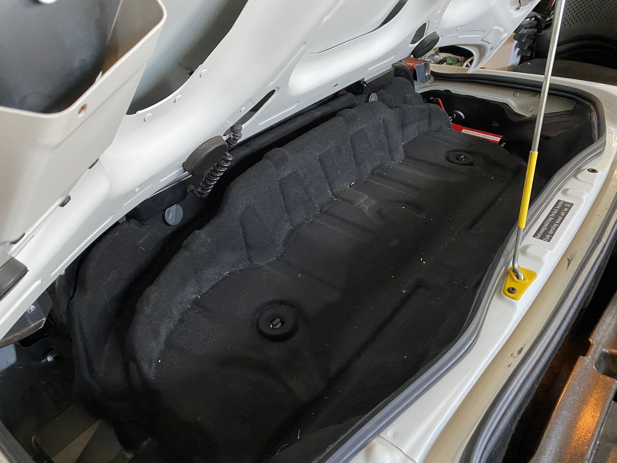
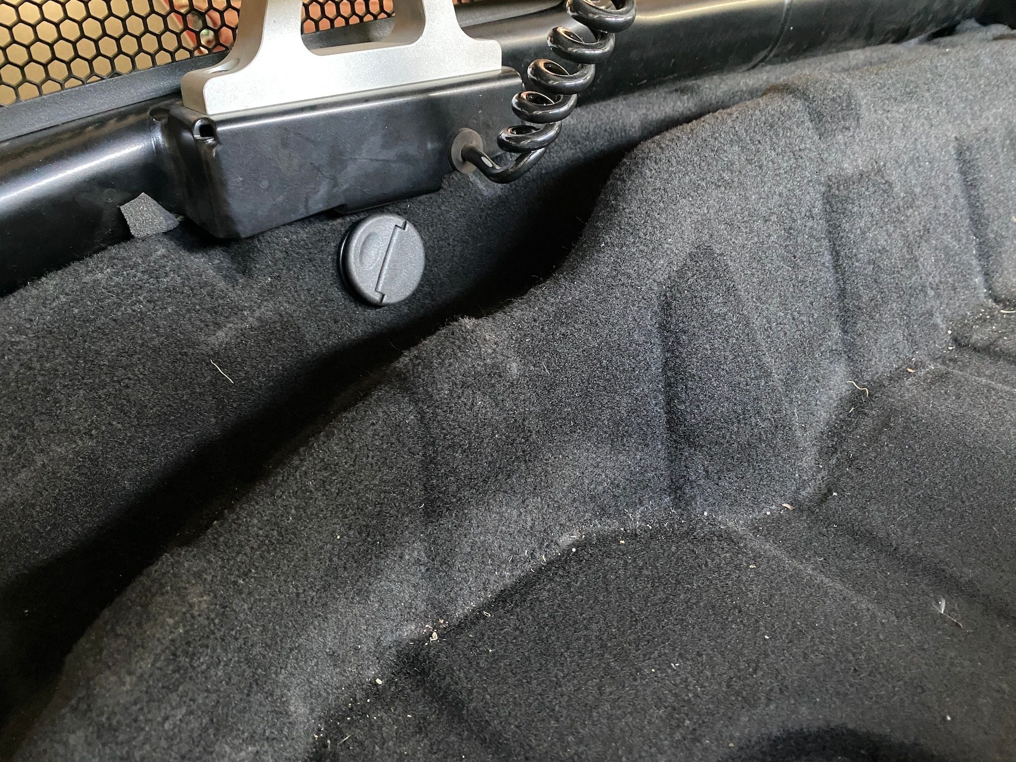
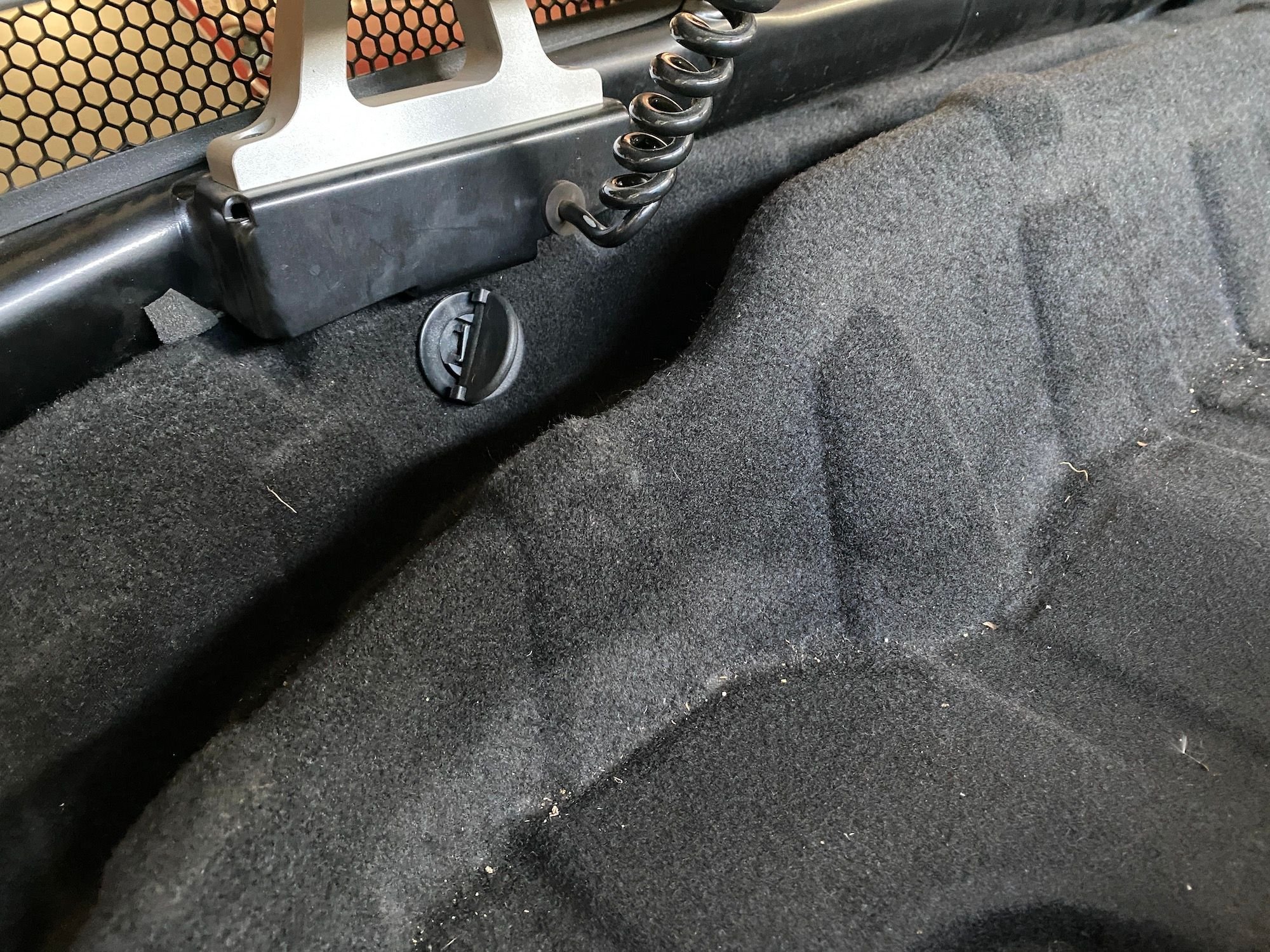
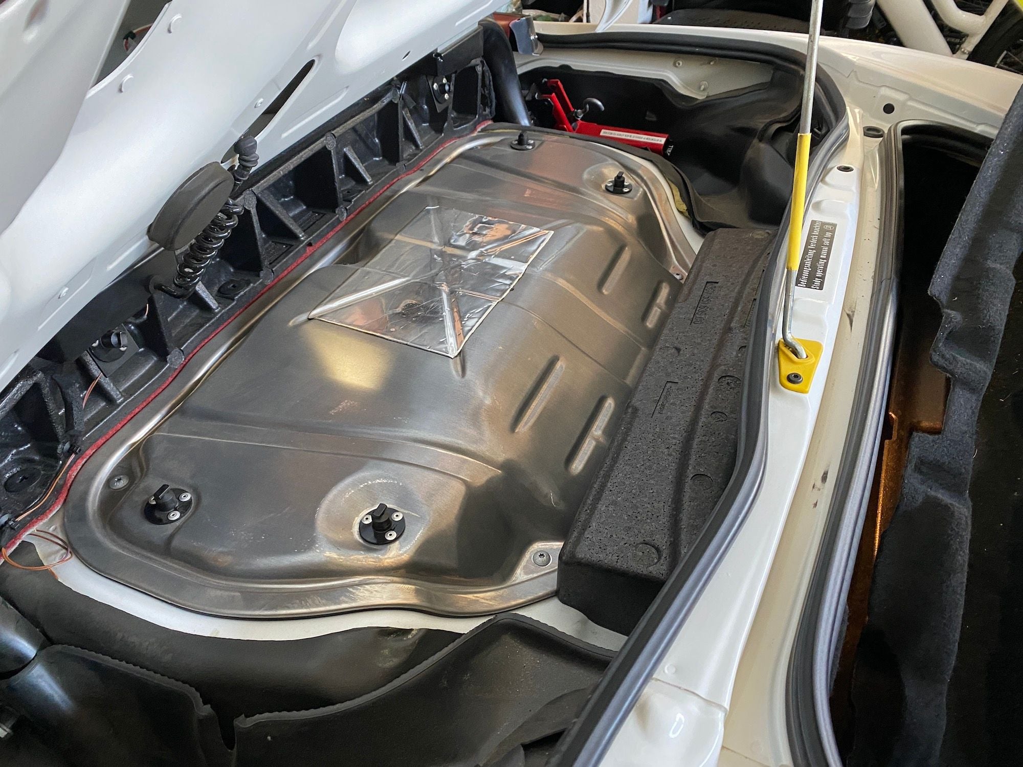
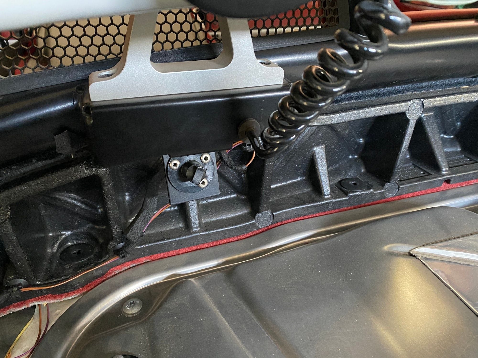
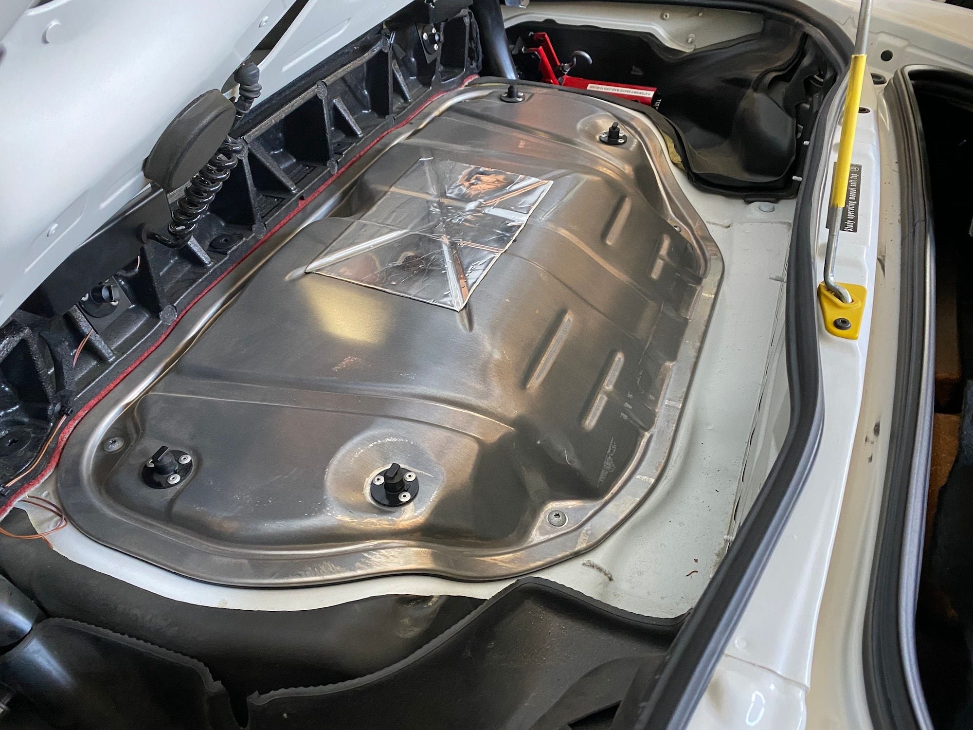
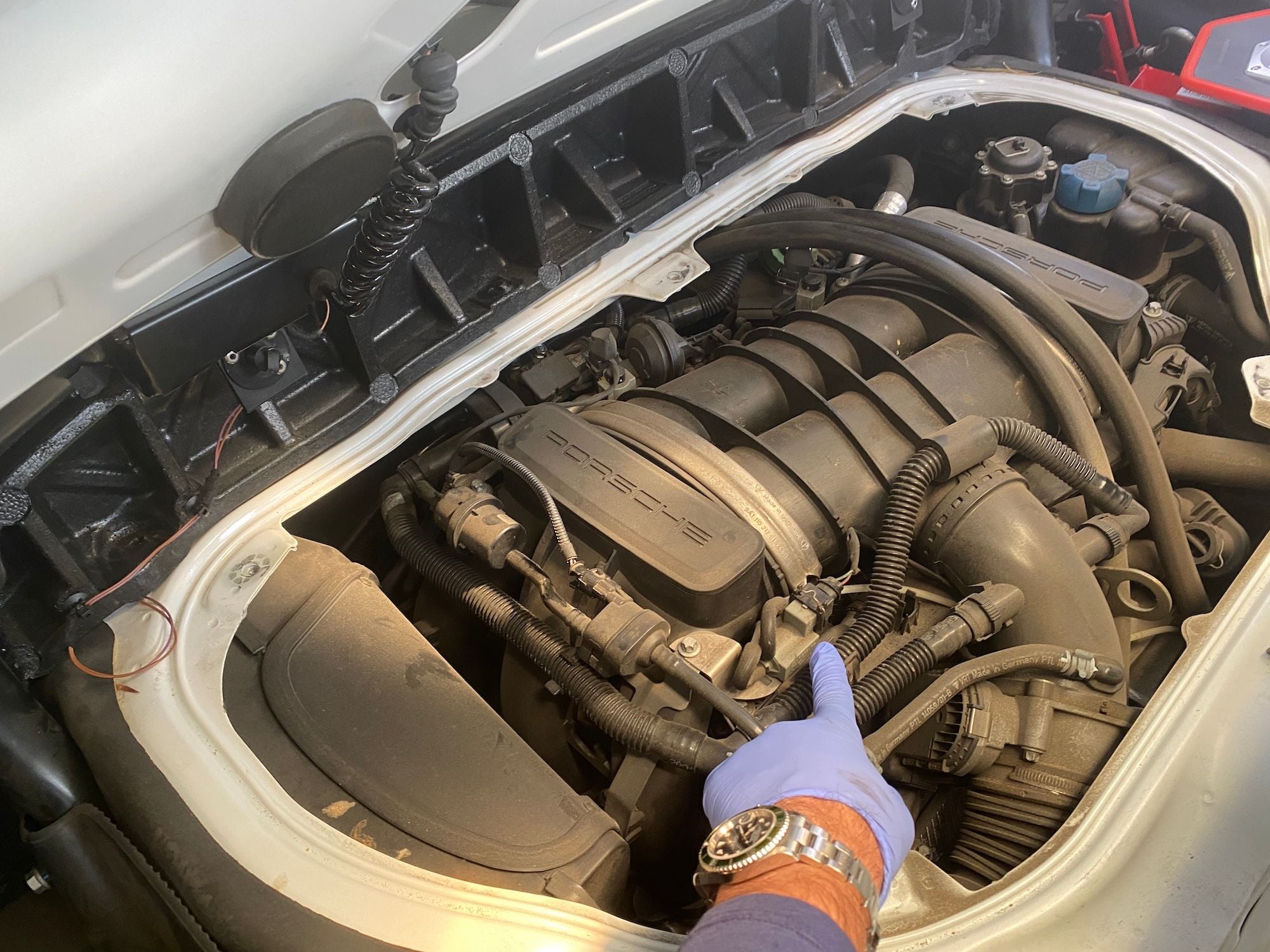
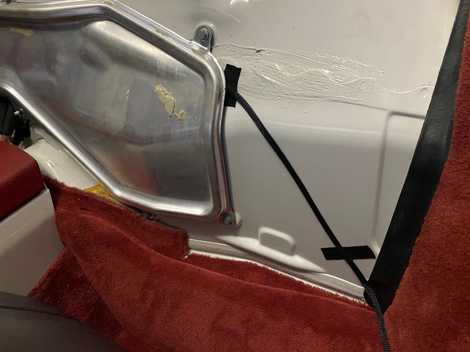
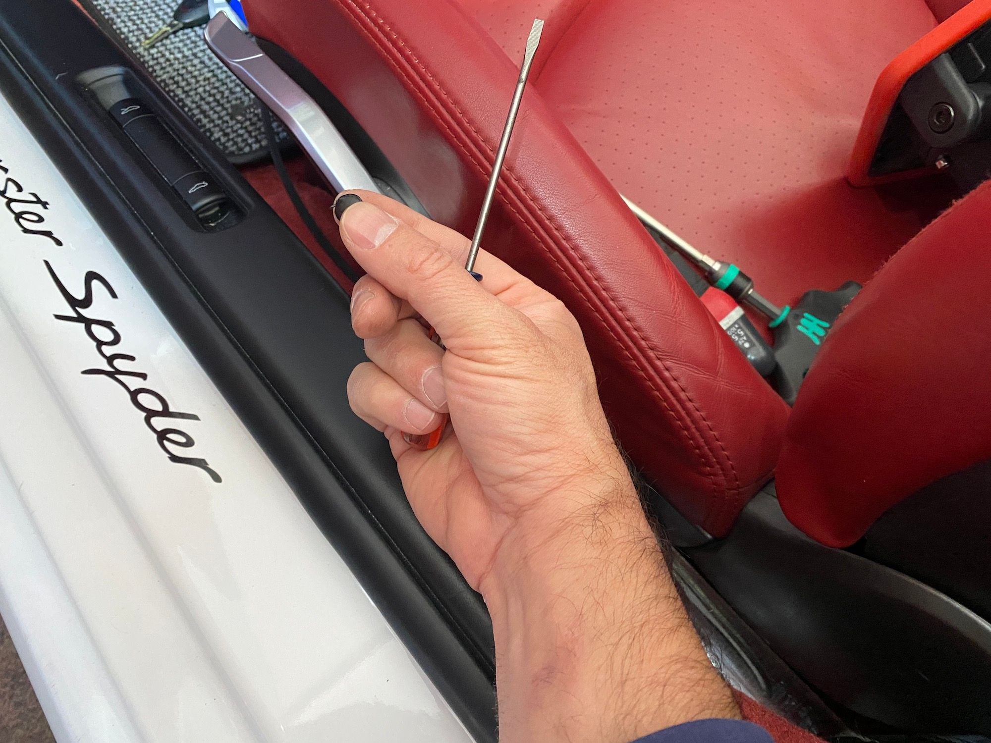
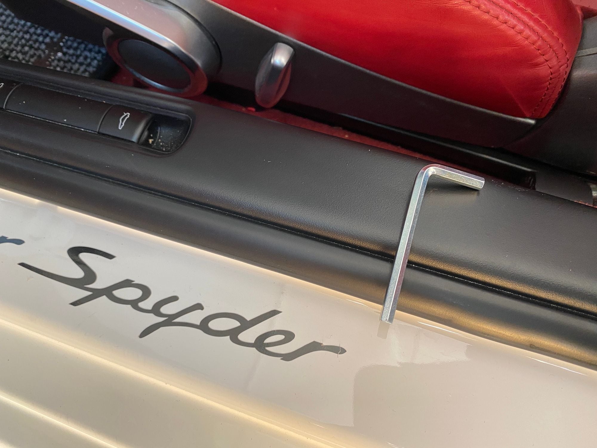
INSTALL PART ONE — ENGINE BAY 1. Open the rear cover and secure with the holding stand. 2. Remove the bikini top and then remove the styrofoam tray below. There are two lift, twist and pull connectors — one on each side — that need to be removed first. 3. Remove the soft-trim panel. There are two lift, twist and pull connectors — one on each side at the bulkhead — that need to be removed first. The other side of the trim is held by the rubber seal. Just push the trim away from the seal. 4. Remove the styrofoam block. Note the orientation of the block. 5. Remove the styrofoam trim panel at the bulkhead below the roll bar. There are 4 plastic pin connectors that secure this panel. You will need to rotate the connectors counter-clockwise to loosen them (a stubby Philips screwdriver helps) and then insert a Slot screwdriver at the base of the connector and push up to release the connector. You can then lift up and out the trim panel. You do not need to remove the wires that are connected to the panel. 6. Remove the engine panel. You will need the T30 screwdriver for the 5 screws. You should now be able to see the PSE Vacuum Valve. It’s the gray colored part just behind the intake cover and with a black connector attached to it. To remove the black connector, push down on the metal clip, then pull the connector away from the valve. I used a Ty-Rap to secure the connector to the wiring loom directly behind the valve. Do this after you have installed the new connector so that it does not get in the way. 7. Now go to the interior and remove the carpet panel behind the seats. The top of the panel is secure by the 4 screws at the top. Lift and then remove the panel. 8. Remove the interior engine panel. You need the 10mm socket and socket wrench. There are 8 bolts. This is where you need to decide which direction to go — through the center console or the rocker panel. I went with the rocker panel direction and positioned the wiring harness in a location that would limit the compression on the wire when the engine panel is secured. Adding the Flexo sleeve to the wires helps as well to keep the wiring from getting damaged. An alternative is to drill a hole in the bulkhead and then add a rubber grommet through which to run the wiring harness and circumvent the engine panel completely. I did not want to make any new holes in the sheetmetal, so that was not an option and I could not find any other existing holes to run the wiring harness. 9. Run the new PSE Valve Connector wiring harness. First I added the Flexo sleeve and secure it with the heat shrink tubing on the connector end only. Plugged the connector into the PSE Valve and ran the wiring harness along the existing wiring loom, later securing it with Ty-Raps. Run the wiring harness to minimize any chance of contacting any hot locations on the engine itself! 10. In the interior use the Tesa tape to secure the wiring harness to the bulkhead and continue to run the wiring harness down to the rocker panel. 11. Remove the two caps from the trunk release rocker panel cover. Use the micro slot screwdriver and be slow and gentle to not damage the caps. 12. Use the 5mm hex tool — long side goes in — to loosen (just a few turns is enough) the two screws. You may need to move the seat forward or back to allow access. Then just lift up to remove the trunk release rocker cover panel. 13. Take the wiring harness and run it under the carpet — between the door seal -- and through the rocker panel area, until you reach the carpet panel that covers the Fuse panel. 14. Reinstall the trunk release rocker panel cover. Just the reverse of Steps 11-12. 15. Reinstall the interior engine panel, being careful around the location of the new wiring harness. 16. Reinstall the carpet panel and then the trim panel. The pin connectors just need to be pushed down to secure the pins. 13. Go back to the engine bay -- use Ty-Raps to secure the wiring harness and the existing factory PSE connector. 14. Reinstall the engine panel, the styrofoam block, the soft-trim panel, the styrofoam tray and bikini top. Just the reverse of Steps 2-6. 15. Close the rear cover.
S2-A. Remove Bikini Top.
S2-B. Remove styrofoam tray. There are two lift, twist and pull connectors -- one on each side.
S3-A. Remove soft trim tray. There are two lift, twist and pull connectors on the bulkhead -- one on each side.
S3-B. The lift, twist and pull connector -- locked position.
S3-C. The lift, twist and pull connector -- flap lifted up, now twist.
S4. Remove the styrofoam block.
S5. Here are the two Pins holding the styrofoam trim panel below the roll bar. There are two more on the other side.
S6. Remove the engine panel.
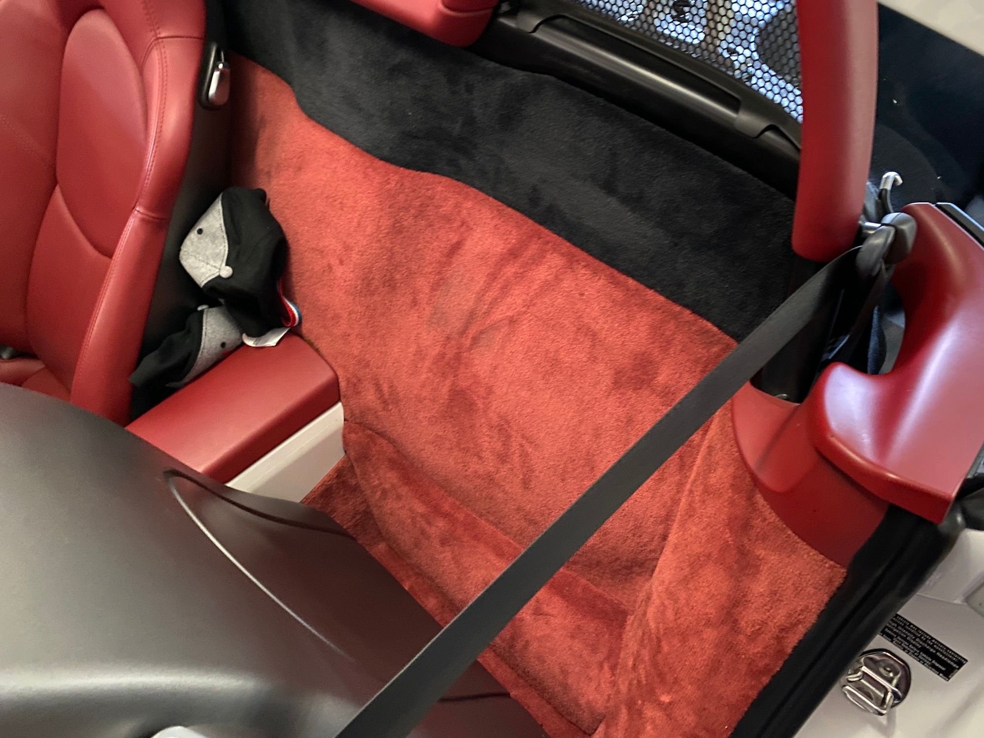
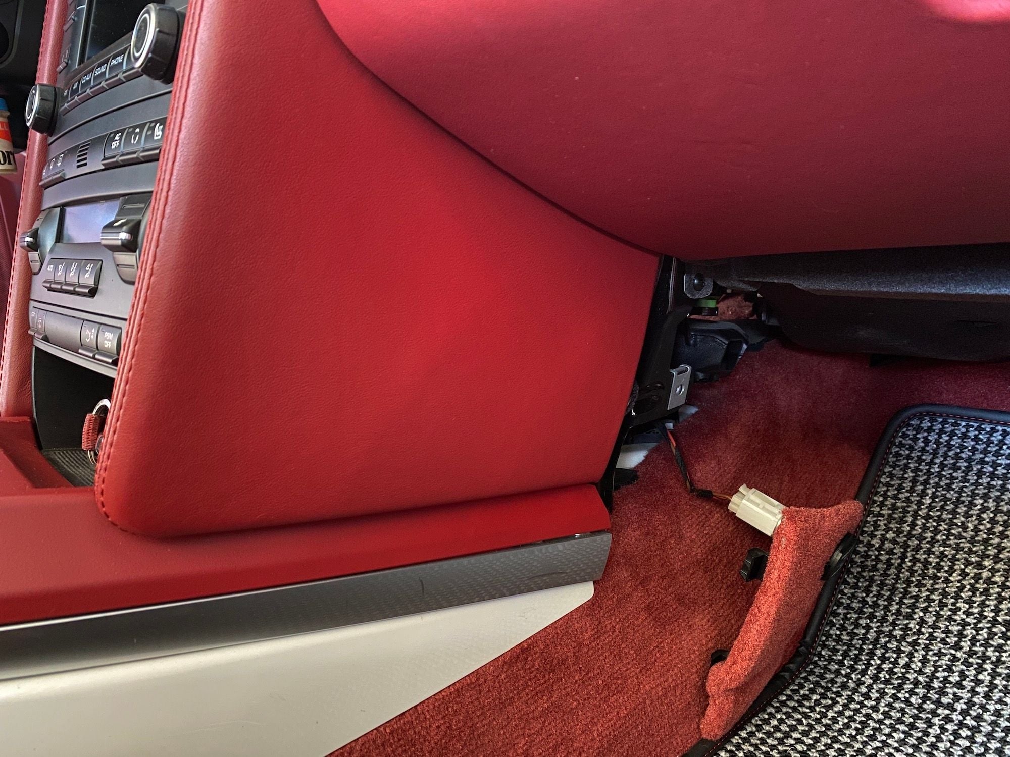
S7. Remove the carpet panel behind the seat.
S8. Remove interior engine panel.
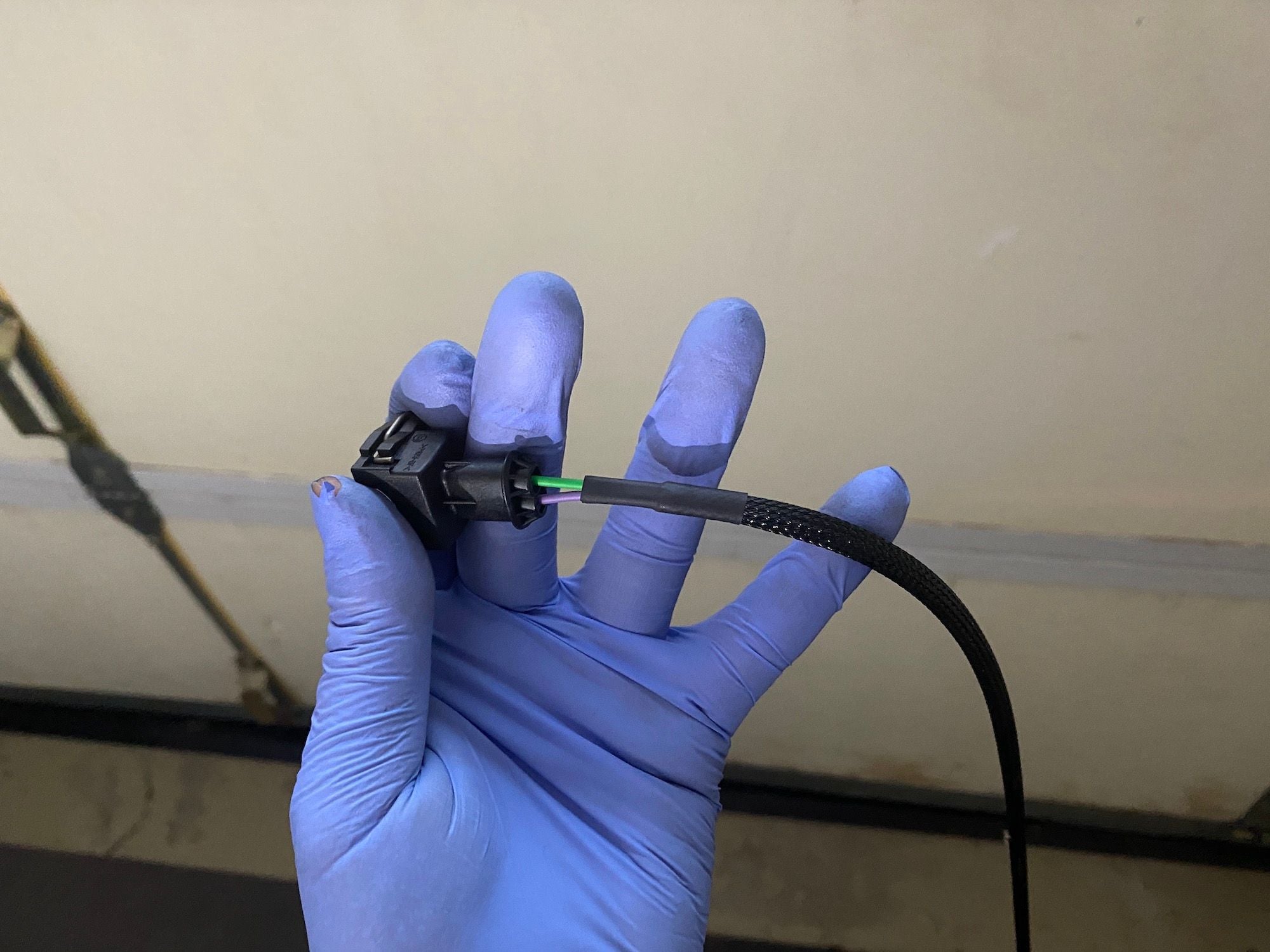
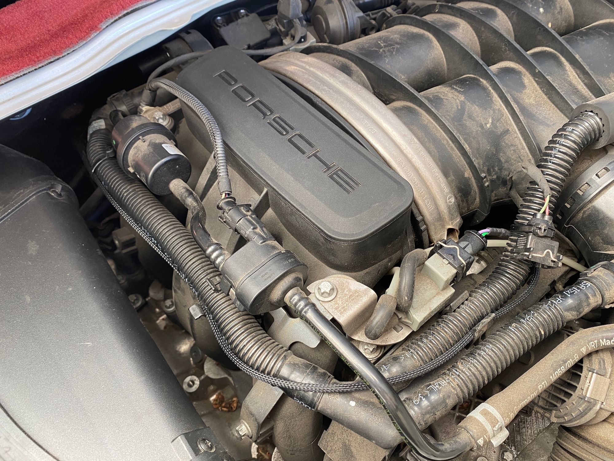
S9-A. PSE Valve Connector wiring harness with Flexo sleeve.
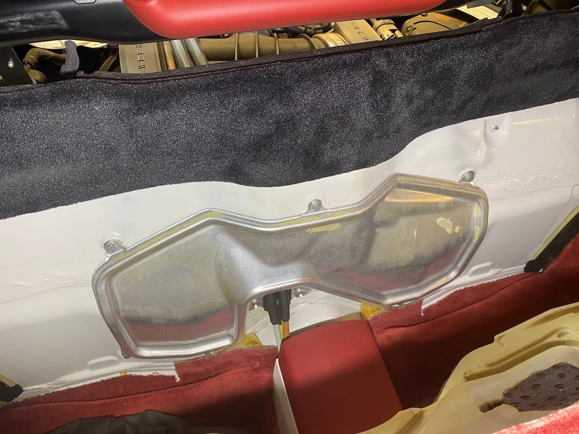
S9-B. I am pointing to the PSE Valve Control.
S10. Secure the PSE Valve Connector wiring harness with Tesa tape.
S11-A. One of the two caps that need to be removed to access the hex screws inside the Trunk Release rocker panel.
S11-B. 5mm hex wrench. You only need to loosen the screws.
S12. You can see the two hex screws.
S13. Use ty-Raps to secure the wiring harness and existing PSE connector.
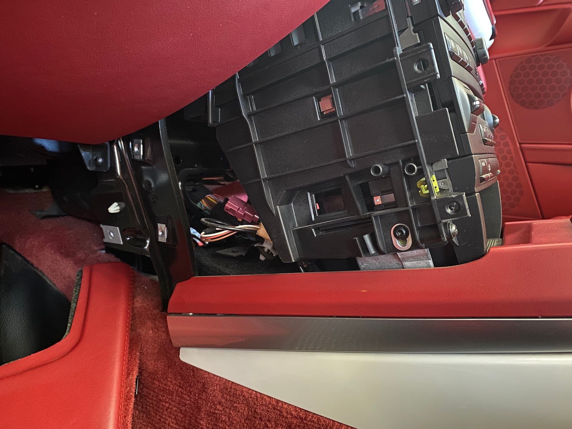
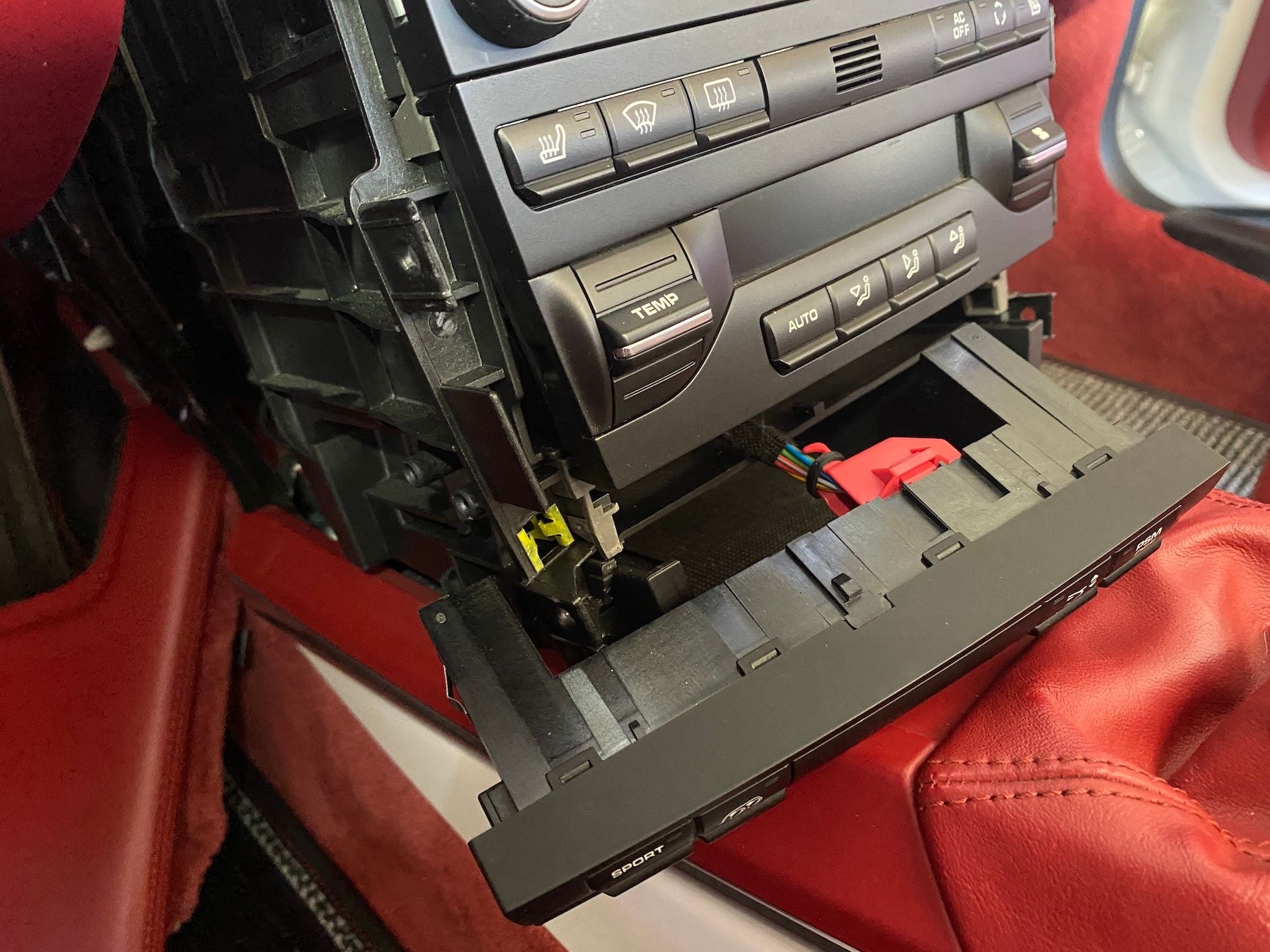
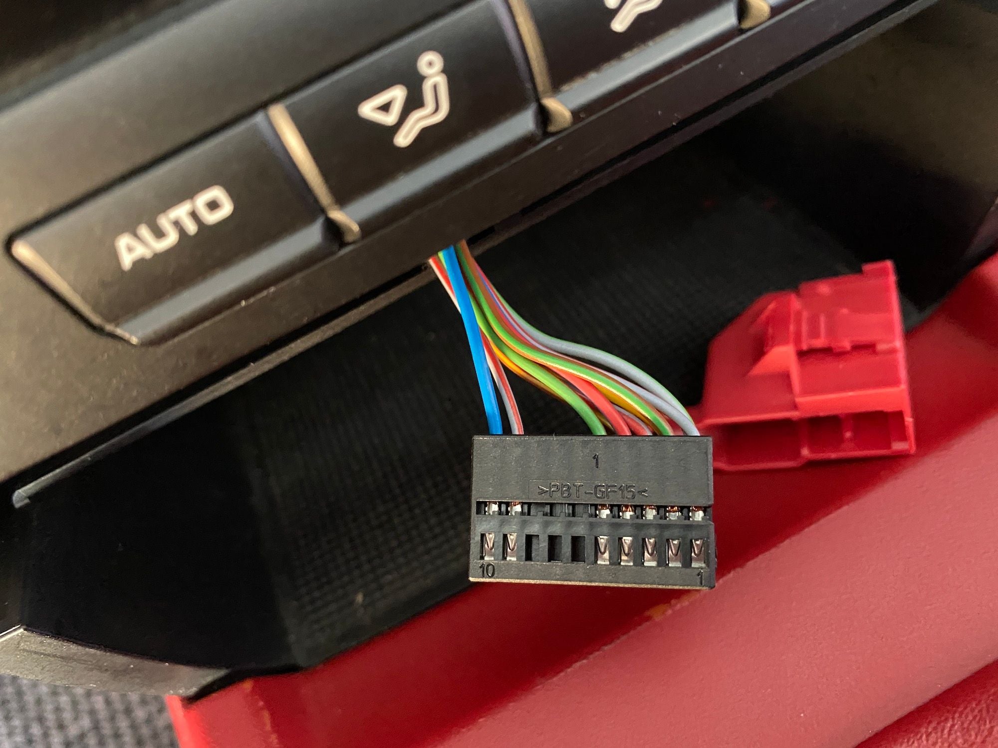
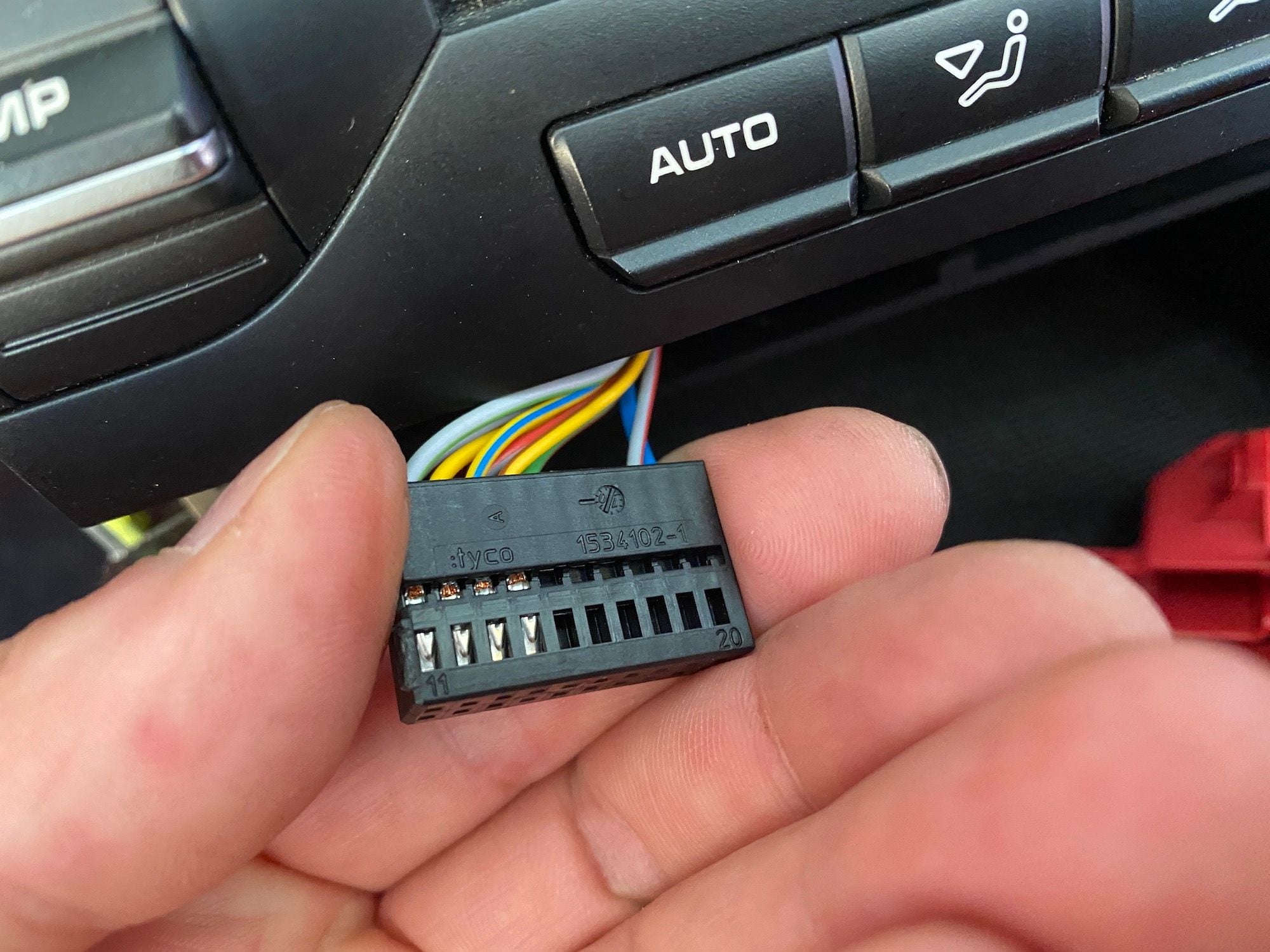
INSTALL PART TWO — CENTER STACK 1. Remove the two carpet trim panel on both sides. You will need a T30 screwdriver for the hidden screw. 2. Remove the two center stack side panels on both sides. You will need a T20 screwdriver for the two screws on both sides. Once the screws are removed, pull the side panel towards the direction of the gear shift and up to release them the plastic connectors. If necessary you might need the Plastic trim panel pry bar for assistance. 3. The PSE switch is part of the Combined switch panel. The whole panel will come out. To do that, press IN on the metal tabs on both sides of the switch panel and pull the panel towards you. Yo might need to go behind the switch panel to adjust the wiring loom so that it does not restrict pulling the switch panel out. It does not come out very far! 4. Remove the Red covered connector from the Combined switch panel. Set aside the switch panel. Remove the Ty-Rap from the red cover and then remove the red cover to access the connector and wires. There is a tab on the side of the Red cover that needs to be pushed IN for the red cover to come off. Use the micro slot screwdriver. 5. Since you should already have the PSE installed, there are existing wires in the locations (A10 and A11) you want to replace with the Blue/Gray wiring harness from the kit. The switch panel connector is marked so you can find the location of pins A10 and A11. They are at the opposite ends of the connector. Using the micro slot screwdriver to push on the visible part of the metal pin and pull the wire out at the same time. You may need to keep pressure on the pin throughout the removal process. Use Tesa tape to cover the ends of the removed connectors and set the wires aside. 6. Based on where you plan to locate the control box, cut the length of the Blue/Gray wiring harness to fit, with some extra length (4-6 inches is good). Then cover the wire with a Flexo sleeve — about 2-4 inches shorter than the wire length — and secure both ends with heat shrink tubing. Allow enough wire lead at the cut end to strip and crimp the pin connector. 7. Then make the pin connections on the end for the PSE On/Off switch. The pin connector you want to use is the E-1 (longer pin). Strip the wires — just a little bit — using the 22AWG stripper. Position the E-1 pin connector onto the wire making sure the bare part of the wire is located at the middle crimp location and that the covered part of the wire is located at the end crimp location. Use the PA-20/21/09 crimper at the 1.6 position. Follow the orientation and directions on the package that came with the crimper. The crimp arms that will secure around the wire should be facing UP as you crimp down to secure the connection. After making the middle crimp, move to the end location and using the 1.9 position, crimp the connector to the covered wire. Repeat for both wires. 8. Look at the pin connector and notice the side that has a lifted metal flap. This is the side that will be visible when in the switch panel connector. You just need to slide the pin connector into the switch panel connector slot until you hear it lock in. Do this for both wires. The Blue goes into the A10 slot and the Gray goes into the A11 slot. 9. At the PSE On/Off switch panel connector end, group the wires together and put back on the Red cover, it will snap into place. Use a small Ty-Rap to secure the wires to the red cover. 10. Connect the switch panel connector to the Combined switch panel and push the panel back into position. 11. Reinstall the Center stack side panels and the carpet trim panels. Just the reverse of Steps 1-2.
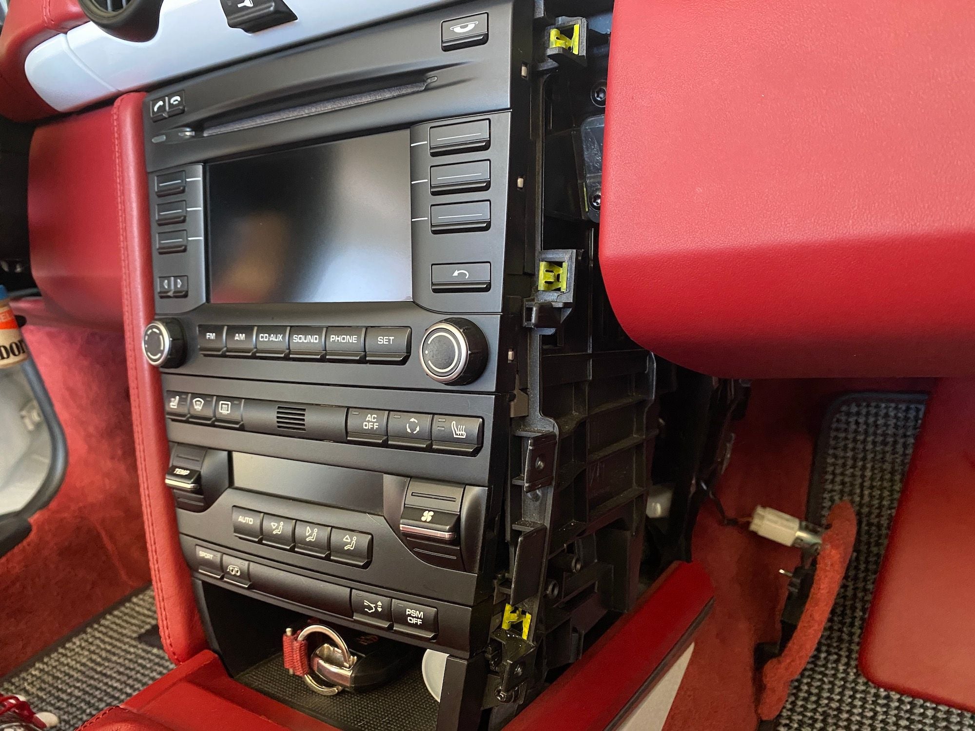
S1+S2. Right side Carpet trim panel removed. Use a T30 screwdriver. Then remove the two screws holding the Center Stack Side panel. Use a T20 screwdriver.
S2. Center Stack Side pane removed.
S3-A. Push on the metal clip of the Combined Switch panel -- one on each side -- and pull the switch panel away from the center stack.
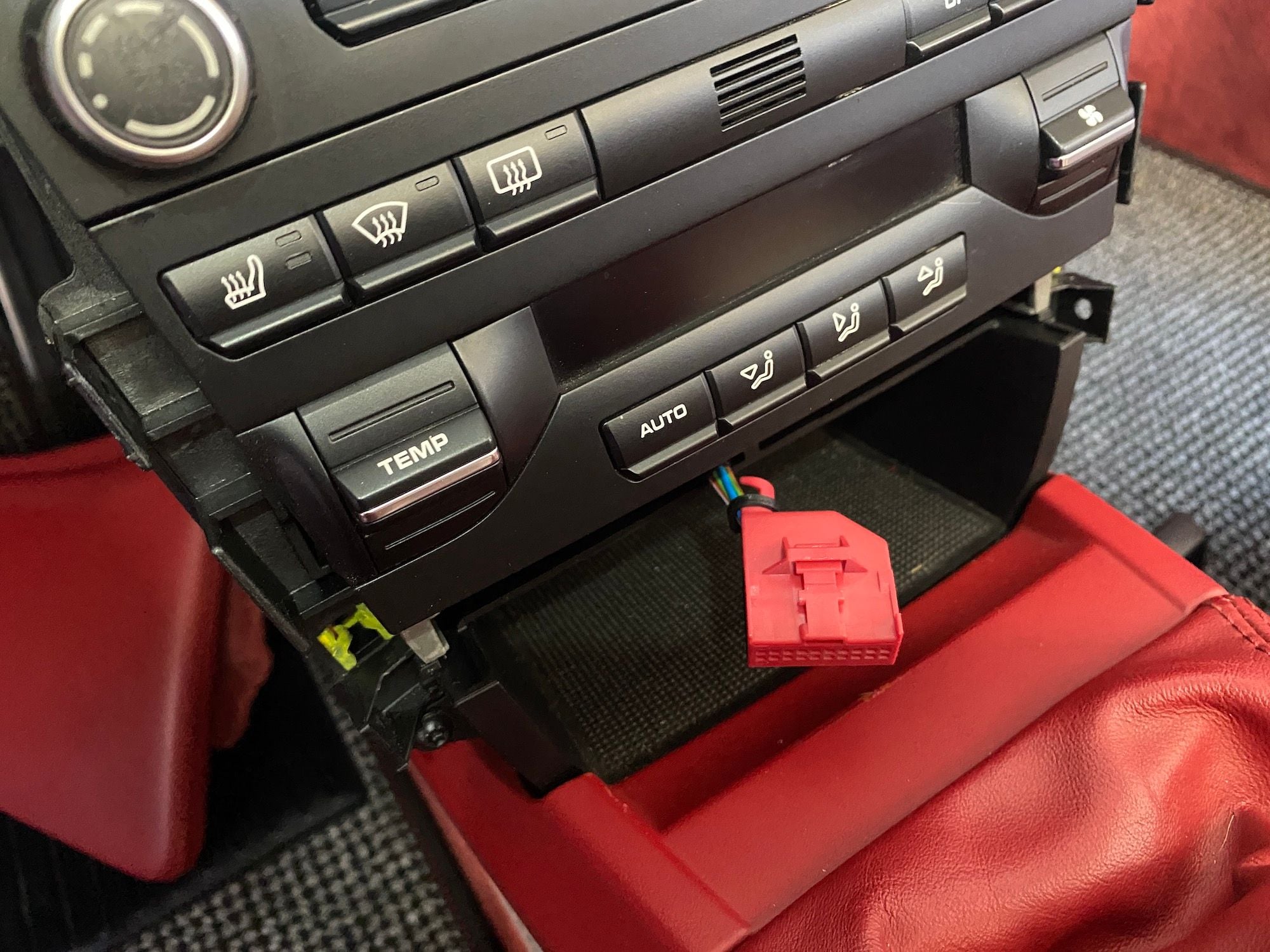
S3-B. Combined Switch panel removed.
S4-A. Connector released from the Combined Switch panel.
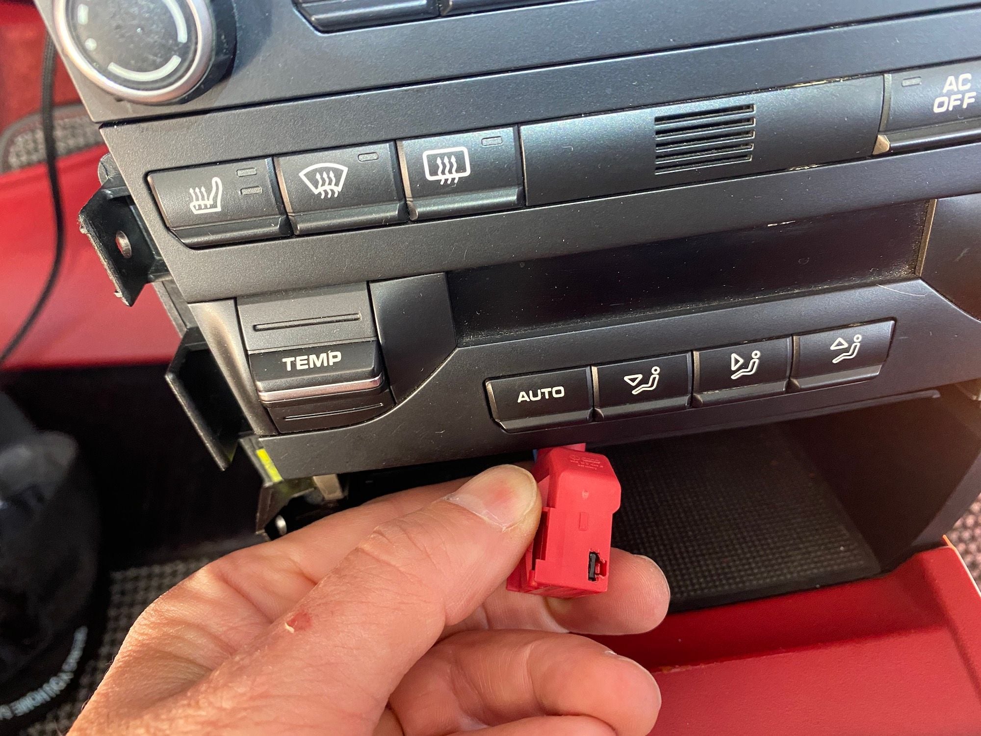
S4-B. Location of the tab to push in to be able to release the connector from the Combined Switch panel.
S4-C. Red cap removed from the Combined Switch connector.
S5. You can see the Pin numbers marked on the connector.
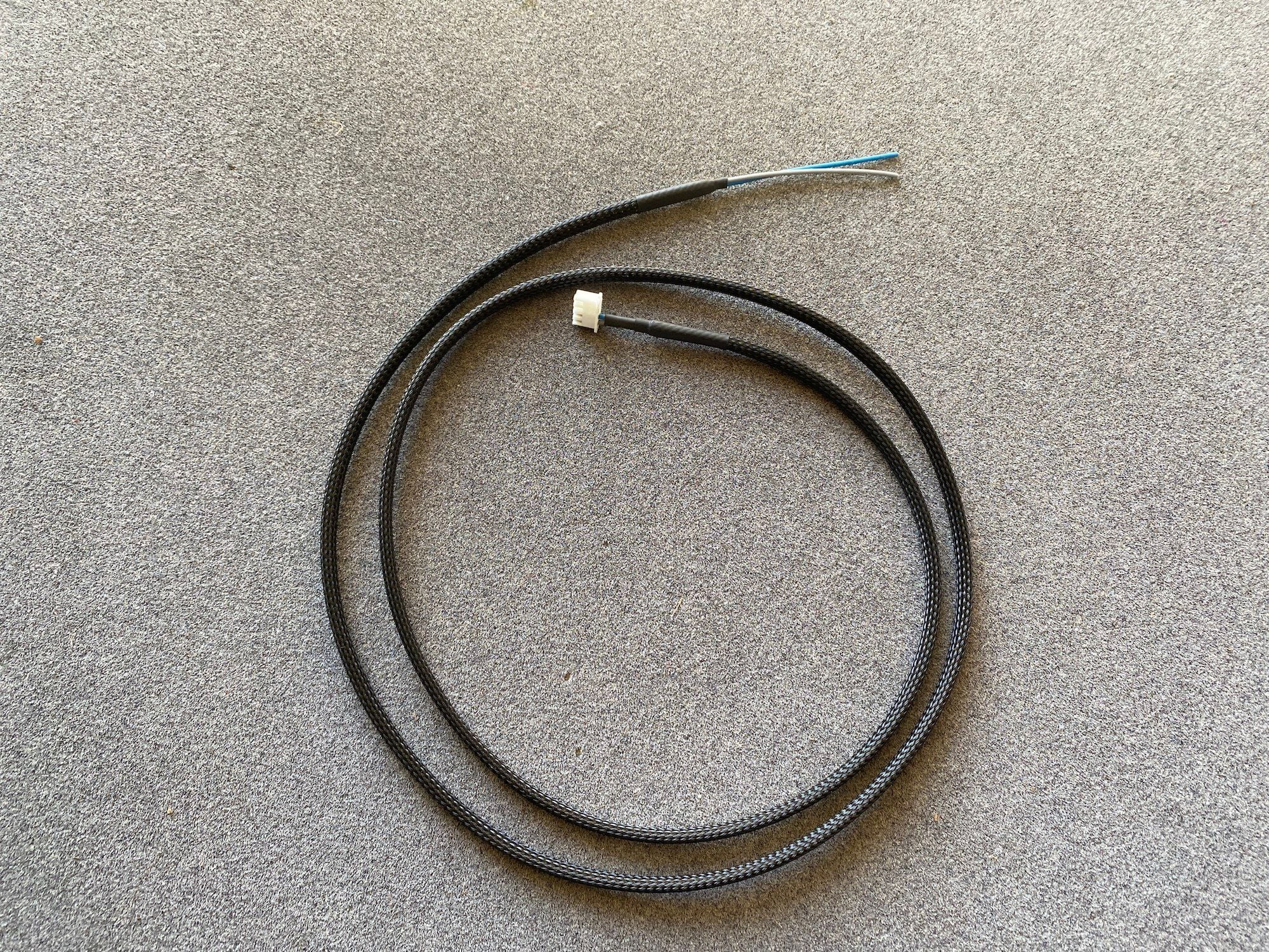
S6. PSE On/Off switch wiring harness with Flexo sleeve installed.
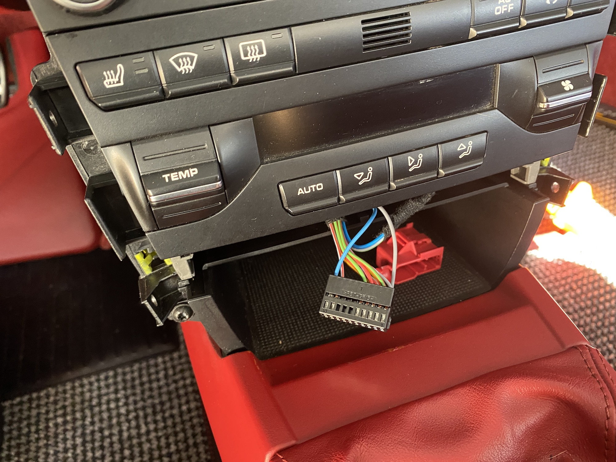
S8. New wiring harness installed.
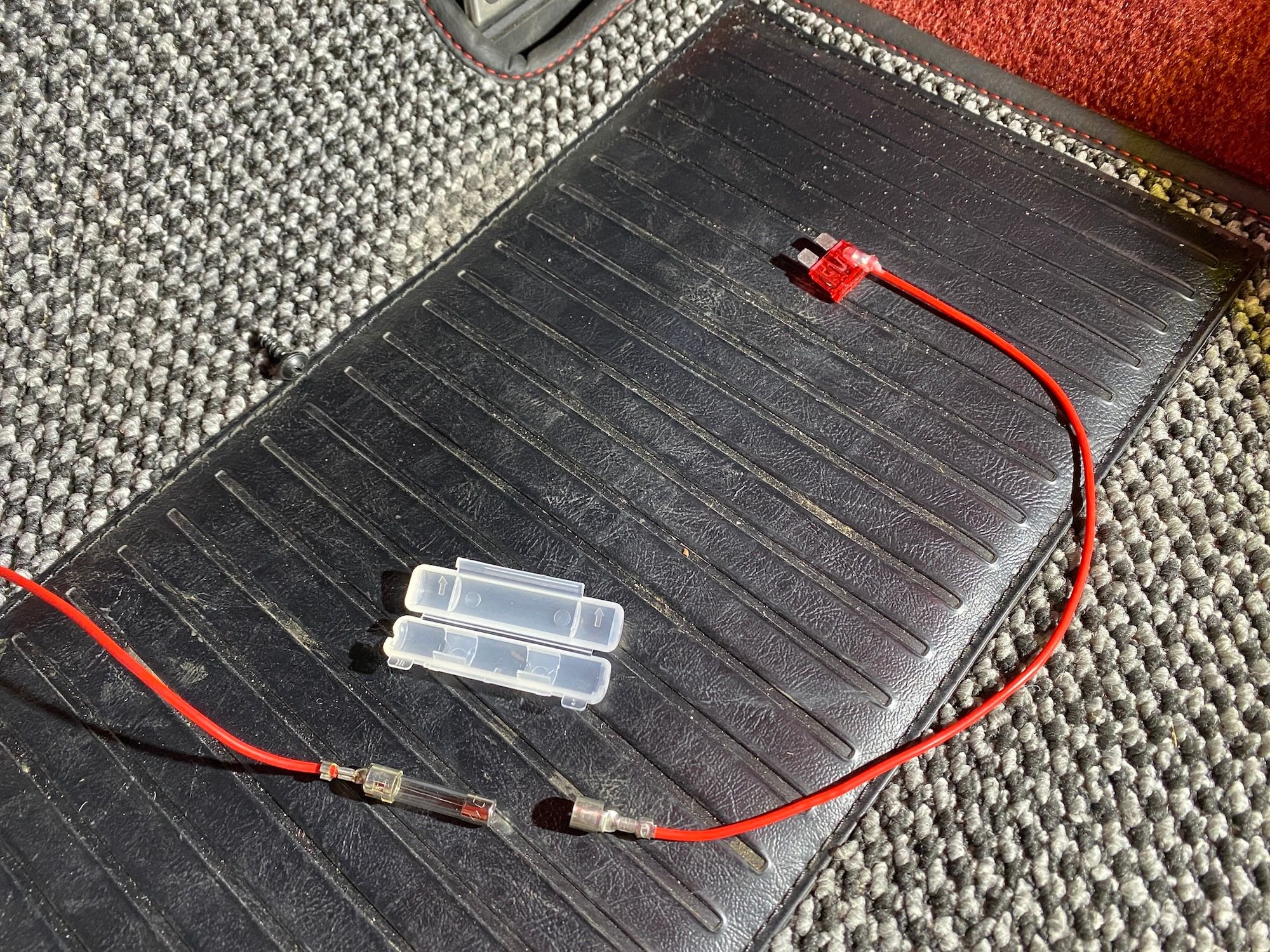
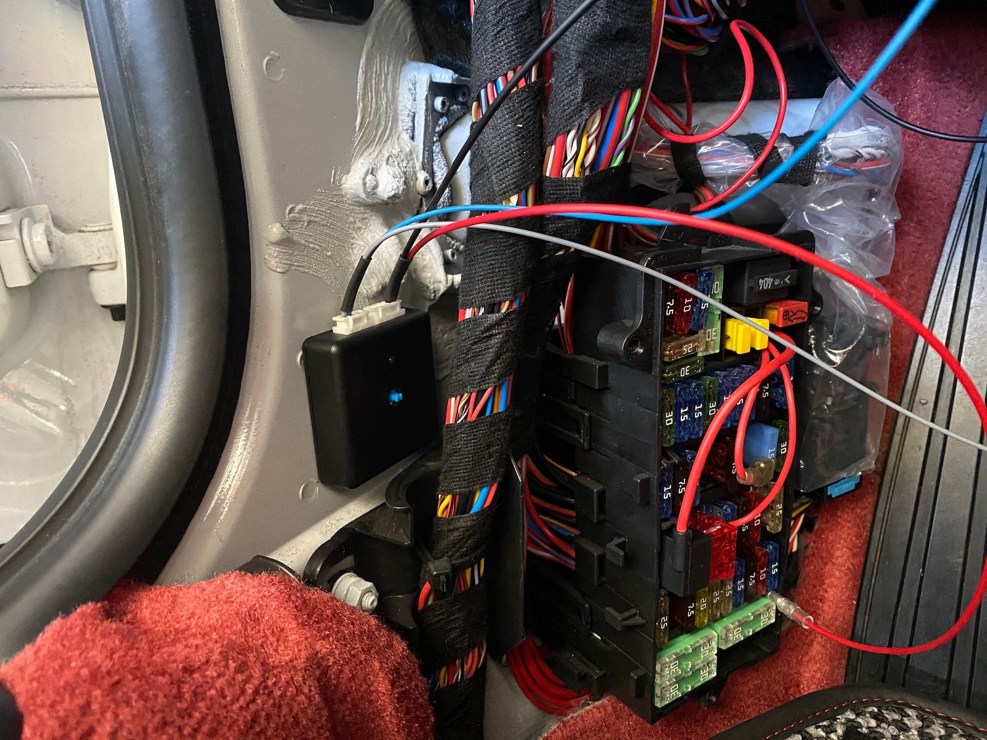
INSTALL PART THREE — FUSE BOX 1. Pop open the fuse panel cover and set it aside. 2. Using a Philips screwdriver, remove the three screws holding the carpet panel around the Fuse box. Pull the panel away starting from the bottom and set it aside. 3. Install the Power lead wire. This is attached to an ATC fuse and also has a separate 3A Post fuse in line. You will position the ATC fuse at the C1 location in the fuse box. C is the third bank of fuses from the bottom. And 1 is at the left edge. The wire coming out of the fuse should be at the BOTTOM position — you want the 3A Post fuse to blow first. To keep the wires tidy, you want to run them through a hole in the fuse box just below the RED fuse cover with the icon of the car in the upper right of the fuse box. In order to run the wire through the hole, you will need to disassemble the 3A Post fuse section. Press in on the center section of the 3A fuse cover to release the cover. Pull one end of the wire (the side with the ATC fuse) off the 3A fuse. Thread the Power lead wire through the hole and reassemble the 3A Post fuse holder on the back side of the fuse box. 4. Install the Ground wire. There are multiple places, use your Circuit Tester to check where there is a good ground connection. I used the screw at the steering column to locate the ground wire. Easy access. Just loosen the screw enough to slip in the ground connector. You will need the T30 screwdriver.
S3-A. Power lead with 3A Post fuse removed.
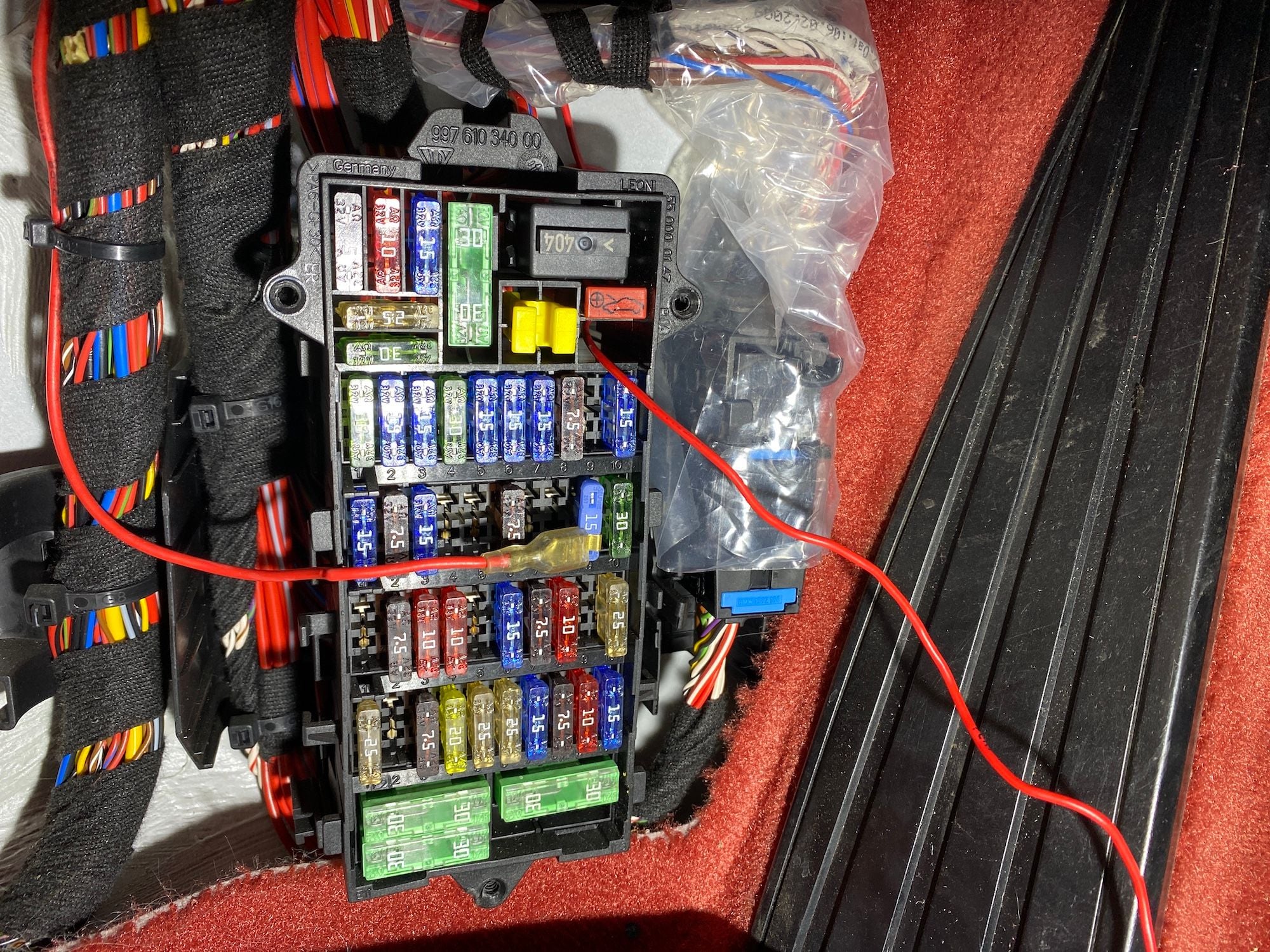
S3-B. The Power lead wire (red wire on the right) being threaded through the back of the Fuse box. Note the open fuse position of C1.
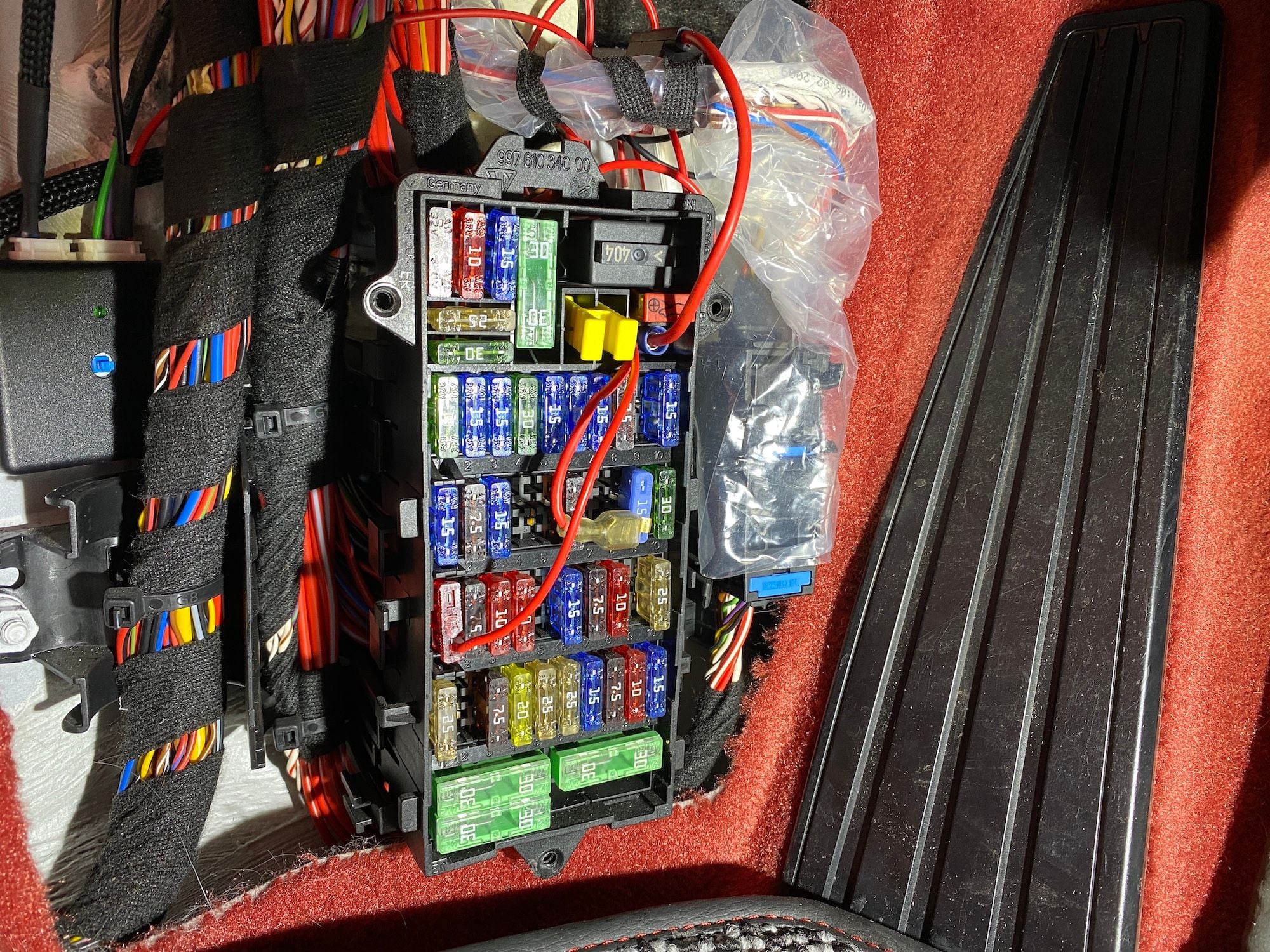
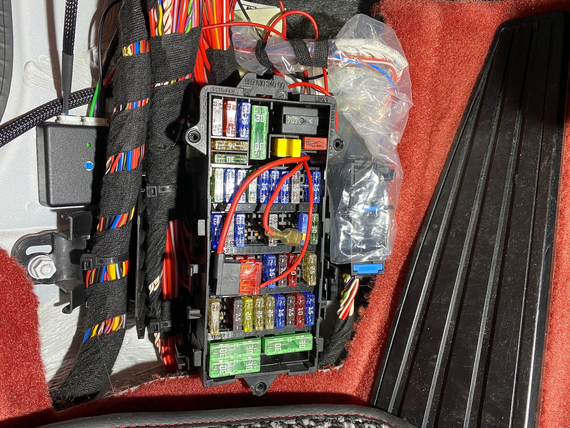
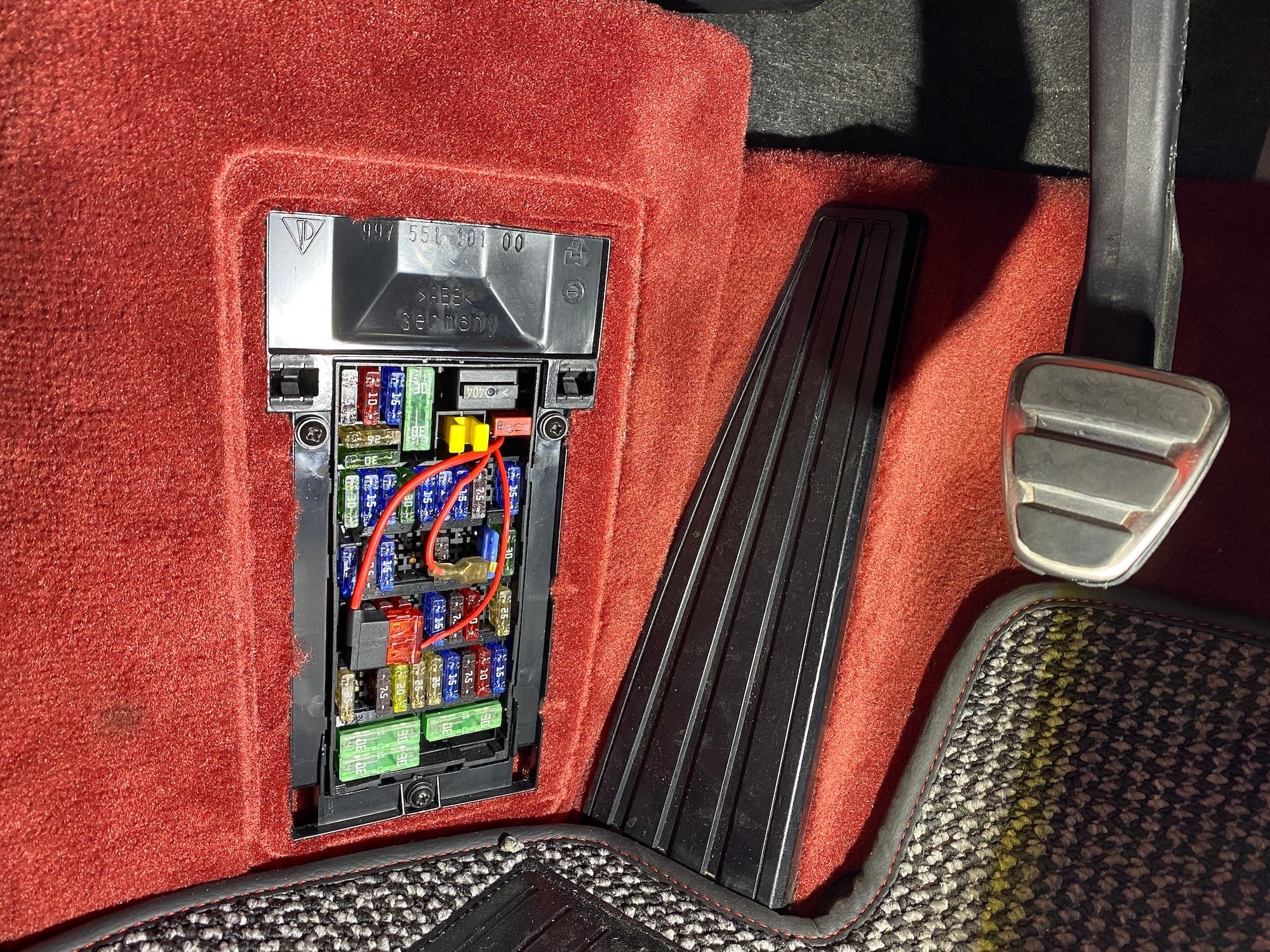
S3-C. Power lead wire installed at the C1 Fuse location. Note the orientation of the Fuse -- The Power lead wire exits at the BOTTOM.
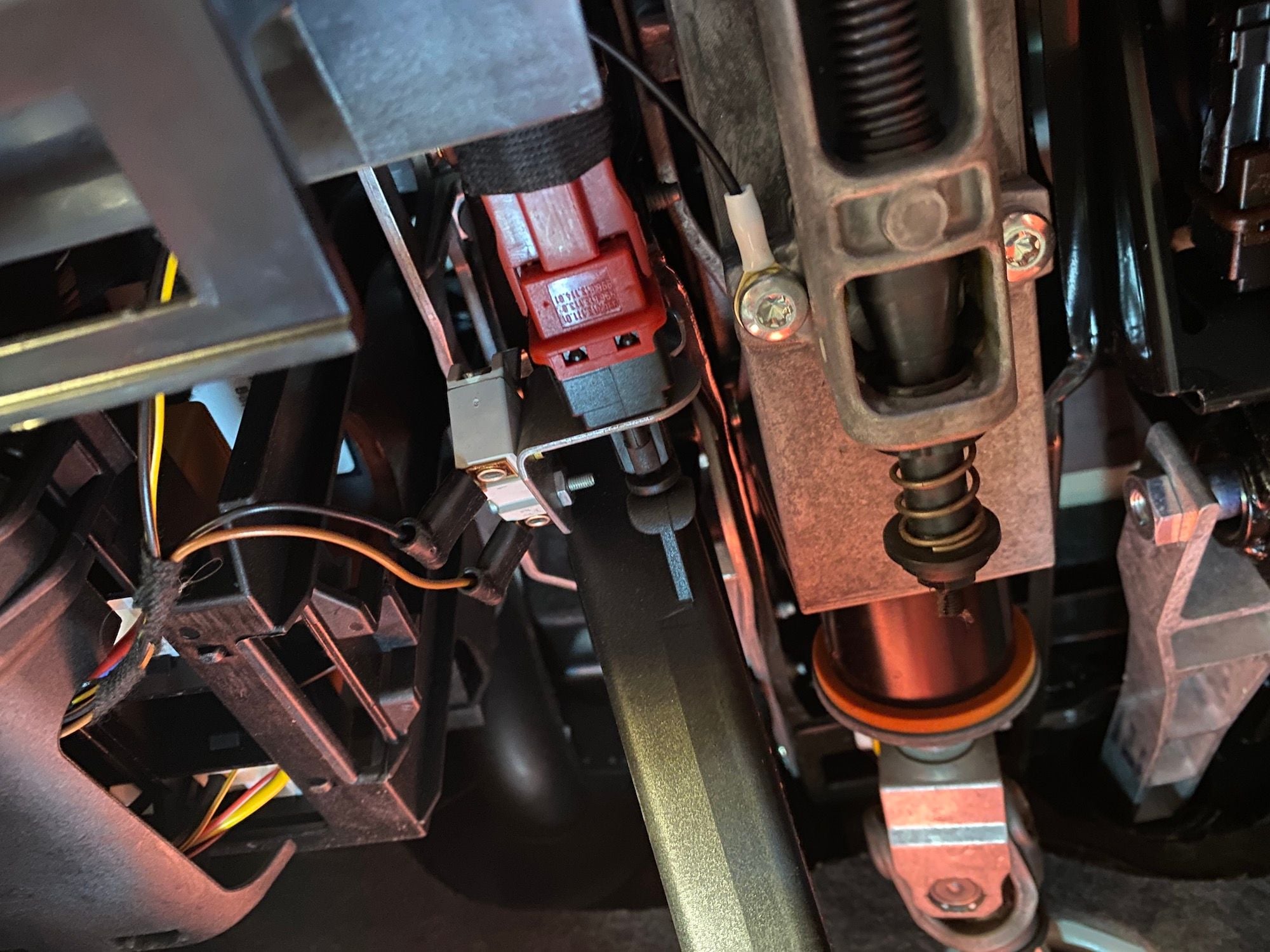
S4. Ground lead connection.
INSTALL PART FOUR — PSE CONTROL UNIT 1. Place the PSE Control unit and run all the wires to it. I secured it the the side wall forward of the door with the supplied double stick tape. It was a nice flat area. I oriented the control box so the connectors would be easy to pull off if needed — facing up. If I was worried about water, I would have flipped the orientation downward. 2. Connect the Blue/Gray control unit connector — CN2 — into the control unit. Note the orientation and location in the circuit diagram drawing. 3. Run the Green/Purple wires from the rocker panel to the control unit and then cut to fit — with some extra length (4-6 inches is good). Cut the Flexo sleeve about 2-3 inches shorter than the wire length and secure the end with heat shrink tubing. Make the pin connections on this end. The pin connector you want to use is the E-2 (shorter pin). Strip the wires — just a little bit — using the 20AWG stripper. Position the E-2 pin connector onto the wire making sure the bare wire is located at the middle crimp location and that the covered part of the wire is located at the end crimp location. Use the PA-20/21/09 crimper at the 1.9 position. Follow the orientation and directions on the package that came with the crimper. The crimp arms that will secure around the wire should be facing UP as you crimp down to secure the connection. After making the middle crimp, move to the end location and using the 1.9 position, crimp the connector to the covered wire. Repeat for both wires. 4. Look at the pin connector and notice the side that has a lifted metal flap. This is the side that will be visible when in the control unit connector — CN1. You just need to slide the pin connector into the correct slot of the CN1 control unit connector until you hear it lock in. Do this for both wires. Make sure the right color is in the right location. The order is RED, BLACK, PURPLE, GREEN. 5. Connect this Red/Black/Purple/Gray CN1 control unit connector into the control unit. Note the orientation and location in the circuit diagram drawing. 6. You are done with the install! But don’t close up your work until you test everything. 7. Test power to the PSE control unit. Put the key in the ignition and turn to the on position. The green light on the control unit should light up (indicating that there is power to the control box), if there is not light check your connections for the Power and/or Ground. 8. Test the PSE On/Off button. Start the car. The PSE orange light should be off on the switch. Push the PSE On/Off button, the the orange light should turn on as before. The exhaust should now sound louder. Turn the car off. 9. To set the PSE On/Off button in the ALWAYS-ON state, push the Blue button on the control box. 10. Start the car. You will note that the orange light of the PSE On/Off button will flash rapidly then stay on, and the exhaust will sound louder. Push the PSE On/Off button again and the orange light will go out and the exhaust will be quieter. Turn the car off, and then start again — the orange light of the PSE On/Off button will flash rapidly then stay on, and the exhaust will sound louder. Success! 11. Reinstall the carpet panel surrounding the Fuse panel and the Fuse panel cover. Just the reverse of Steps 1-2 in INSTALL PART THREE — FUSE BOX.
S1. PSE Control unit positioned in place. Test fit of the wiring.
S6. Everything all connected! I am using the ATC add-a-circuit fuse holder as I have another device using the same circuit.
Now that you see how it works, here is my installation write-up for the PSE Always On control unit kit. My installation is for a 987.2 Boxster Spyder. In an earlier post @Soaristo has provided a link to his website showing the install procedure on a 997.2. There will be some repetition, and I plan to go into greater detail on the install process so that if this is the first project you do, that you don�t need to go to other threads to find the information.
What a skillful DIYer you are!!
Thank you very much for describing the detailed installation method. I am deeply grateful.
I'm really glad that you became the first test driver.
Porsche owners are some of the most ****-retentive car enthusiasts out there (including me!). I can appreciate the effort, engineering, and enthusiasm for this solution. I agree that this functionality should have come with the car from the factory, defaulting to Sport mode and requiring the driver to disable when needed/desired. It's a sports car!! I like my solution even better. I just unplug the solenoid in the engine bay and have PSE on at all times. Woot!! Happy driving, my peeps.
Originally Posted by Liste-Renn
Wow.
All that time, intellect, effort, engineering and international communication to save one the hassle of pressing a button.
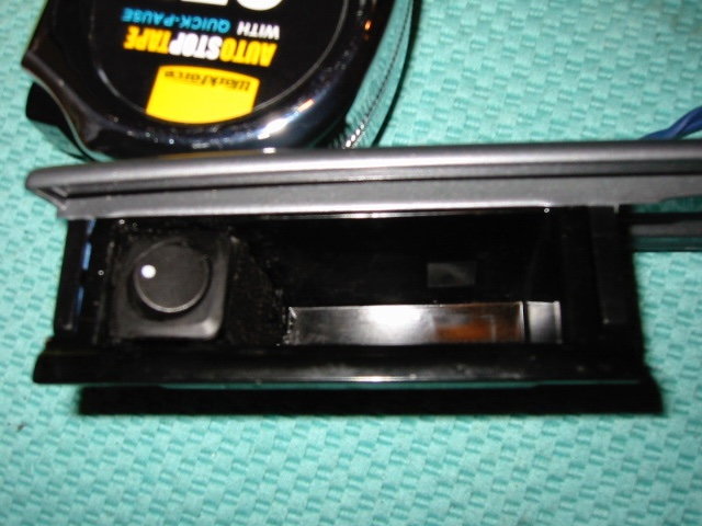
I found when I had PSE installed, that a simple on/off switch in the ash tray works fine for me, wired directly to the fuse box and solenoid.
had it on my 06S and my 09S. Sorry, obviously not for purists!
Yeah, Zach, I read the entire thread.
Pray tell, what does the mod do in addition to defaulting the PSE to the ON position?
A couple things:
1) Memory function - saves setting when car is turned off and defaults to that next time - not just a hard default to 'ON'
2) DME Override function - from the factory, the DME will close the PSE valves between 20-50mph, even when the valve is 'ON' aka loud. This is disabled.
Normally people will completely disconnect the PSE for the override function, rendering it inoperable. This device is worth it just for that IMO. The memory function is a plus.

 12-04-2020, 08:34 AM