When you click on links to various merchants on this site and make a purchase, this can result in this site earning a commission. Affiliate programs and affiliations include, but are not limited to, the eBay Partner Network.
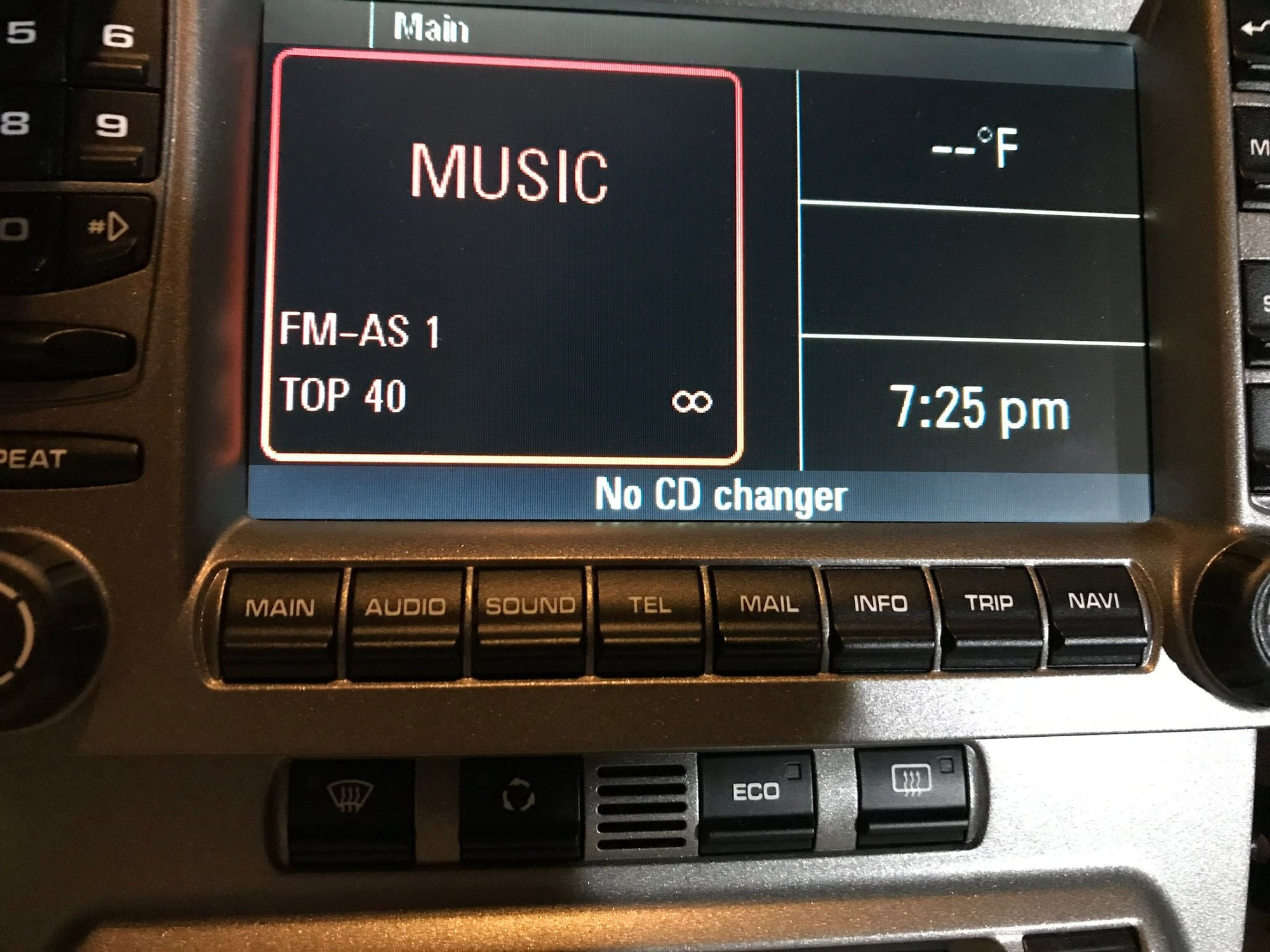
Ok...went to the shop to turn on the cd changer in the PCM. Unit still has no power. When I came home hooked the power cable and fiber optic...nothing. Question...I noticed on the display it still says no cd changer. 1. Does this mean they didn’t turn it on? 2. Or...Does this mean since the Bluetooth adapter isn’t getting power that it isn’t being recognized in the loop thus producing the message? Getting frustrated...��
Looks like they didn't turn it on. Mine goes to the single cd or if pushed again, goes to the LA Power. Does the fiber cable light up? It should emit light from one end of the cable.
That message means the PCM is looking for the CD (which the Lapower unit emulates) and not finding it, so that at least tells you the CD changer option is turned on in the PCM. It really sounds to me like the MOST ring is not connected correctly. The MOST ring is directional, do you have the FO cable coming from the PCM to the input port on the Lapower and the output of the Lapower to the input of the PCM? And you have verified power at the connector plug of the Lapower unit?
That message means the PCM is looking for the CD (which the Lapower unit emulates) and not finding it, so that at least tells you the CD changer option is turned on in the PCM. It really sounds to me like the MOST ring is not connected correctly. The MOST ring is directional, do you have the FO cable coming from the PCM to the input port on the Lapower and the output of the Lapower to the input of the PCM? And you have verified power at the connector plug of the Lapower unit?
Jeffblak, I followed the install instructions posted by Zettinger early in the thread along with a YouTube video from Enfig Car Stereo. Both instructions are the same. However, since I don’t have the Bose Amp or Installed CD Player I am curious if these are correct. My question is regarding step 3 and step 6 which I followed. For reference when he refers to DOWN arrow, this is the arrow pointing from the connector plug to the device it is plugged into (input). The UP arrow points from the connector plug to the wire exiting the device (output). Connecting it as below it appears I am trying to include a 3rd device in the loop. Today I wired straight from the PCM to the Bluetooth unit. This is looping only the PCM and Bluetooth unit. Doing it this way was the first time I could see light from the cable going into the Bluetooth unit and light on the cable going into the PCM. However, no power lights. Power cable has power as verified by my volt meter. So going with the wiring today means I am not using either of the 2 fiber optic cables that were originally plugged into the PCM. They are left unplugged behind the PCM. Does the latest wiring sound correct? Seller is sending me a new unit.
Zettinger’s install instructions from earlier in the thread.
3. remove the fiber strand with arrow DOWN from PCM connector.
4. open the outer fiber connector on one side of the LP1604 provided fiber optic cable, use the small flat screw driver and get the small blue lock out between the fiber cables.
5. remove one side of the connector completely on LP1604 provided cable
6. connect the removed DOWN arrow fiber strand cable from PCM plug to LP1604 DOWN strand with provided connector. (same connector as used for CD loop)
7. use the LP1604 fiber optic cable with UP arrow and connect it to the PCM plug.
6. press the small blue lock back in place on PCM inner fiber connector and re plug it in outer connector
7. route the LP1604 cable through the bracket behind the PCM to the passenger foot well.
Jeffblak, I followed the install instructions posted by Zettinger early in the thread along with a YouTube video from Enfig Car Stereo. Both instructions are the same. However, since I don�t have the Bose Amp or Installed CD Player I am curious if these are correct. My question is regarding step 3 and step 6 which I followed. For reference when he refers to DOWN arrow, this is the arrow pointing from the connector plug to the device it is plugged into (input). The UP arrow points from the connector plug to the wire exiting the device (output). Connecting it as below it appears I am trying to include a 3rd device in the loop. Today I wired straight from the PCM to the Bluetooth unit. This is looping only the PCM and Bluetooth unit. Doing it this way was the first time I could see light from the cable going into the Bluetooth unit and light on the cable going into the PCM. However, no power lights. Power cable has power as verified by my volt meter. So going with the wiring today means I am not using either of the 2 fiber optic cables that were originally plugged into the PCM. They are left unplugged behind the PCM. Does the latest wiring sound correct? Seller is sending me a new unit.
Zettinger�s install instructions from earlier in the thread.
3. remove the fiber strand with arrow DOWN from PCM connector.
4. open the outer fiber connector on one side of the LP1604 provided fiber optic cable, use the small flat screw driver and get the small blue lock out between the fiber cables.
5. remove one side of the connector completely on LP1604 provided cable
6. connect the removed DOWN arrow fiber strand cable from PCM plug to LP1604 DOWN strand with provided connector. (same connector as used for CD loop)
7. use the LP1604 fiber optic cable with UP arrow and connect it to the PCM plug.
6. press the small blue lock back in place on PCM inner fiber connector and re plug it in outer connector
7. route the LP1604 cable through the bracket behind the PCM to the passenger foot well.
Based on the shop manual, the four possible factory devices that are connected to the MOST ring are the factory phone, the Bose amp, the Nav unit and the CD changer. If you don�t have any of those then I�m not sure if there is anything on the ring or if the loop is even made continuous by the factory. Each MOST connector has two arrows on it. One points into the unit the connector is plugged into, and one faces away. As you would expect, the in arrow is the input to that unit and away arrow is the output to the remote or next unit. The factory cables have directional arrows printed on them but the ones supplied with the new unit don�t. So mark the cables in some way at each end so you don�t get them crossed. Connect the out from the PCM to the in of the Lapower, and the out from the Lapower back to the in to the PCM.
You stated that you don�t have the CD changer or the Bose amp, if you don�t have the factory phone module or Nav either you may not even need the factory MOST cable connected, but I�m not sure about that. It may connect to something not shown in the shop manual. Try it with just the Lapowrr cable plugged directly into the PCM at least until you get it working. If there are no other problems and nothing else is disabled then you can leave the factory MOST cable out of the loop. I suspect you not were seeing light from the factory cable ends because the loop was not completed by the factory since you had no optional devices to connect. Good luck.
Thanks for the info. Very helpful. I am waiting on the new unit to rule out that mine is defective. I am leaving it wired how I left it...directly from the PCM to the LA Power unit. I will report back.
Thanks for the info. Very helpful. I am waiting on the new unit to rule out that mine is defective. I am leaving it wired how I left it...directly from the PCM to the LA Power unit. I will report back.
Regards
It sounds your PCM doesn't have any peripherals on the MOST ring.
My guess would be that you can plug in the LaPower included fiber cable directly to the PCM and LaPower unit.
However I assume you need to have your PCM programmed for CD-changer option.
csmab,
After following a few of these threads it seems like the 2007 and newer cars (without factory CD changer) have had success without PCM program changes, Your car is a 2006 and I believe I have seen other 2006 and older car owners also stating they needed the CD changer turned on. I do know that the Lapower unit powers down when there is no signal on the MOST ring even when connected to constant power. You could also have a bad BT unit so start with the PCM program change and then if that does not do it exchange your Lapower unit. Once working I think you will be very satisfied with it. It actually works very well, even for a unit 3x the price.
Originally Posted by csmab
Jeffblak - that is a good point regarding 2006 vs 2007 997's. I didn't pay attention to model years while reading through this thread.
My 05 does not have a CD changer yet the Lapower unit worked fine, no CD changer activation required.
Here a DYI from my experience with my stock 997.1 with Bose and CD changer.
Tools required:
- Philips screw driver
- small flat screw driver
- small pick
- T20 hex
- T30 hex
- 5.5 mm allen wrench
- 7 mm wrench
- Pliers
- knife
- tape or well crow for cable management
- paper clip (USB cable holder in glove compartment)
- beer
Timeline:
15 min front trunk work
15 min PCM and foot well panels removal
15 min Fiber optic Loop extension work
5 min power cabling to LaPower LP1604 unit and test function of fiber/power
5 min Microphone cable routing
5 min USB cable routing to glove box
10 min locating LP1604 in foot well
20 re-installing PCM, panels and cleanup
10 min test and connect, victory beer
100 min total project time.
Process: Front trunk work the CD changer fiber has to be looped in the 997. if this step was not done, the LP1604 will show connected phone and reception in display but no sound since PCM still detects the CD changer.
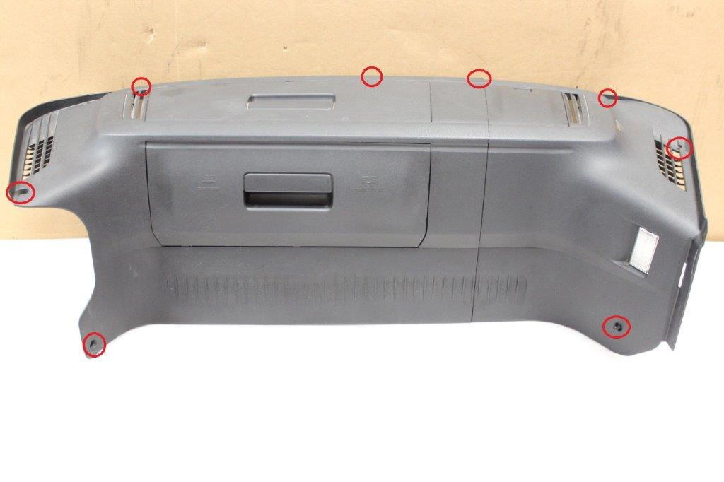
1. Open frunk and remove the rubber liner around the cover
2. locate the 8 Philips screws around the plastic cover Cover screw locations
3. Remove the three plastic covers and pull the whole cover to the side. Frunk light can be left in place since you will work on opposite side.
4. locate the fiber cable on the CD changer and unplug it with the little tab on the side.
5. use the small pick and get small white lock out between the fiber cables and remove the fiber strands from the connector
6. remove tape wrap around the fiber optic cable for a few inches to be able to loop the cables together.
7. use the provided fiber connector and connect both fiber strands together. and place secure next to CD changer. CD Changer fiber loop
8. reinstall the large cover with 8 screws, insert small covers liner and rubber seal
PCM and foot well panels removal PCM has to be removed in order to extend the fiber for the Lp1604 unit.
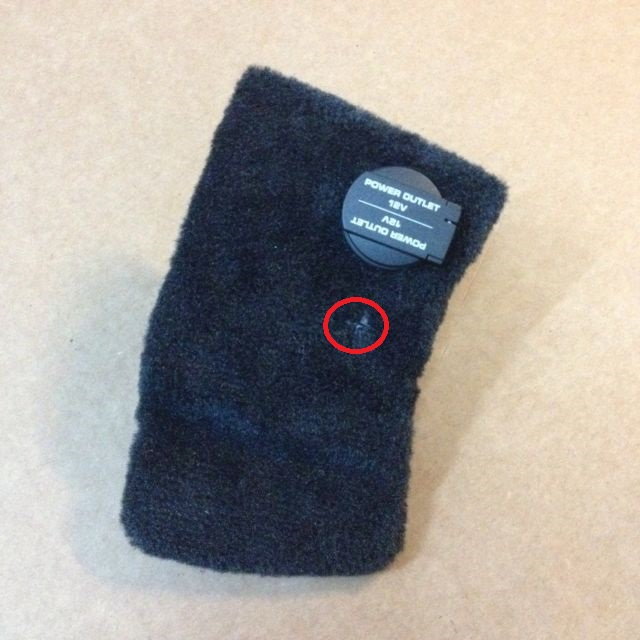
1. in passenger foot well, use the T30 hex and remove the single screw what holds the panel with the 12v power outlet, unplug the outlet. Screw location panel in foot well
2. remove the same panel on the driver side.
3. use T20 hex to remove two screws for the panel on passenger side and driver side. four screws combined.
4. Pull the panels off.
5. use 5.5 mm allen wrench and half turn the four screws holding the PCM in place.
6. use 7 mm wrench and lose the screw on the right side of the PCM for half an inch. (this holds the PCM and you wont be able to remove it with the screw in place)
7. remove PCM and unplug all cables
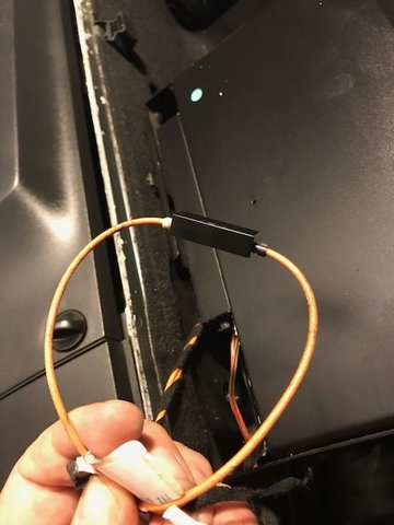
Fiber optic Loop extension work purpose is to extend the MOST fiber loop from Bose amplifier, CD changer and PCM. for the 997 we replace the CD changer and looped prior the fiber.
1. remove exiting fiber cable from cable manager behind PCM
2. open the outer fiber connector on PCM, use the small pick and get small blue lock out between the fiber cables.
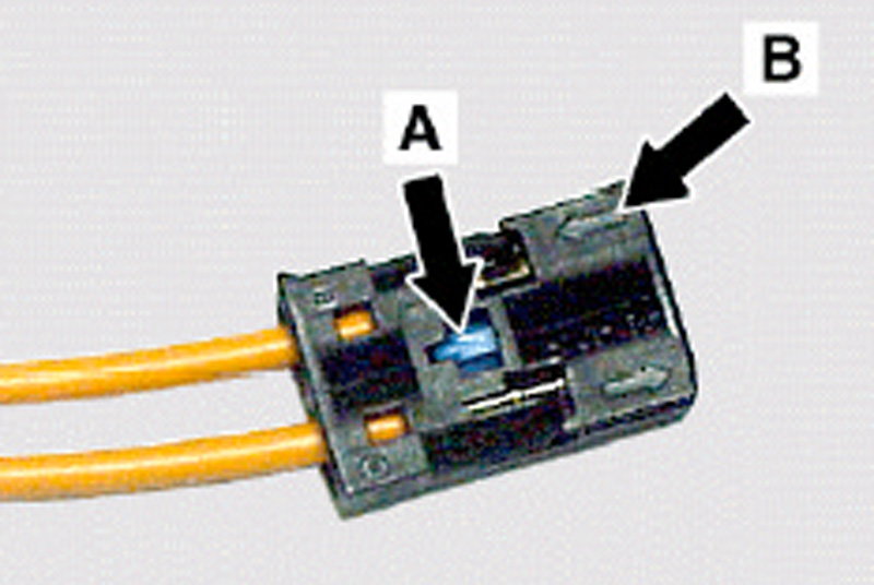
Example: Example:
A Blue secure lock
B UP arrow
3. remove the fiber strand with arrow DOWN from PCM connector.
4. open the outer fiber connector on one side of the LP1604 provided fiber optic cable, use the small flat screw driver and get the small blue lock out between the fiber cables.
5. remove one side of the connector completely on LP1604 provided cable
6. connect the removed DOWN arrow fiber strand cable from PCM plug to LP1604 DOWN strand with provided connector. (same connector as used for CD loop)
7. use the LP1604 fiber optic cable with UP arrow and connect it to the PCM plug.
6. press the small blue lock back in place on PCM inner fiber connector and re plug it in outer connector
7. route the LP1604 cable through the bracket behind the PCM to the passenger foot well.
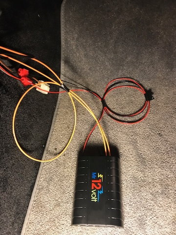
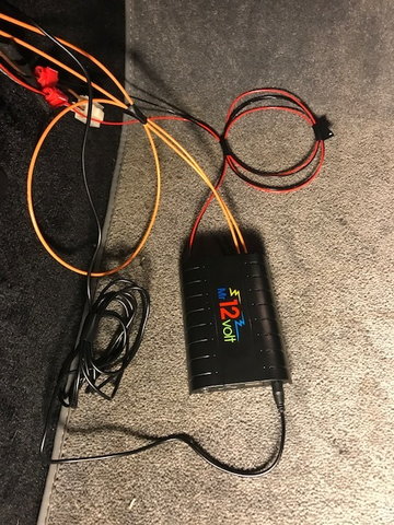
Power cabling to LaPower LP1604 unit and test function of fiber/power I used the 12v power outlet in passenger foot well as source for the LP1604.
1. the 12V power outlet has three cables, we focus on constant power and mass. locate red/black, 12v not switched, and the brown mass cable.
2. use the Lp1604 provided crimp and connect the red Lp1604 cable with the red/black cable from the outlet. use the pliers to press the connector all in.
3. use the Lp1604 provided crimp and connect the black Lp1604 cable with the brown cable from the outlet. use the pliers to press the connector all in.
4. re connect PCM cables and fiber cable, slide PCM in slot.
5. connect power and previous created fiber ring to LP1604.
6. press PCM for radio to start. If all work was done, the unit should fire up and blue LED indicator will light up. You will need to connect your phone Bluetooth to the device "Car Kit".
7. the PCM will show your phones name on the left and reception. Change on the PCM to CD changer and BT audio will appear.
Microphone cable routing I chose the location in the dash since it's hardly visible and should be the best location for function.
1. place Micro in position and route cable along the gauge cluster to the thinnest area in front of the steering wheel.
2. use small screw driver to tuck the cable in place. Microphone in position and cable routed
3. route cable around the trim and along the removed PCM side panel.
4. route cable to passenger side over driver side foot well.
5. plug in Aux cable connector to MIC port. MIC cable connected.
USB cable routing to glove box I routed the provided AUX cable and iPhone lightning cable to the glove box. I learned later that when AUX is plugged in, the BT audio is disabled and removed it again.
1. I used a small paper clip to secure cable in glove compartment.. removed one clip side.
2. route cable through the back of the glove box down to passenger foot well.
3. plug in to USB port in LP1604
Locating LP1604 in foot well I stored the fiber, power and Microphone cable in front of bracket while LP1604 between A/C and dash bracket.
1. coil up fiber, power and microphone cable and use tape or well crow to keep them managed.
2. tuck the cable behind the dash bracket
3. located the LP1604 unit behind the AC inside the bracket to be covered by the PCM cover panels.
4. test function again before proceed to next step.
Re-installing PCM, panels and cleanup The PCM was just left lose before, all panels need to be mounted back.
1. basically reverse the steps, use 5.5 allen wrench to lock PCM, 7mm wrench, plug in panels and secure with T20, foot well brackets with T30.
2. remove garbage and tools from foot well.
Test and connect, victory beer Go through functions, test call, plug in phone to charge. Do this process with an beer in your hand.
Zettinger, your instructions are invaluable. It is much clearer than the manual that came with the unit. Saved me a lot of time.
Thank you
Ugh! Replacement unit received today. Installed it and no power lights, same as the original. Power cable is getting power so this is not the issue. My system is the base with no cd changer or nav. Dealer programmed the PCM for a cd changer. Wiring is correct as the above instructions from Zettinger. I also tried wiring only from the PCM to the Bluetooth unit and back to the PCM creating a loop between the 2. In a base system I have no idea where the fiber optic wires go running out of the back of PCM since I don�t believe there is anything in the MOST loop on the base system. I could be wrong. Very frustrated. Already spent $75 at the dealer to program PCM. Not looking to throw more money at this since it was supposed to be a cheap plug and play. Open to ideas.
Ugh! Replacement unit received today. Installed it and no power lights, same as the original. Power cable is getting power so this is not the issue. My system is the base with no cd changer or nav. Dealer programmed the PCM for a cd changer. Wiring is correct as the above instructions from Zettinger. I also tried wiring only from the PCM to the Bluetooth unit and back to the PCM creating a loop between the 2. In a base system I have no idea where the fiber optic wires go running out of the back of unit since I don’t believe there is anything in the MOST loop on the base system. I could be wrong. Very frustrated. Already spent $75 at the dealer to program PCM. Not looking to throw more money at this since it was supposed to be a cheap plug and play. Open to ideas.
Thanks
Check my post above, someone had an similar problem. He had an CD changer to test the MOST ring and power from the battery direct.
If the fiber ring is not correct, the power will not light up.

 05-04-2018, 11:17 PM