When you click on links to various merchants on this site and make a purchase, this can result in this site earning a commission. Affiliate programs and affiliations include, but are not limited to, the eBay Partner Network.
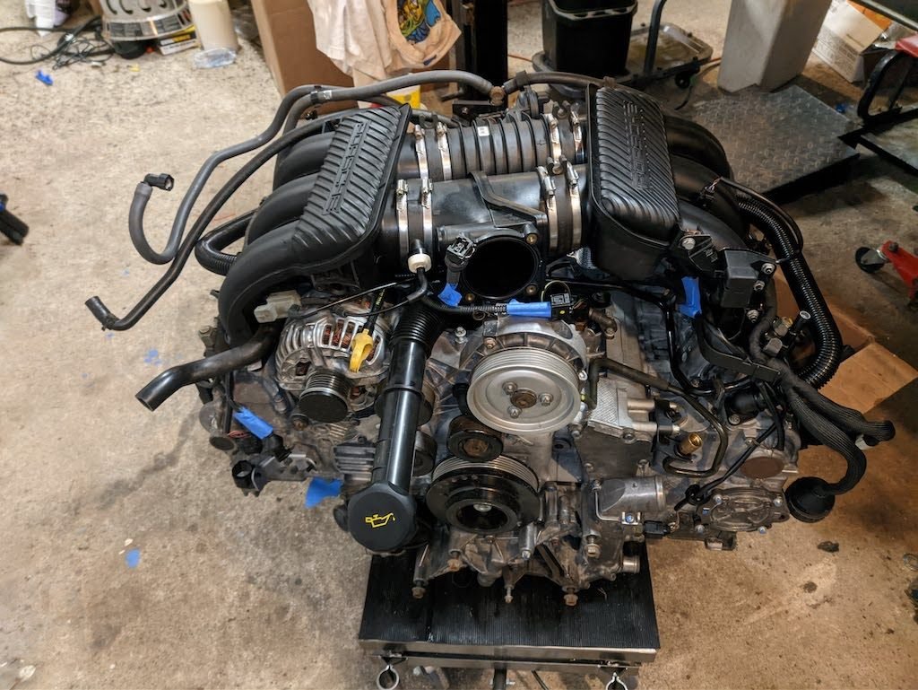
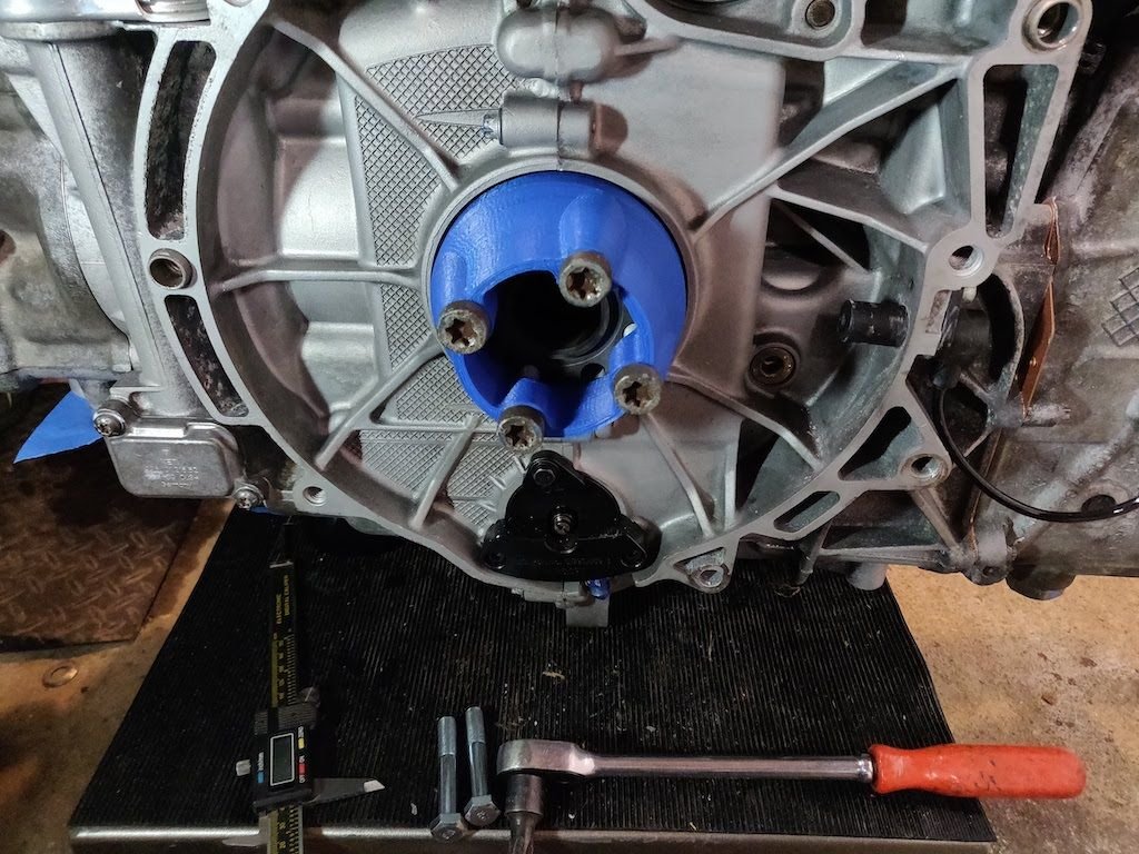
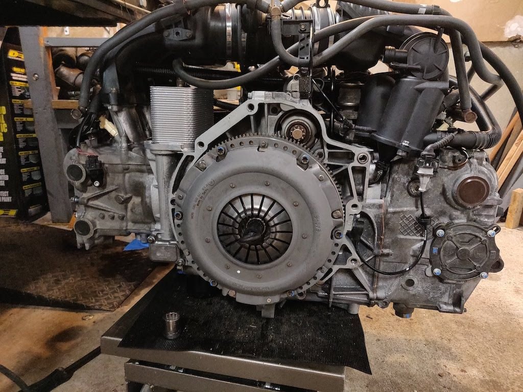
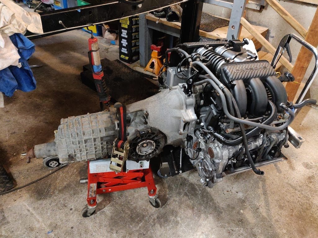
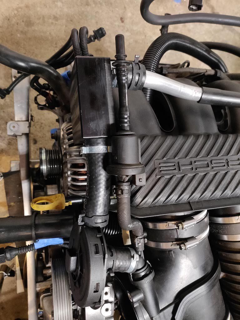
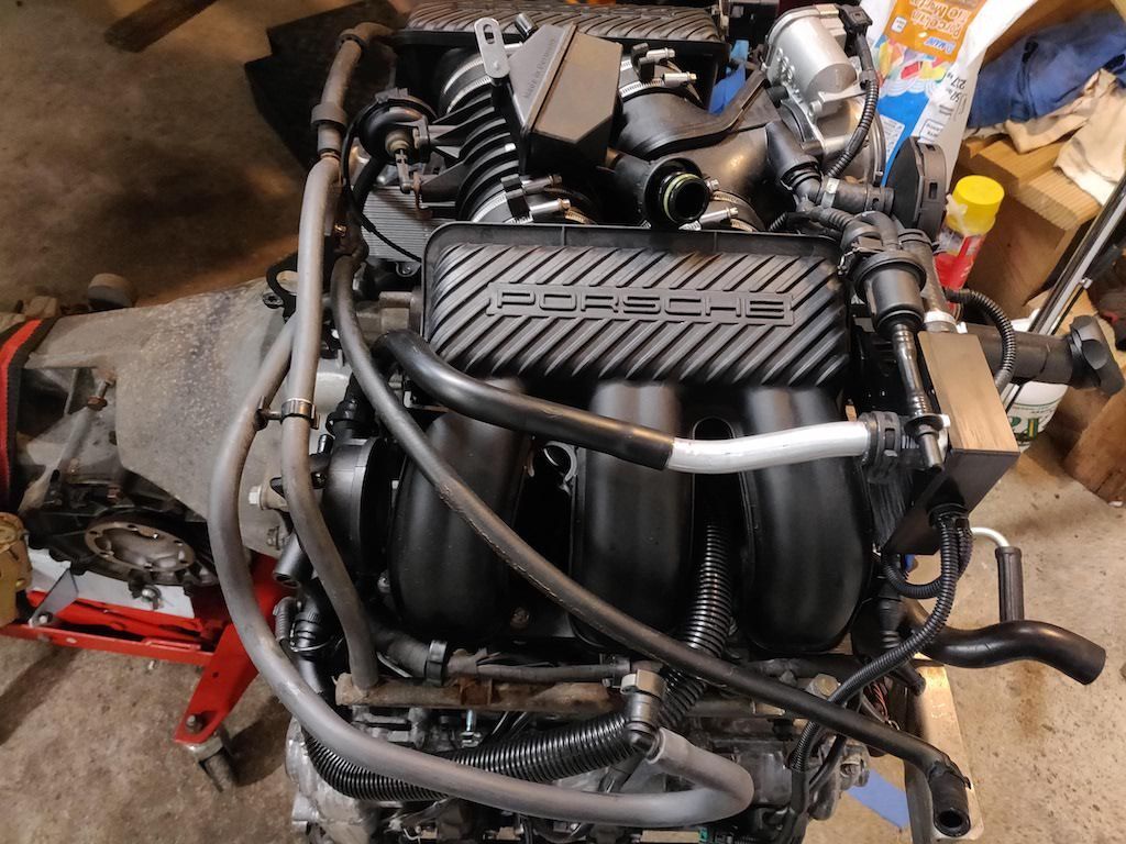
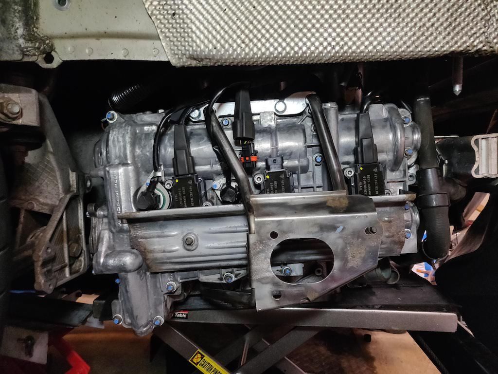
Weekly update. The intake manifold is installed as well as the RMS, flywheel and clutch. I broke one of the connectors on the tube for the U-AOS because it must have been too cold and the plastic was brittle. I should have the replacement tomorrow and I can then install the U-AOS. I will then install the transmission to the engine and hope to put it back in the car this Saturday. I don't think I will get the car to the point of starting this weekend. Just hoping to get the engine and transmission mounted.
I will need to pick up another propane tank for this Saturday because it's pretty cold up here in NJ.
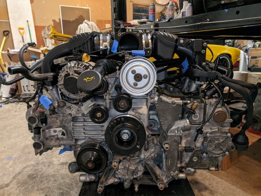
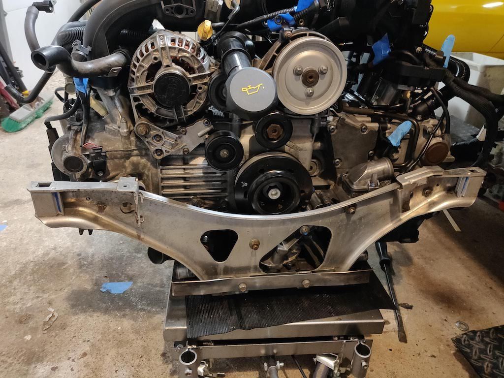
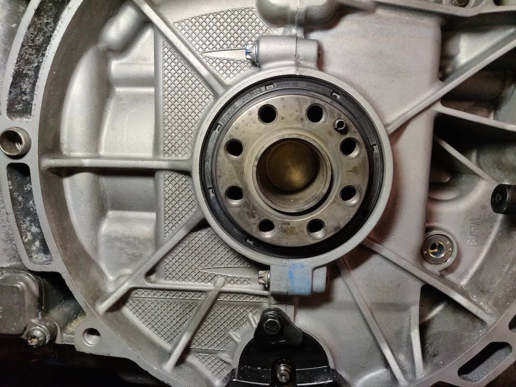
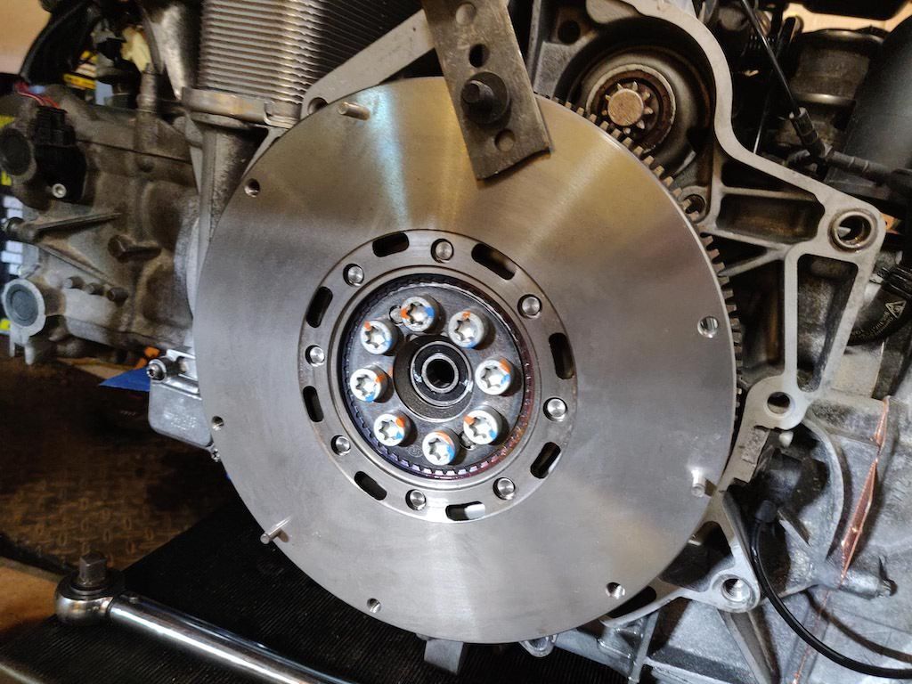
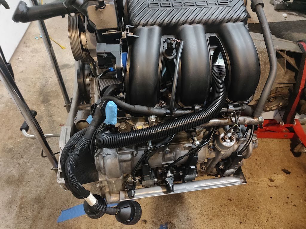
Intake installed Engine brace installed Back of the engine before installing RMS, flywheel and clutch Picture of the RMS tool I used to install the seal Seal installed to the 13mm depth Flywheel installed. Held in place using my homemade tool Clutch installed and waiting for the transmission.
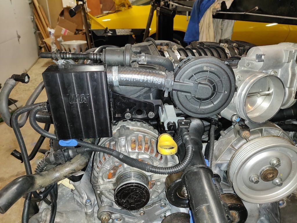
Good progress. I broke that plastic cross-over pipe when doing the UAOS so breaking some of this old plastic stuff is something to be prepared for. It's also nice having 2 less coolant lines running to the back of the engine and the AOS. Do you have a Durametric and a smoke machine just in case some gremlins pop up once the engine is running?
Good progress. I broke that plastic cross-over pipe when doing the UAOS so breaking some of this old plastic stuff is something to be prepared for. It's also nice having 2 less coolant lines running to the back of the engine and the AOS. Do you have a Durametric and a smoke machine just in case some gremlins pop up once the engine is running?
I do like not having the coolant lines going to the AOS.
I have a Durametric and saw instructions on how to build a smoke machine if there are issues with vacuum leaks. I also have a coolant fill tool to check for leaks in the coolant system.
amargari: Wow! What an impressive job on this engine rebuild. Pardon the interruption, and I hope it is not out of line to ask if you can help me solve a cam timing problem since you were just at that point a few weeks ago.
I'm not super familiar with the cams and chain guides, etc, on my 2002 3-chain M96, but I did a lot of reading, including the 996 shop manual online. All I needed to replace were the tensioners and the chain guides. All went well on bank 2, and the timing was perfect. Rotated the crank 360 degrees, smooth and easy, and locked the #1 cylinder at TDC on overlap stroke. Once I replaced all of the chain guides and tensioners on bank 1, I installed a new intake cam bolt in the required two stages. When I was angle torquing the bolt to the 110 additional degrees, the aluminum cam holding tool (yes, I chose poorly) bent under pressure from the bolt torque. That in turn rotated the cam backwards. I did not notice this. And I had a steel Allen wrench in the TDC hole on the crank pulley. Still not sure how the crankshaft moved with that key in the hole, as it did not bend. When I removed the wrench and rotated the crank about 10-15 degrees I heard a pop and saw that I was just coming back to TDC! Now the engine is stuck. So, today I removed both cams again to let the valves close in case a valve was out of time and contacting a piston. No luck -- the engine is still stuck for normal rotation, but it does rotate backwards a few degrees (I know... never do this, but I had to determine if a piston was obstructed on the way up). Could I have broken a valve spring and it is now laying on a piston? Any thoughts before I remove the bank 1 head? Thanks very much for any advise to help me correct this mess I have made.
I'm not an expert on the M96 engine so I would only be guessing here. But here are a few of my thoughts.
It isn't a valve spring in the cylinder as they are on the top of the head and can not fall into the cylinder. If a spring is broken, you would see it once you took the cams out.
If the cam spun without the crank spinning, then any of the following could have happened:
A chain broke. Seems unlikely as they are pretty stout
A chain sprocket on the IMS spun. This has been known to happen and that's why people weld or pin them to the IMS.
The cams broke where the sprocket attaches to the cam.
What cam holding tool broke? Is it the one that slides into the back of the cams or is it the two piece tool that connects to the front of the intake cam.
Quick update. My AOS tube delivery has been delayed by the Post Office, so I am not able to install the engine and trans this weekend. Hopefully, later this week.
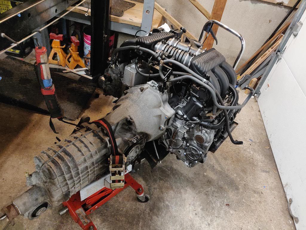
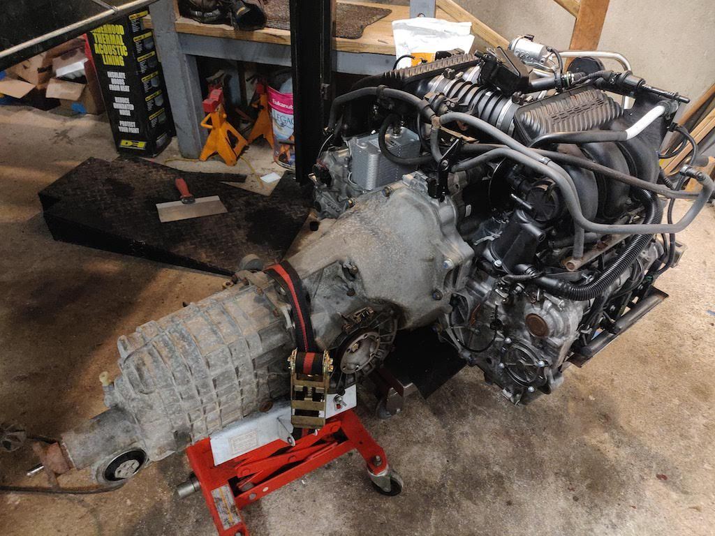
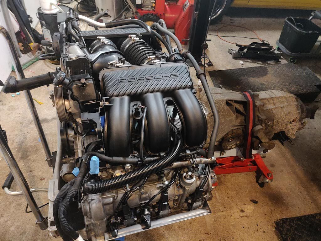
I was able to mount the transmission to the engine with only one issue. Somehow I lost one of the transmission bolts. I lost the M12-1.50 x 50mm bolt. Of course that bolt is $18.00 where the other bolts for the transmission are around $6.00. I will try and find a flange bolt of that size or go to the dealer and order one. It's not a rush as I can install the engine and trans without this bolt and install it later.
One more thing I did was to install the Function-F1rst shifter cable ends. They are finally available for the 996 and wanted to give them a try. Overall they are well built and should improve the shifter feel.
Here are pictures of the progress.
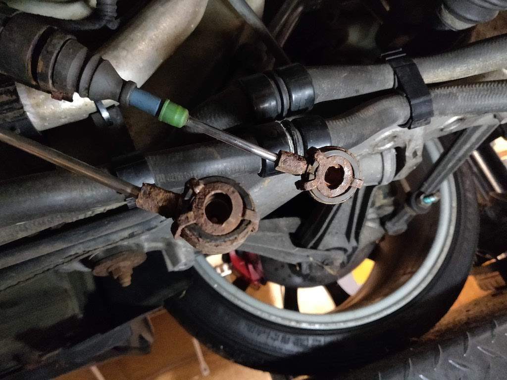
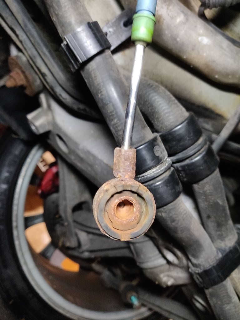
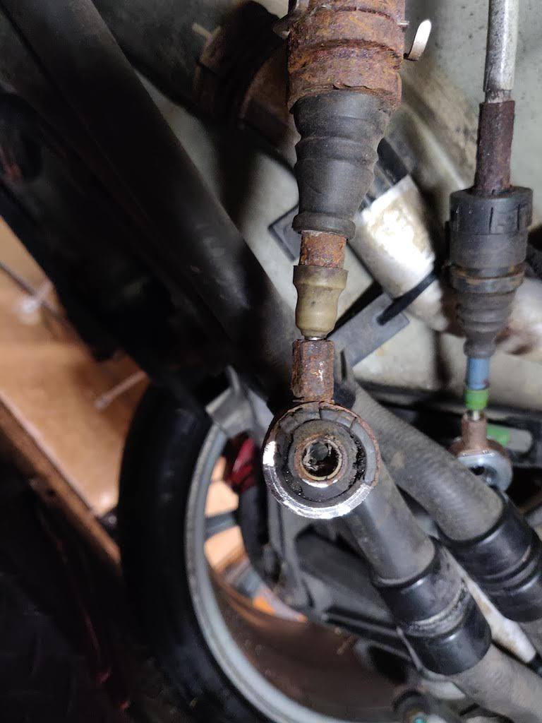
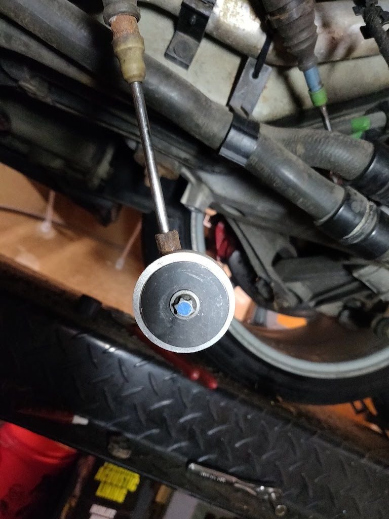
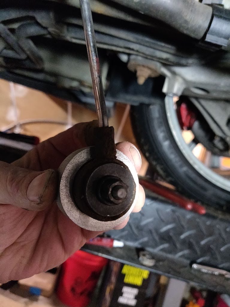
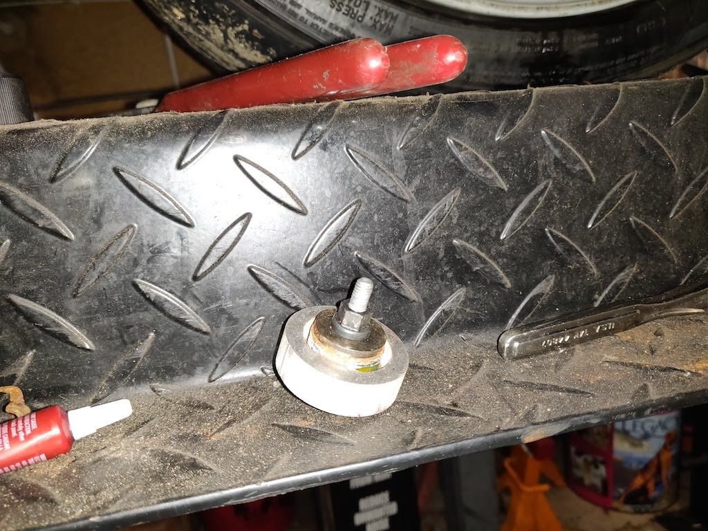
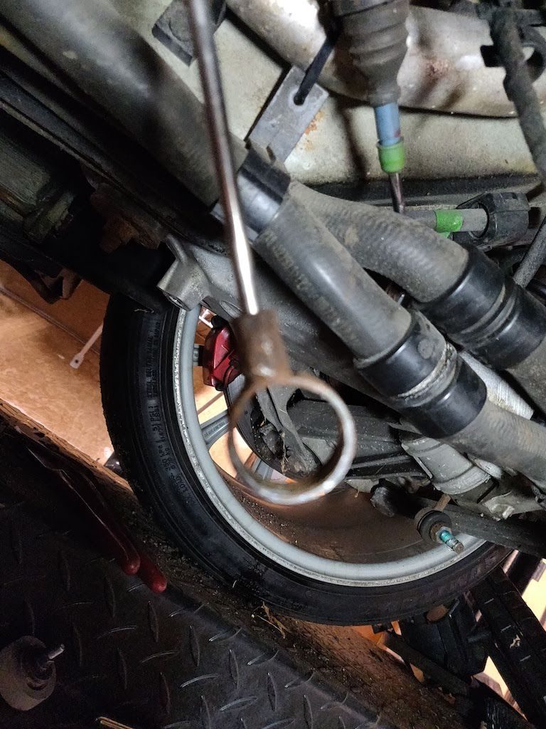
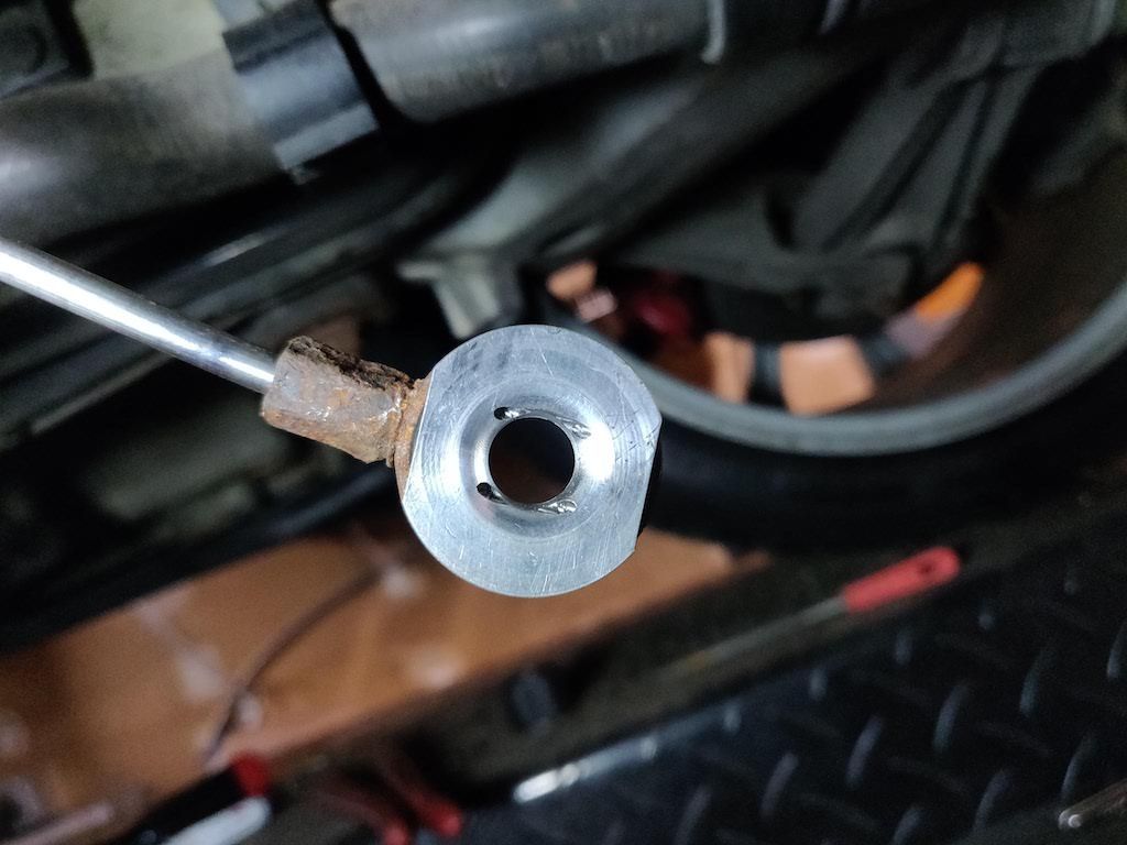
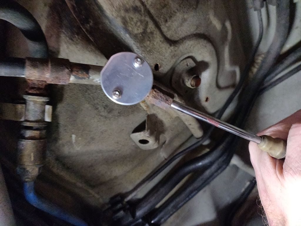
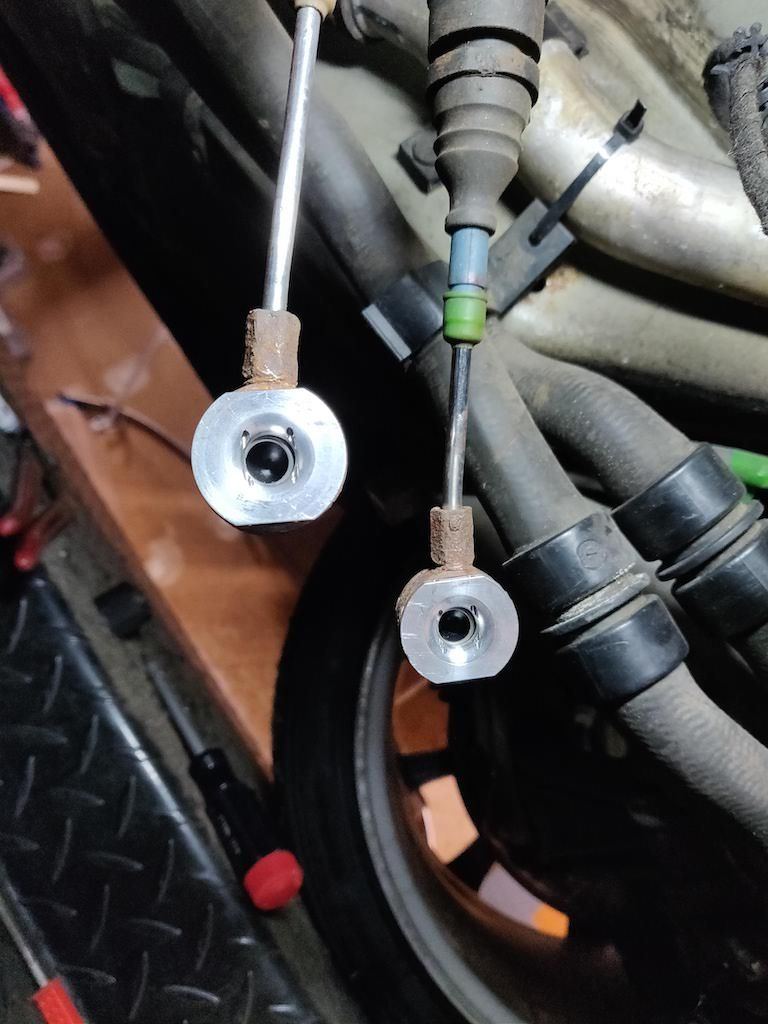
Here is the engine with transmission installed. This is the Function-F1rst kit. It comes with everything you need including the installation tool. Here are my original cables. They are rusty with worn bushings. Here is the bushing with the 3-pronged oval clamp removed Next step is to drill a 1/4 hole through the center of the bushing and grind away some of the bushing lip. This is the tool used to pull the bushing out. This is the second one I did and wound up messing up the screw that comes with the kit. I had a spare throttle body screw and it was the perfect size. Here is the back of the cable. It has a washer that presses against the bushing as you tighten the screw. Here is the tool with the removed bushing. Here is the cable without the bushing. Here is the bushing installed. I used a large set of channel lock pliers to press the bushing in. I used the big washer from the tool to protect the busing face. There is a Delrin bushing and circlip that gets installed. Here is the back of the bushing installed. The screws use lock washers, but I added a dab of thread locker to make sure they stay. Here are my finished cables.
A quick update on the missing bolt. It looks like I am missing a M12-1.50 x 70mm bolt not a 50mm bolt. The Bentley book lists the bolt as a 50mm but the parts diagram for the 996 and 997 lists the bolt as a 70mm. I went and checked the depth of the hole and the 70mm bolt is the correct bolt. In fact I was able to thread a 70mm bolt in the hole by hand without a ratchet. So at least I will be paying half as much for the bolt now. A small victory, but still a victory LOL.
Thanks amargari. I guess I typed too fast and put two subjects in one sentence. I was thinking that a valve dropped, not a spring. Now, after removing the cams and each lifter one at a time, the valve ends are all in the same spot relative to the clip that holds them in place. So I hope that rules out a valve issue. I must have felt a chain pop over a sprocket, but I don't know which one. Bank one chain is not broken, and I can look at the IMS sprocket and it doesn't look unusual. I can only see a small part of it since the case and chain guides are restricting my view. The last shop that pulled the bank 1 valve cover really did a bad job putting it back on. I found a misaligned cam bearing screw that crushed a sleeve insert, which caused the cam bearing clamp to be installed at a slight angle. Then they did not bother to place the sprocket bearing sleeve on its hidden post, so the bearing screws just pressed the aluminum sleeve into the face near the factory hole, creating a new "hole" and also causing more binding as the cam rotated in the sleeve. So, if the intake cam was slowed or even stuck in place I can understand why the chain jumped a tooth. But now that the cams are out, I can't figure out why the crank won't turn clockwise.
Full discIosure here, now that you know I'm a first timer on this project. I had to remove the oil pump housing to get to the bank 2 chain guide bolt. I was having trouble getting the oil pump housing back on since the IMS shaft was pushed over to one side. So, I thought that turning the crank would relieve pressure on the back chain and also show me that the cam timing was correct. I saw the IMS end move a bit as I began to turn the crank when I heard the pop. I wonder if perhaps the IMS jumped or slid sideways and got into a bind. Now I'm afraid I'll have to split the case open to inspect that chain. In any event the crank is stuck and I don't know how to do any other testing. I suppose both heads will have to come off, then case splitting if I don't see a cause for the jam.
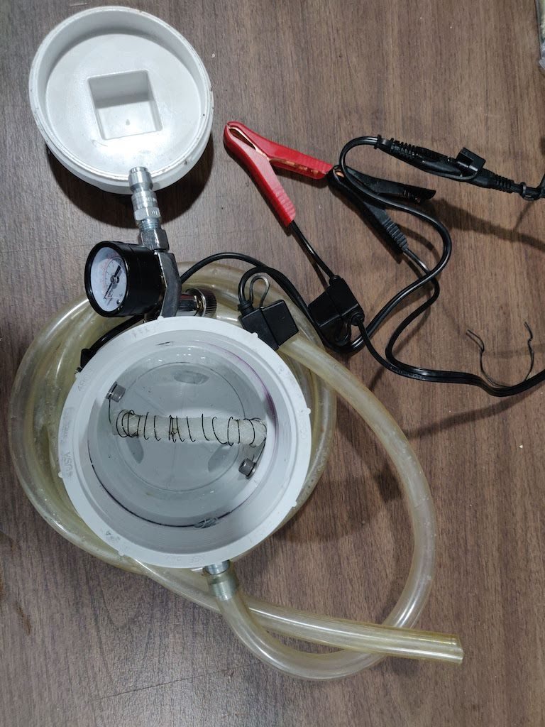
@amargari since you're waiting for the AOS to arrive now is a good time to build your smoke device and check for vacuum leaks, I think.
Way easier to spot and remedy them now (should there be any) than when the engine is back in the car.
I'd plug the AOS-related holes and go for it. Fixing any leaks now won't slow you down later on and once the new AOS has been fitted it's quick and easy to hook up the smoke device again and check the AOS install.
And thanks for the write-up and pictures of the FF cable end install! Lots of insight given by them.
Last edited by hardtailer; 01-30-2022 at 04:48 AM.
@hardtailer , I started on building the smoke machine today. I am only waiting on Amazon to deliver the resistance wire. The rest is ready to go.
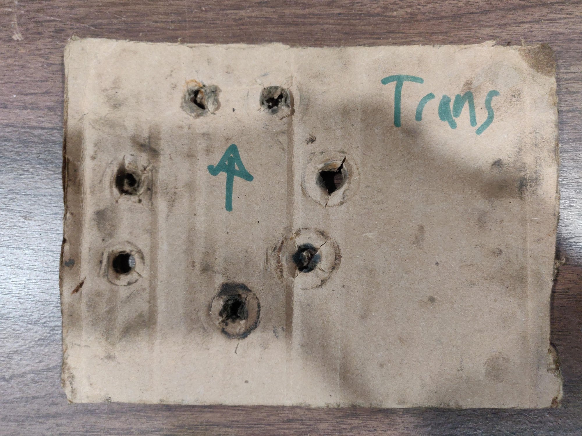
One last item on the missing transmission bolt. I looked on the piece of cardboard I used to store the bolts on. I used the cardboard to make sure the bolts went back where they belonged. There were only 7 holes in the cardboard. So, some time before I got the car, one of the transmission bolts was lost or never installed from the factory. I feel much better that I am not going crazy.
Edit: If you look at the first picture when I started this thread a few months ago, you will notice that the top transmission bolt is missing.
Only 7 holes in this cardboard and there are supposed to be 8 transmission bolts.
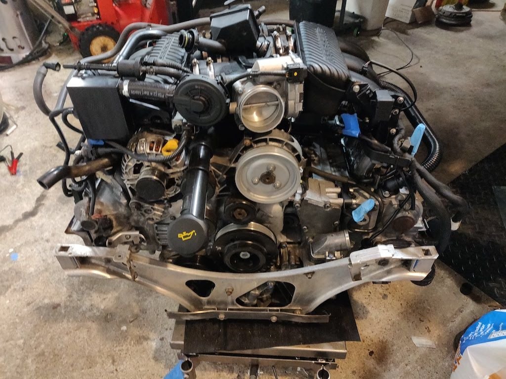
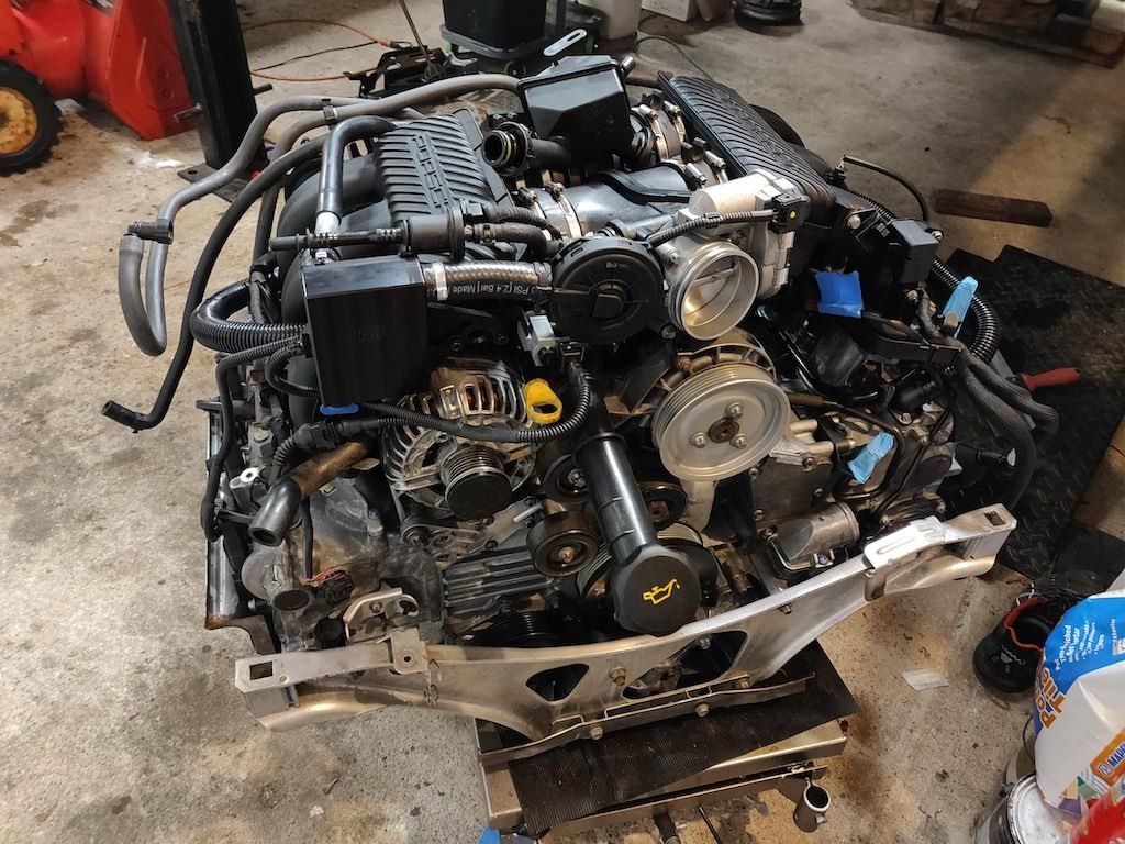
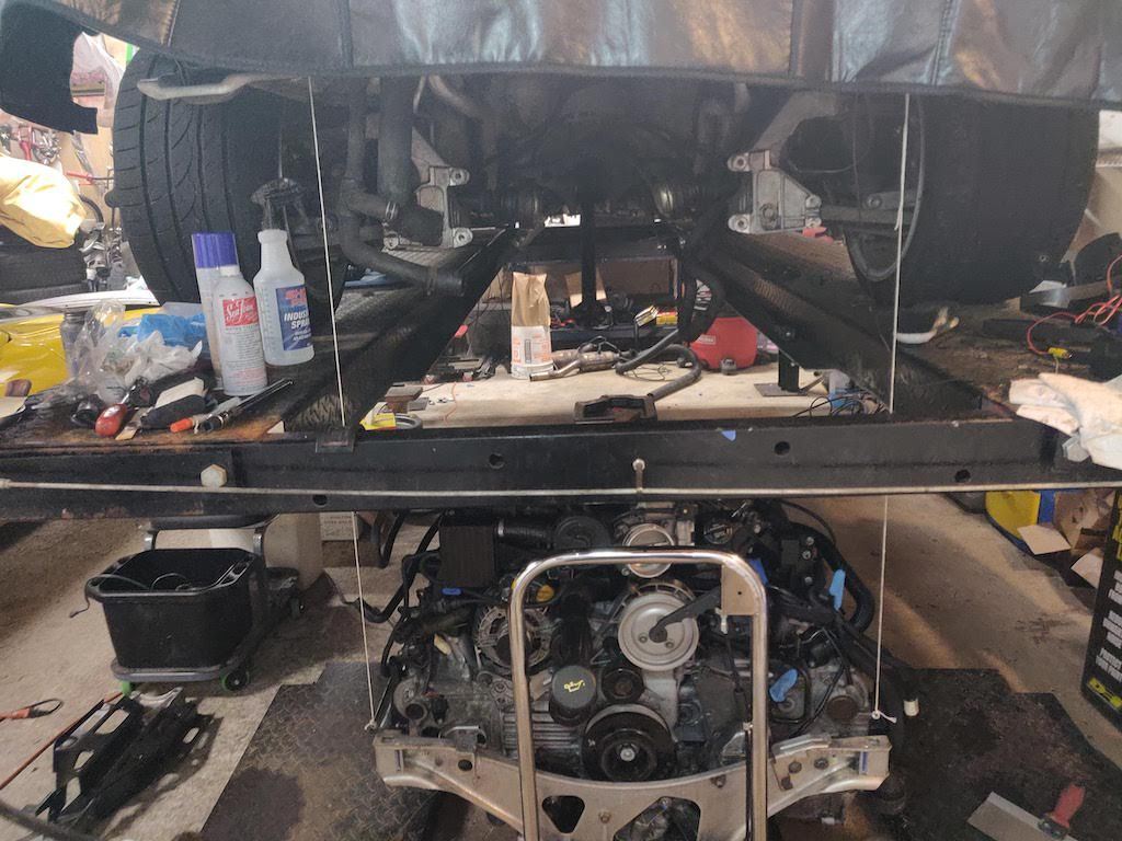
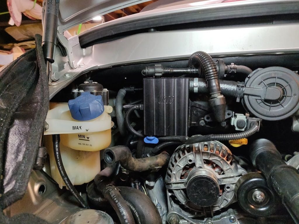
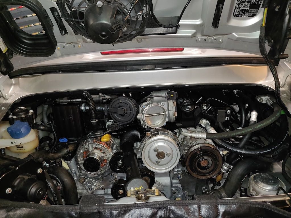
The engine is physically installed!! I still need to put final torque on all the mounting bolts but it is in.
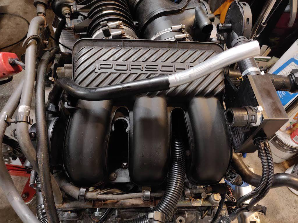
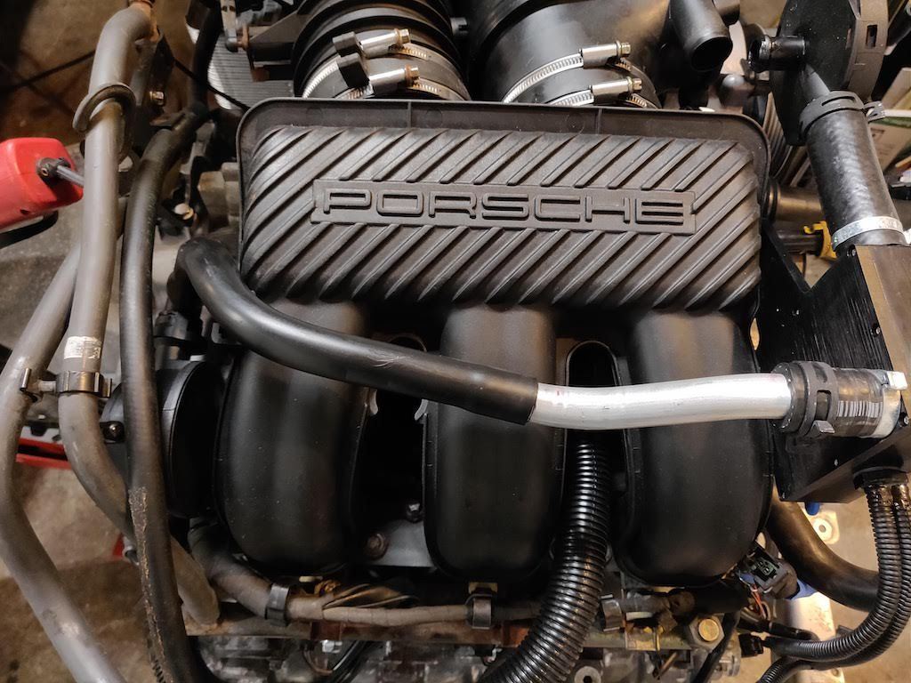
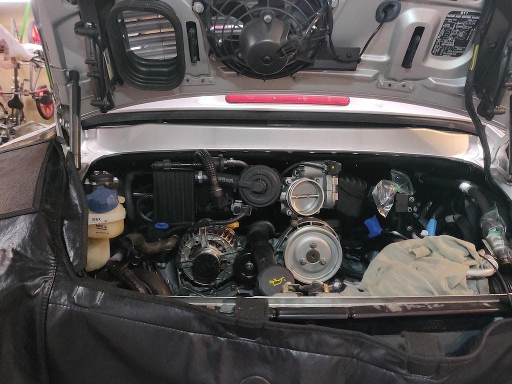
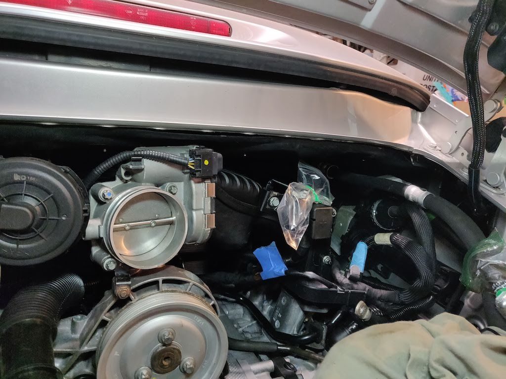
Before I installed the engine, I installed the missing transmission bolt, installed the U-AOS, and smoke tested the engine for potential vacuum leaks. I had a leak in the front throttle body crossover tube that I was able to fix before the engine went in the car.
I am hoping to start the engine this weekend if all goes well. Still have a lot of little items to install though.
Here are pictures of the progress
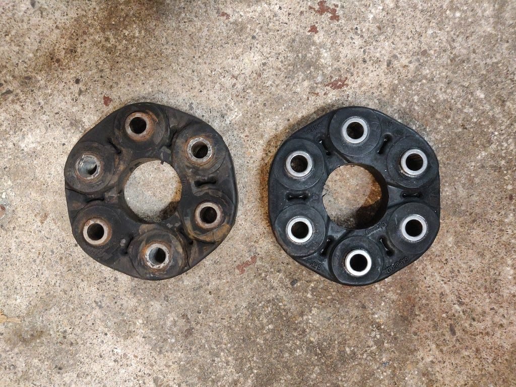
Here is my homemade smoke machine. It worked really well. U-AOS tube U-AOS tube installed U-AOS installed All done and ready to install. Before I installed the engine, I replaced the disc that connects the transmission to the front drive shaft. Mine was cracked and worn. I used string and weights to line up the engine before raising the table and lowering the lift. Due to the width limitation of the lift, I needed to install the muffler mounts once the engine cleared the lift, but before the engine was in the bay. I did remember to plug the coil back in. Here is the engine installed.
The engine is ready to go except for fluids, and a few wires, some small parts, and a final once over. I wanted to wait until tomorrow when I wasn't so tired from working on the car. A good night's sleep and a clear head will make me feel better when I inspect everything and do the final checks.
As a note, working on these cars is like working on a jigsaw puzzle. There are so many unrelated parts that need to be installed in the proper order so you can reach bolts and fit parts. I am glad that all the difficult parts are done.
Lastly, I did have a few issues since the last update.
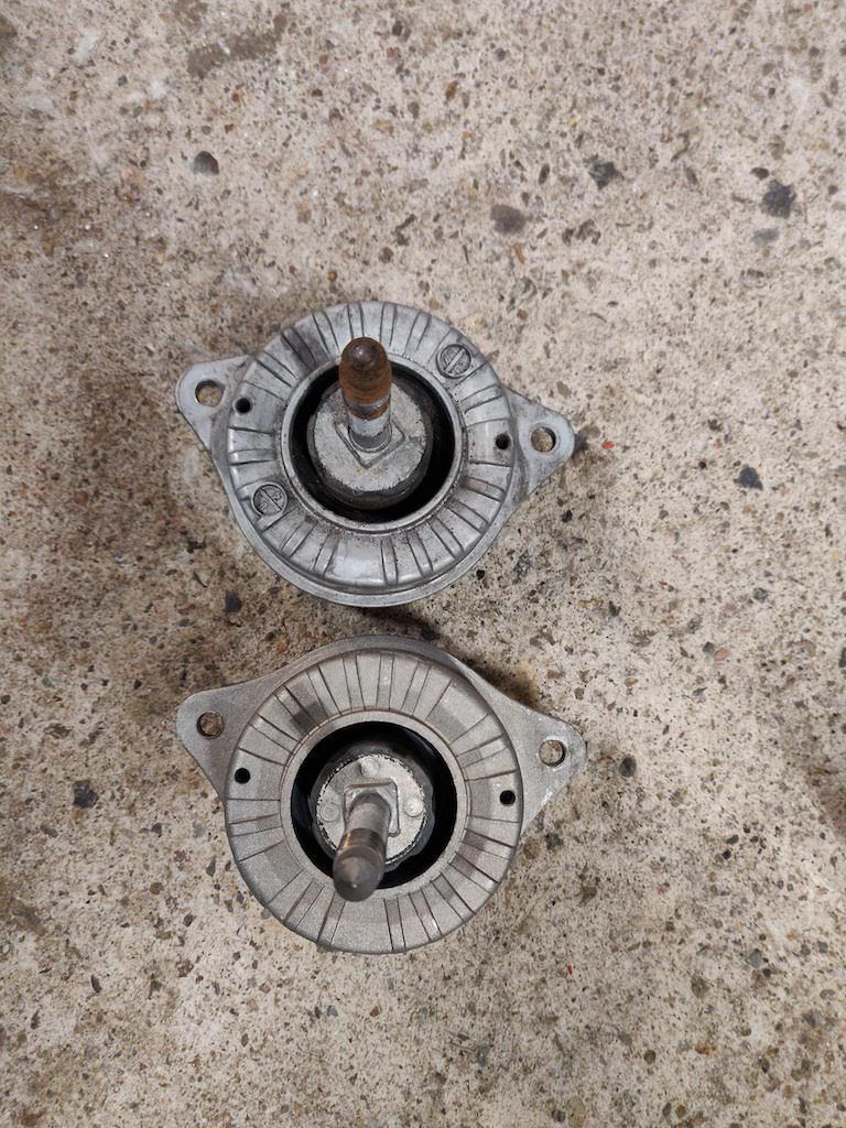
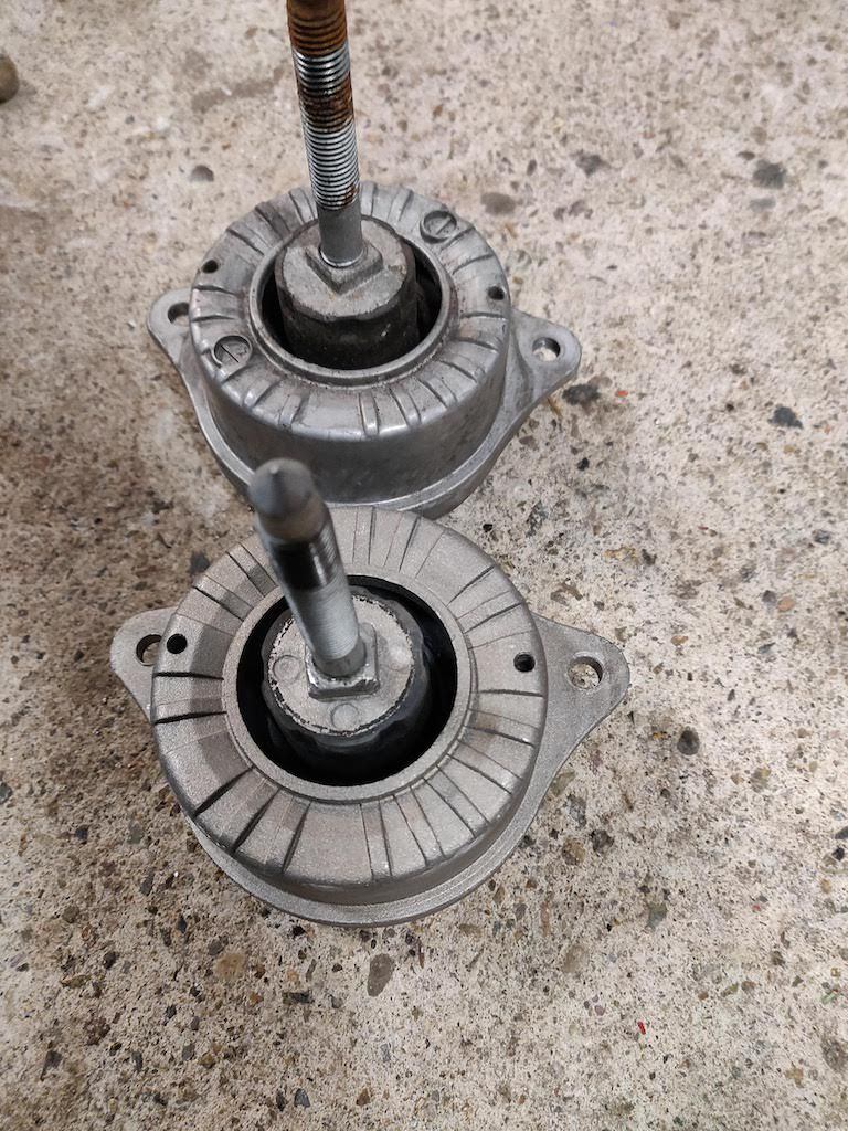
The first issue is my new Uro engine mounts don't line up. The square that hooks into the carrier is clocked wrong on both my mounts. I had to install my old blown out mounts until I get the Uro ones returned and replaced.
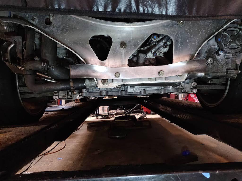
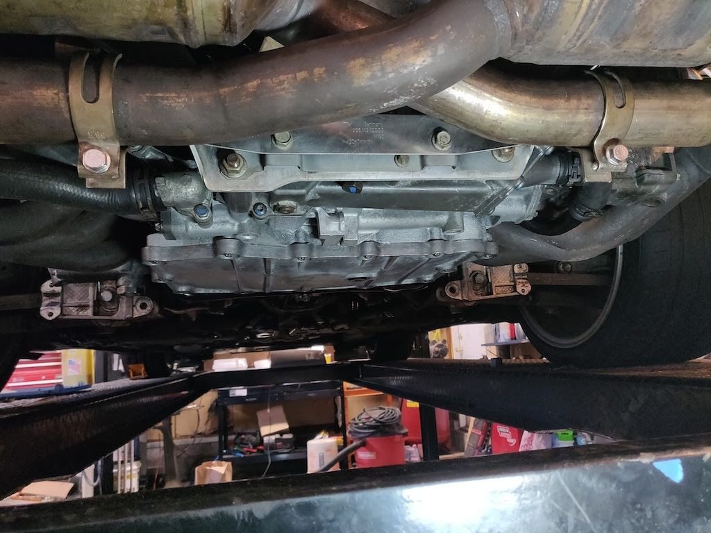
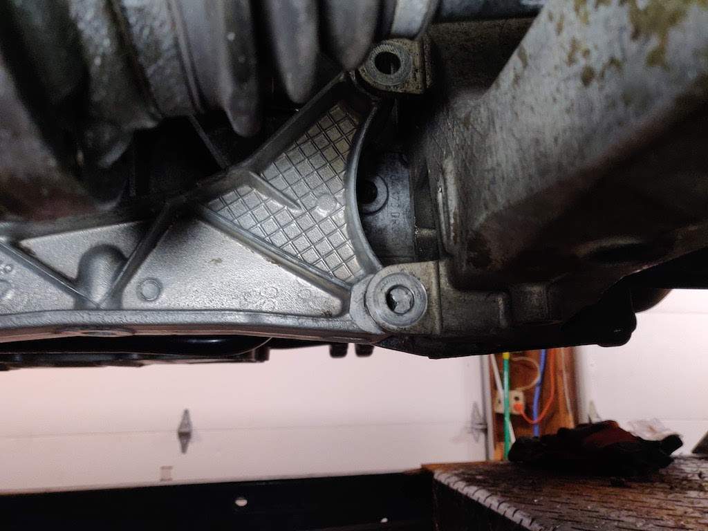
The second small issue is my engine crossmember isn't lining up. I'm sure I just need to jack the car up and that will get it lined up. If not, I may need to get creative with some ratchet straps.
Here are pictures of the progress.
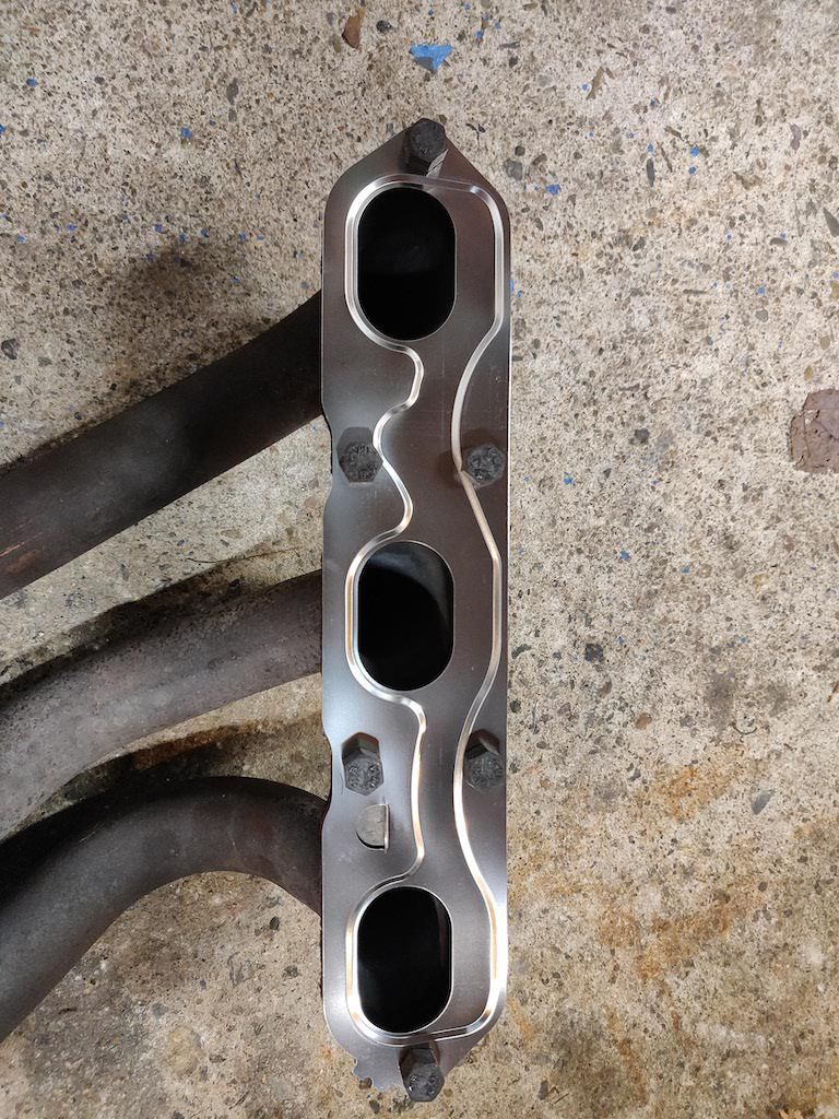
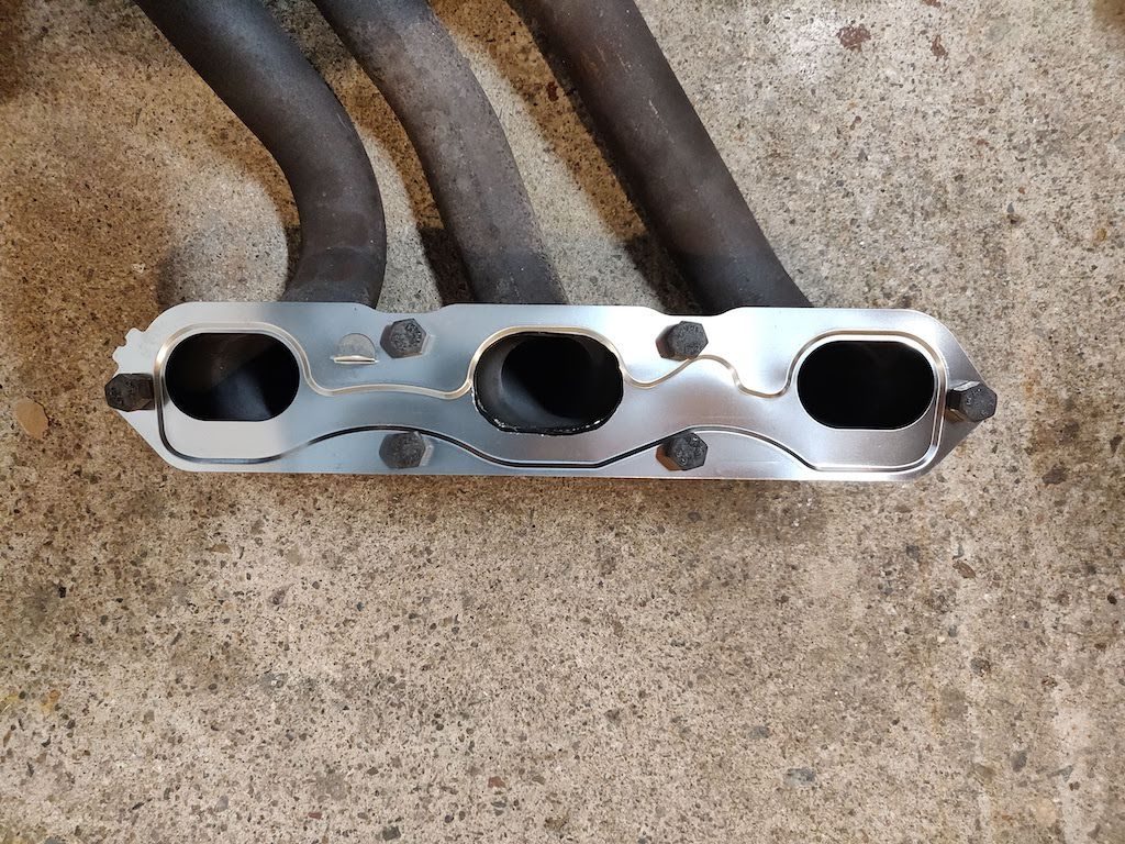
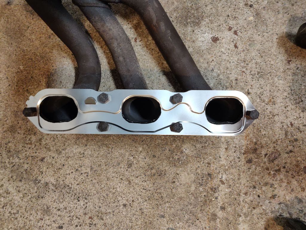
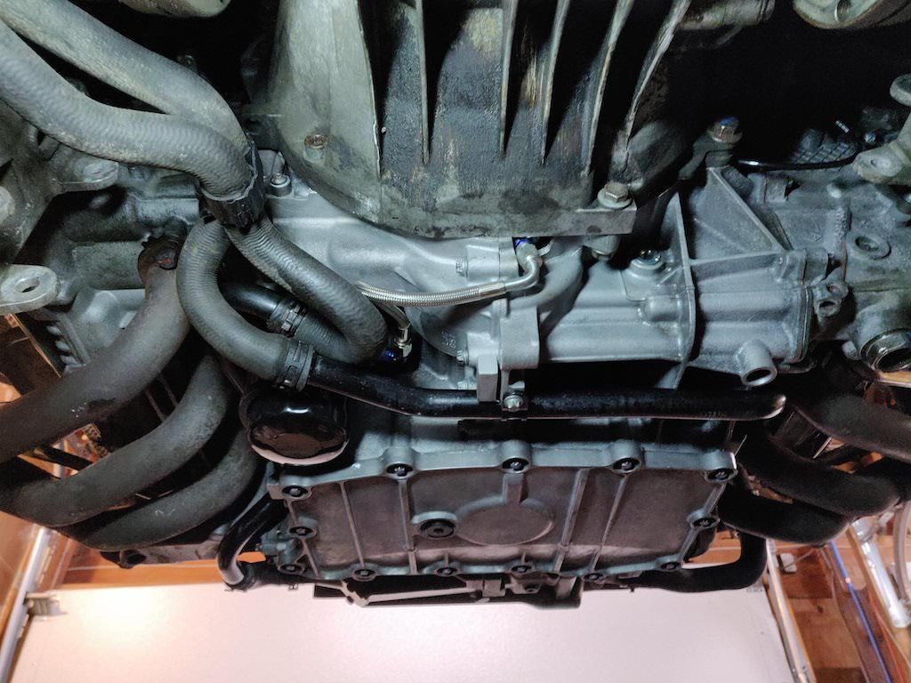
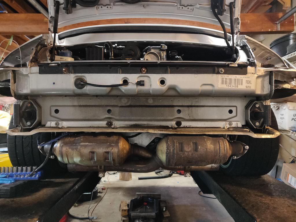
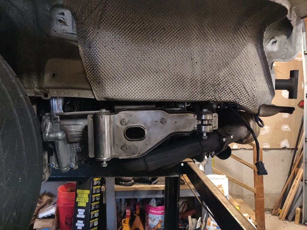
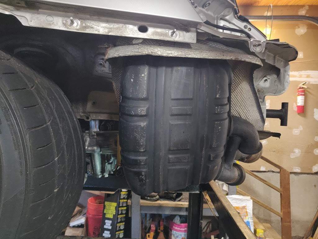
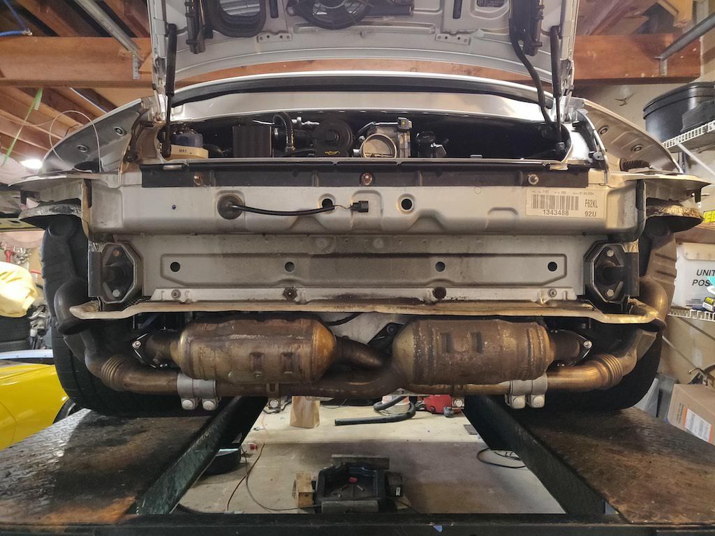
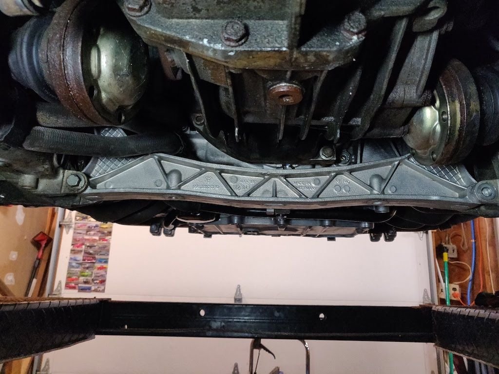
Top end of the engine done. Here are the new and old motor mounts. Notice how the squares are in different positions. Here is the exhaust manifold gasket that came in my kit. The gasket holes are smaller than the actual exhaust opening. I put the gasket on the manifold and took a die grinder to the center port. This matched the gasket size with the exhaust size. All three are done in this photo. Here is the bottom of the engine all complete. I went with factory bolts and loaded them up with anti-sieze. Next step was installing the catalytic converters. In case anyone is wondering, you need to install the left side first then the right side. I found this out the hard way. I still need to plug the 02 sensors in. Here is a shot of the bottom of the engine from the back of the car. This is the mount that the mufflers to attach to. I picked these up used because mine were rusted out and some of the studs were broken. For reference, it's much easier to install these with the exhaust manifolds not installed. Unfortunately, I did not do this. Here is the left muffler installed. I lathered up the bolts with anti-sieze so they won't rust again. I also installed the bolts from the bottom so the mufflers can be easily removed in the future. These are mufflers I picked up used from a fellow member for cheap. Mine were rusting at the seams and needed to be replace. Here is the full exhaust install without the tips. I used new clamps to install the mufflers to the cats. I also used new stainless bolts in the brackets that hold the cats to the holder. Here is my crossmember installed. The bolt is installed in the passenger side, but the driver side is not aligning. Here you can see how far off the hole is. Only 1/3 of the hole in the crossmember is visible.

 01-21-2022, 06:21 PM