When you click on links to various merchants on this site and make a purchase, this can result in this site earning a commission. Affiliate programs and affiliations include, but are not limited to, the eBay Partner Network.
Somebody like PorscheTech could experiment with this configuration pretty cheaply:
Install cylinder head oil restrictors as I have described elsewhere. (5 chain engines only as I have not developed these for 3 chain engines yet)
Use an X51 style pump to scavenge the intermediate shaft area instead of a cylinder head. My system is optimized for mid engine installation and this may actually be important. It does not look possible to relocate this scavenge point to the "back" of a 996 engine.
Sump of your choice. I don't think any commonly available sump is measurably better than stock.
There is a decent chance this will do the job.
Chris Cervelli
Cervelli Technical Service
Chris, I get cha, using the second stage of the dual stage pump, run the pipe to the intermediate shaft area instead of the bank 2 head front side..not a bad idea... Since the 3.2 Boxster is the same as the 3.4 996 oiling system, what do you calculate the pressurized oil flow volume at both with and without the head restrictors you mentioned?
This is good insight. So I hear you saying hypothetically, that if the X51 kit was reworked to connect into the intermediate shaft area, that this may provide better oil flow from the valves down to the oil pan?
This is good insight. So I hear you saying hypothetically, that if the X51 kit was reworked to connect into the intermediate shaft area, that this may provide better oil flow from the valves down to the oil pan?
Glen, yes exactly, but you must realize this is light conversation between two Technically experienced people. We may talk light about simply introducing a port into an oil location, but we understand it would need to be done with the engine disassembled to keep metal chips from being a problem. And the commercialization of such an idea would be a lot more than light technical talk.
In other words, the idea has Technical merit, but to commercialize the idea for consumer benefit is a whole other ballgame.
Glen, yes exactly, but you must realize this is light conversation between two Technically experienced people. We may talk light about simply introducing a port into an oil location, but we understand it would need to be done with the engine disassembled to keep metal chips from being a problem. And the commercialization of such an idea would be a lot more than light technical talk.
I do have a way to do this on an assembled engine, but it requires more skill with tools and attention to detail than the hobbyist (heh) is going to have in most cases.
My data shows that the head restrictors and resulting slower oil pump speed raise the oil level in the tank by around 2 quarts. If, on a wet sump engine, the same thing happens in the sump, then it's likely that the problem will be greatly mitigated if not solved.
I don't have data on the contribution of the intermediate shaft area scavenge point. My mental model of the oil capture inside the engine has most of the oil here and in the chain boxes, and this scavenge point (mid engine) is effective under acceleration, or roughly 80% of a lap. The reverse will be true in a 996. If I am correct that this area is full of oil all the time, then this won't matter much. If it is true that only a small amount of oil is present there, then my above proposal will not work.
If someone wants to try this on a 5 chain engine and publish the results with data, contact me and I will send you a set of restrictors and instructions on their installation and the installation of the scavenge point. The cylinder heads have to be removed to install the restrictors. I have some double scavenge pumps lying around too.
Glen, yes exactly, but you must realize this is light conversation between two Technically experienced people. We may talk light about simply introducing a port into an oil location, but we understand it would need to be done with the engine disassembled to keep metal chips from being a problem. And the commercialization of such an idea would be a lot more than light technical talk.
In other words, the idea has Technical merit, but to commercialize the idea for consumer benefit is a whole other ballgame.
Skip, understood! Just trying to keep up with you guys and try to follow along. Any corrections to what I attempt to summarize are appreciated. More so, I appreciate the conversation that you and Chris bring to the thread.
I do have a way to do this on an assembled engine, but it requires more skill with tools and attention to detail than the hobbyist (heh) is going to have in most cases.
I know what kind of procedure you speak of, it involves a high flow vacuum source and a special drilling/milling tool and yes "skillz"..The procedure could also be used to open up the 4 6mm drain back holes in the "loft area" to 10mm to help with drain-back from the loft. Easily done during rebuild, but could not be commercialized in situ for consumer benefit.
Anyone want to calculate the increase in oil flow from 4 6mm holes to 4 10mm holes under gravity at 212F ?
Originally Posted by CTS
My data shows that the head restrictors and resulting slower oil pump speed raise the oil level in the tank by around 2 quarts. If, on a wet sump engine, the same thing happens in the sump, then it's likely that the problem will be greatly mitigated if not solved.
2qts less in the "loft area" and 2qts more in the "Integral Dry Sump" is very substantial and I agree this may solve the whole issue.
The cost to do this would probably be about 20 hours labor for consumers @ $175hr average =$3500 labor plus about $400 parts so for about $4k a consumer could have this done.
But this would be a pretty "invasive" and costly procedure to eliminate the problem on a otherwise healthy engine
Originally Posted by CTS
I don't have data on the contribution of the intermediate shaft area scavenge point. My mental model of the oil capture inside the engine has most of the oil here and in the chain boxes, and this scavenge point (mid engine) is effective under acceleration, or roughly 80% of a lap. The reverse will be true in a 996. If I am correct that this area is full of oil all the time, then this won't matter much. If it is true that only a small amount of oil is present there, then my above proposal will not work.
Looking at the loft area, the oil in the Intermediate Shaft area has two ways to get to the Integral Dry Sump. On accelerating and turning left It can drain through the 4 6mm holes back to the sump, or it can go out the chain box to the bank 2 scavenge pump, on braking and turning right it can drain through the 4 6mm drain holes or go out the chain box to the bank 1 scavenge pump. The right turns are also where the AOS get overloaded with a rush of oil and blow-by that is too fast for the pump to handle all at one time. Increasing the drain holes to 10mm may provide enough drain back fast enough for substantial increase in sump function.
[QUOTE=CTS;17547526If someone wants to try this on a 5 chain engine and publish the results with data, contact me and I will send you a set of restrictors and instructions on their installation and the installation of the scavenge point. The cylinder heads have to be removed to install the restrictors. I have some double scavenge pumps lying around too.
Chris Cervelli
Cervelli Technical Service[/QUOTE]
Originally Posted by GC996
Skip, understood! Just trying to keep up with you guys and try to follow along. Any corrections to what I attempt to summarize are appreciated. More so, I appreciate the conversation that you and Chris bring to the thread.
Thanks Glen I hope you ( and everyone else) can keep up, the knowledge gap between Techs and consumers can cause so much confusion , thanks for your understanding. I am sure it would be like me trying to follow along with you and a colleague on high level Investments.
Last edited by Porschetech3; 07-13-2021 at 04:18 PM.
Anyone want to calculate the increase in oil flow from 4 6mm holes to 4 10mm holes under gravity at 212F ?
Looking at the loft area, the oil in the Intermediate Shaft area has two ways to get to the Integral Dry Sump. On accelerating and turning left It can drain through the 4 6mm holes back to the sump, or it can go out the chain box to the bank 2 scavenge pump, on braking and turning right it can drain through the 4 6mm drain holes or go out the chain box to the bank 1 scavenge pump. The right turns are also where the AOS get overloaded with a rush of oil and blow-by that is too fast for the pump to handle all at one time. Increasing the drain holes to 10mm may provide enough drain back fast enough for substantial increase in sump function.
This all assumes that the atmospheric conditions inside the engine allow any oil to drain thru these holes when the engine is running. I think they were put there so the oil would all drain into the sump when the engine was stopped.
This all assumes that the atmospheric conditions inside the engine allow any oil to drain thru these holes when the engine is running. I think they were put there so the oil would all drain into the sump when the engine was stopped.
Chris Cervelli
Cervelli Technical Service
I agree, using a "Factory AOS" means the engine would be running 5 inches of water less that Atmosphere pressure(3.5 inh20 on UAOS) and may not be the same all through the "loft" and Integral Dry Sump,.
Maybe an even more simple solution would be a "balance tube" to equalize the pressures between the two
Actually the high mileage/Extreme Track Duty Auto-Drain hose does this to an extent, it connects the Loft area to the crankshaft area that has direct flow to the sump.
Last edited by Porschetech3; 07-13-2021 at 04:51 PM.
The sump area has to be under high pressure because the blow-by gasses are directed there by the plastic guide around the intermediate shaft. Porsche even took the trouble to seal that plastic against the case halves. The intermediate shaft area, the chain areas, and the cam/lifter areas would all be under lower pressure due to the scavenge pumps sucking the air and/or oil out all the time. Furthermore, with an AOS in use, the pressure is dropped even further in these areas from the limited manifold vacuum applied thru the AOS.
The blow by gasses's path out to the AOS is not obvious. I thought the AOS drained liquid oil thru the diagonal passage down to the sump but maybe that's how the blow-by gasses are supposed to escape. That would mean in times of high blow by (usually this is high rpm, Throttle >10% and <50%) the AOS cannot drain. That would explain the smoking tendency all by itself.
In a dry sump system, having the tank under a little pressure makes sense. In the case of an M96, this seems counterproductive because the high pressure in the sump slows the drain back due to gravity.
I always have a hard time thinking that Porsche screwed this up so bad. I must be missing something.
Chris Cervelli
Cervelli Technical Service
The AOS is drained from the cyclone down through a funnel shape in the AOS into a 14mm drain hole to the sump under the oil level. The UAOS high mileage/Extreme Track Duty Auto-Drain connects the Accumulator to the oil fill tube which is directly over the crankshaft area and drains down through the plastic guide directly to the sump.( adding another drain path)
The blow-by gasses and flow are directed out of the top of the crankcase above the crankshaft carrier up the chain boxes to the heads where the AOS vent pipes are located, directly above the scavenge pumps.
The sump area has to be under high pressure because the blow-by gasses are directed there by the plastic guide around the intermediate shaft. Porsche even took the trouble to seal that plastic against the case halves. The intermediate shaft area, the chain areas, and the cam/lifter areas would all be under lower pressure due to the scavenge pumps sucking the air and/or oil out all the time. Furthermore, with an AOS in use, the pressure is dropped even further in these areas from the limited manifold vacuum applied thru the AOS.
The oil goes down thru the plastic guide and blow-by gases goes upwards an escapes to the AOS ports on left/right head...I don't think it's air/oil tight on the top. The sump would be under pressure due to the scavenge pumps but the small holes let those gases escape....thus not much oil goes down these holes since air is flowing the opposite way. Edit: that can't be correct. Gases have to mainly escape thru the short block and up. There should be a small overpressure in the sump but it might be so small it's not possible to measure and can thus be ignored. The main task of the holes is thus to drain back oil when engine is off.
FWIW the entire "air space" in the engine is under Atmospheric pressure (14.7psi) minus 0.2psi ( 5inh2o for AOS ) except for turbulence and windage caused by the rotating of the crankshaft and pumping of the pistons (bottom side) and the respective cross windage pumpage.
The pressure in the Integral Dry Sump is the same as everywhere else and can easily be verified by testing at the dipstick tube, which goes directly to the Integragted Dry Sump unobstructed. I just did it to confirm what I already knew.
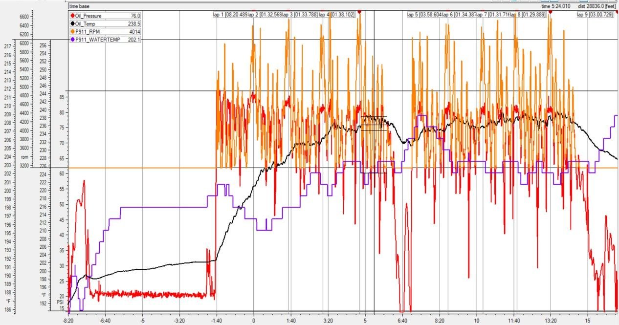
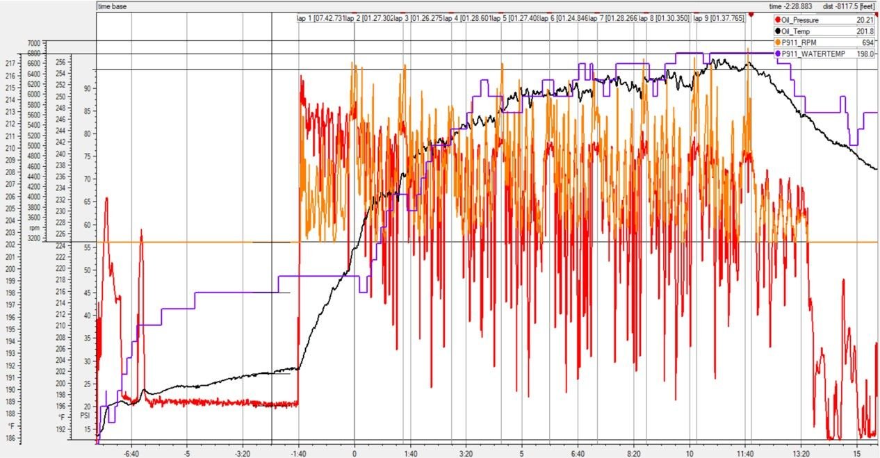
Here's a look at Jason's run today. This is the overview. The second chart is the overview from 6/27 previously posted. Both have oil filled to 1/2 on the dipstick. Both have the blow by oil return from the UAOS. The huge differences are in temperatures and a wet track limiting speed. The difference is clear. We can say the obvious: a cooler engine has fewer pressure problems. Look at the difference in the red graph drops between the 2 sessions. Quite striking.
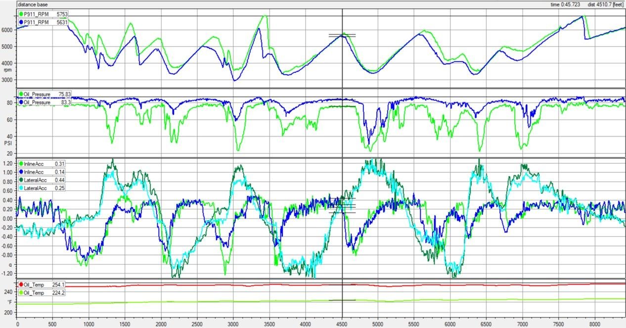
Here's a look at the personal best lap from 06/27 and the best lap of this run. Green lines are from 6/27. Blue are 7/13.
-The overall pressure is higher. This is a little surprising given the bypass valve. My guess is that this shows the difference in viscosity of the oil due to the lower oil temp.
The interesting peak to look at is at 4800ft. The G's on the right turn are the same. The RPM's are the same. Because of this, we can assume the difference in the pressure change is only due to the oil temperature. The total time the hot lap is bobbling around under the bypass pressure is around 8 seconds(4700-5400ft). The time for the cold lap is around 5(4800-5300ft).
My list of next steps would be:
-center rad
-bigger oil cooler (available?)
-thicker oil
Given the known blow by on this engine, the thicker oil will probably help more than just pressure drops. What issues does thicker oil present on the track?

 07-12-2021 | 09:28 PM