

Public-domain OBD1 PCB board - ORDER HERE
 09-14-2006 | 10:35 AM
#136
Addict
Rennlist Member
Rennlist Member
Joined: Nov 2001
Posts: 554
Likes: 3
From: Herefordshire
Originally Posted by cowtown
I mailed out the Raycm circuit boards this morning.
Have fun guys,
Colin
Have fun guys,
Colin
Thanks once again ! cheers, Maurice
 09-14-2006 | 10:39 AM
#137
Instructor
Joined: Feb 2005
Posts: 190
Likes: 0
Chris, I may have missed this, but need to know how to determine plug type for the assempled unit. I have a US spec MY 95 and know it is OBD1, but are there variations that I need to tell you about for my assembled unit?
09-14-2006 | 12:14 PM
#138
Thread Starter
Racer
Joined: Nov 2003
Posts: 424
Likes: 0
Maurice- the board measures 2.5 inches by 3.8 inches. On an XY grid, the screw hole centerline coordinates are:
0.30, 0.22
3.50, 0.22
0.30, 2.28
3.50, 2.28
Sumtoc, the later OBD2 style connected (which I have on my '95) is a parallelogram in shape. These are around $5 and very common. The earlier 964 (and possibly some early 993) connector is round. The 964 guys seem to be having a hard time finding them because AMP is no longer manufacturing them. So a little creativity might be required (pins into the plug, a home-made plug made from a receptacle, etc.). Check the 964 thread (linked in my first post here) for some creative solutions.
964 Style:
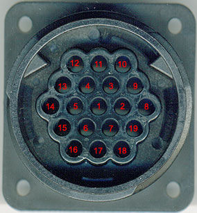
993 Style:
0.30, 0.22
3.50, 0.22
0.30, 2.28
3.50, 2.28
Sumtoc, the later OBD2 style connected (which I have on my '95) is a parallelogram in shape. These are around $5 and very common. The earlier 964 (and possibly some early 993) connector is round. The 964 guys seem to be having a hard time finding them because AMP is no longer manufacturing them. So a little creativity might be required (pins into the plug, a home-made plug made from a receptacle, etc.). Check the 964 thread (linked in my first post here) for some creative solutions.
964 Style:
993 Style:
09-15-2006 | 03:54 PM
#139
Rennlist Member
Joined: Nov 2004
Posts: 1,796
Likes: 5
From: San Francisco
Got the board, thanks!
Q about C1, C2, C3. The schematic shows C1 as .22uF, but the BOM shows the following:
C1 0.1uF 25 Volt (such as Vishay A104K15X7RF5TAA or K104Z15Y5VE5TL2)
(C2) 100uF (such as Vishay 515D107M025AA6A)
OR (not preferred)
C1 .22u
The board has a spot for C1, C2 and C3, which are all in parallel.
What is the correct capacitance for C1? Should there be a big (100uf) electrolytic for C1 and small ceramic or silver mica or something for C2?
Thanks.
09-15-2006 | 06:41 PM
#140
Thread Starter
Racer
Joined: Nov 2003
Posts: 424
Likes: 0
Glad they are arriving. I used a .22 on my previous revision board and it works, but Ray has recommended better power filtering, hence the 0.1uf and 100uf parts.
When I build my new board, I'll go with 0.1uf in the C1 spot and an additional 100uf. You can see I put a bunch of extra holes and traces in (c2 and c3) for more capacitors. Might want to ask Ray in his support thread if there are any updates. https://rennlist.com/forums/993-forum/294027-diy-1995-obd-1-scantool.html
When I build my new board, I'll go with 0.1uf in the C1 spot and an additional 100uf. You can see I put a bunch of extra holes and traces in (c2 and c3) for more capacitors. Might want to ask Ray in his support thread if there are any updates. https://rennlist.com/forums/993-forum/294027-diy-1995-obd-1-scantool.html
 is there a list of stuff to solder to it, or do I just wave it over my engine and say ooga booga?
 09-16-2006 | 07:55 PM
#143
Three Wheelin'
Joined: May 2005
Posts: 1,706
Likes: 19
From: oceanside, ca
Originally Posted by brucec59
Got the board, thanks!
Q about C1, C2, C3. The schematic shows C1 as .22uF, but the BOM shows the following:
C1 0.1uF 25 Volt (such as Vishay A104K15X7RF5TAA or K104Z15Y5VE5TL2)
(C2) 100uF (such as Vishay 515D107M025AA6A)
OR (not preferred)
C1 .22u
The board has a spot for C1, C2 and C3, which are all in parallel.
What is the correct capacitance for C1? Should there be a big (100uf) electrolytic for C1 and small ceramic or silver mica or something for C2?
Thanks.
Q about C1, C2, C3. The schematic shows C1 as .22uF, but the BOM shows the following:
C1 0.1uF 25 Volt (such as Vishay A104K15X7RF5TAA or K104Z15Y5VE5TL2)
(C2) 100uF (such as Vishay 515D107M025AA6A)
OR (not preferred)
C1 .22u
The board has a spot for C1, C2 and C3, which are all in parallel.
What is the correct capacitance for C1? Should there be a big (100uf) electrolytic for C1 and small ceramic or silver mica or something for C2?
Thanks.
09-16-2006 | 09:43 PM
#144
Instructor
Joined: Dec 2005
Posts: 132
Likes: 0
I built and tested the latest pcb today. Its a keeper. All works.
.1uF and 100uF are good. It would probably work with no cap but noise tolerance not good. The longer your cables the more noise. You could buy most any values if you don't see the ones I reccomend. Be sure working voltage is 25V or greater. I published a schematic. But the LEDs parameters need added to parts list. I installed the fuse. Its a "in case" item. Not needed but if you drop a screw driver in the works the fuse is handy to have. 1/4 AMP > 15V DC. Which means a 1/4 AMP 120V AGX fast blow works, or anything larger. The circuit draws less than 50mA.
LEDs. VF of 1.4 volts. No bias resistor. LEDs wont see more that 15mA. Color must be red to match my Porsche! You can leave LEDs out but must install jumper in their place. If you install LEDs and they don't glow when the OBD interface cable is connected, they are either in backwards or they require more than 1.4V to lite (wrong type). Either case will prevent interface from talking to OBD. A jumper short across each of the 3 LEDs will verify if they are the issue. Any other assembly error could also cause the LEDs to not glow. I'm belaboring the LEDs because there are a large number of models available. This is not the case with the other components.
I buy parts from Newark In One. www.newarkinone.com They send me a 2500 page catalog. Nice place to do business.
The 964 group has a running thread on scantool. Just remember, mostly they are using someone elses interfaces and the problems/fixes are not aplicable to this interface. Same is true of their scantool.cfg, & error code list.
Coming home from autox last week I felt the engine had a high resonance. I connected scantool and ran TEST OUTPUTS. The resonance flap worked fine and no error codes. I then found the problem was I didn't put in all the screws on the under engine cover. Too bad I can't run scantool on my laptop. It crashed and I'm struggling with MS to get it fixed.
Ray

 09-17-2006 | 12:44 PM
#149
Addict
Rennlist Member
Rennlist Member
Joined: Nov 2001
Posts: 554
Likes: 3
From: Herefordshire
Originally Posted by raycm
I built and tested the latest pcb today. Its a keeper. All works.
LEDs. VF of 1.4 volts. No bias resistor. LEDs wont see more that 15mA.
If you install LEDs and they don't glow when the OBD interface cable is connected, they are either in backwards or they require more than 1.4V to lite (wrong type). Either case will prevent interface from talking to OBD.
Ray
LEDs. VF of 1.4 volts. No bias resistor. LEDs wont see more that 15mA.
If you install LEDs and they don't glow when the OBD interface cable is connected, they are either in backwards or they require more than 1.4V to lite (wrong type). Either case will prevent interface from talking to OBD.
Ray
Q on the leds - I guessed 2.2V VF when ordering, but when looking for VF = 1.4, the lowest I can get is 1.6 .. is it that critical ?
cheers, Maurice
