When you click on links to various merchants on this site and make a purchase, this can result in this site earning a commission. Affiliate programs and affiliations include, but are not limited to, the eBay Partner Network.
My friend Martopoulos, after checking all possible solutions, the problem was in the brandwith of the VAS Clone interface. Apparently it has problems coding PDLS+ (found this on a Russian forum). I took an original interface with the same software and within 2 minutes the job was done...
Thank you the tips you gave me it helped me make sure all the hardware was not the problem.
I�ve been trying to code my replacement passenger side headlight (pdls+) and have been running into these errors. The driver side headlight is the car�s original and used to function but since the coding I messed it up and has stopped working too.
the only thing that works now is the drl (4dots) on the passenger headlight when the ignition is switched to off and the moment I turn the ignition everything on the headlights dies.
any suggestions on what might be the cause?
(the passenger side headlight and modules are replaced with used ones ( headlight: 99163196812, modules: 7opp941572bb, 7pp941329t) and everything on the driver side is original and used to function as normal up until I messed up the coding.)
Here's a very quick and dirty guide on how to go from Xenon headlights to LED headlights. I've done this on my own car already, so if anyone has any questions feel free to ask in the comments.
PDLS Plus Retrofit - Required parts
7PP.907.357 Beam Leveling Adjustment Module
2x - 7PP.941.329 LED Controller
2x - 7PP.941.572.BB, 7PP.941.572.B, or 7PP.941.572.A LED Power Supply
7PP.980.653 Camera *
991.555.715.00 Camera Glass Defroster *
991.555.625.01 Camera Mount, Windshield (Incl. w/ windscreen) *
991.541.911.15 Windshield, Camera Mount, Tinted Upper *
LED Headlights (Part numbers vary)
* = optional for automatic high beams. You do not need these parts for LED lights, but you will get an error in the instrument cluster telling you that high beam assist is unavaialble.
Connectors/Wiring:
185879-2 or 7M3-972-726-A - Connector for AFS Module 26 Pin Blue
8D0-972-623-A - Connector for Camera Heater Module
2x 1J0-973-735-A (or 2x TE# 493577-2, 20 terminals TE# 1241872-1, 20 wire seals 828904-2) - Connector for LED Headlamps
1534096-1 - MQS (Micro Quadlock System) Connector Housing, 6x2 for Camera Module.
1534100-1 - MQS Connector Plug, 6x2, for Camera Module
144969-1 - MQS Terminals, Tin Plated, 20pcs roughly.
Other:
Fabric Wiring Loom Tape
Silicon RTV Sealant
Extraction tool for headlight JPT connector (1-1579007-6) or suitably long and narrow tweezers, bent inward at the tips (Hakko CHP 3-SA).
Wire Taps, 18-22AWG
Wire: Twisted pair for canbus
Ratcheting crimp tool for 16-20 gauge wiring
Removing headlights:
991.2 owners - You need to remove the front bumper to remove your headlights, there are then 2 10mm bolts that must be loosened from the frame beneath the lights.
991.1 owners - Headlights are removed through the frunk with the included tool. Open the vertical flap on either side of the frunk, behind fix-a-flat kit and toolkit. Stick the end of the tool until it mates with the screw on the other end. Rotate tool about 180 degrees, or until the headlight pops forward. Refer to owner's manual for detail.
Wiring:
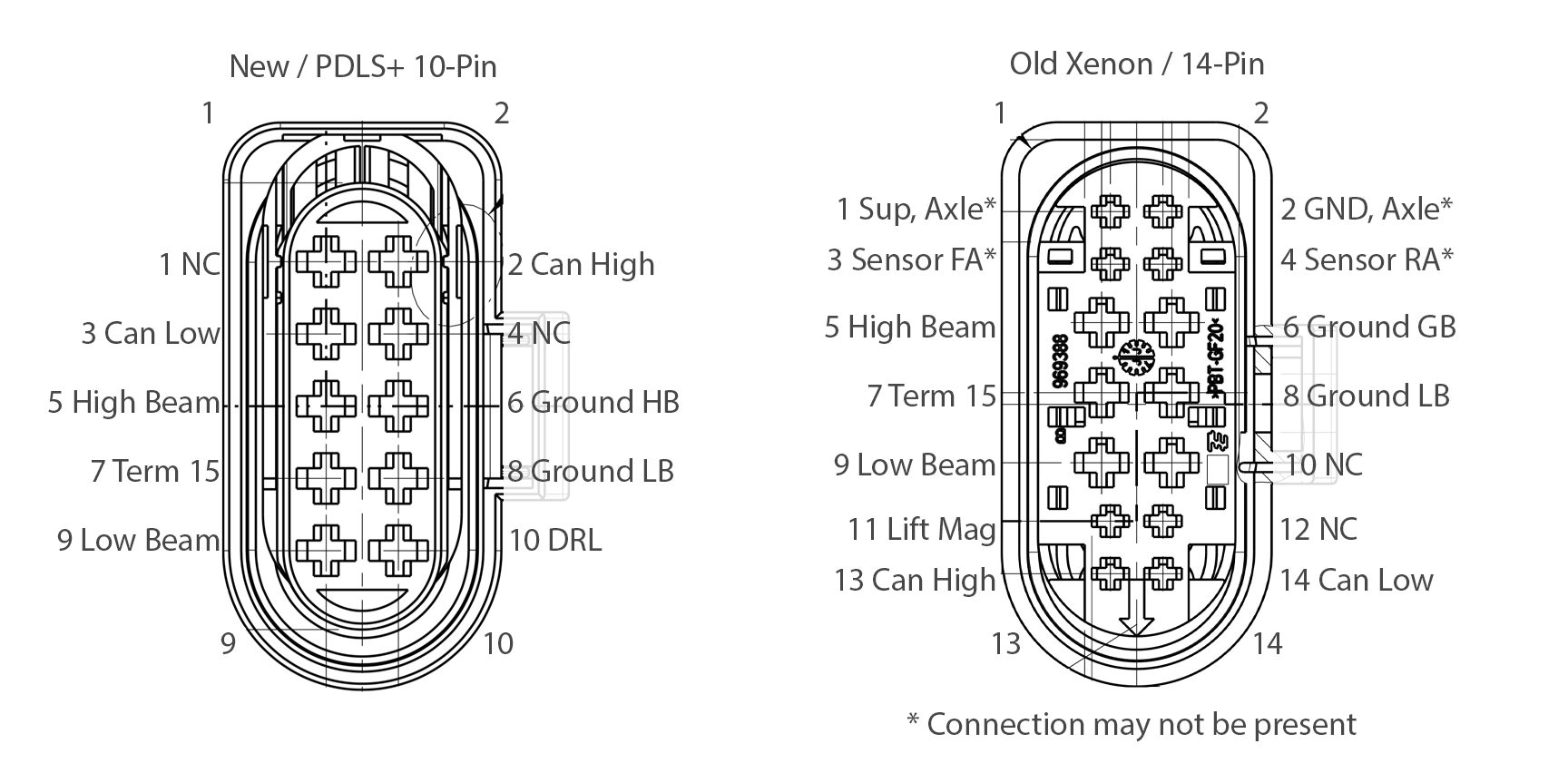
Re-Pin old 14-pin headlight connector to new 10-pin connector.
Start by transferring all of the wires from your old 14 pin connector. Repeat this procedure one by one for each connection to better keep track of the wires.
To do this, first move the connector into the open position by pushing the pink part of the connector against the directional arrow, you will hear a click.
Then take your removal tool and insert it into the connector housing above and below the terminals.
Simultaneously squeeze the tool together and pull the wire back out of the connector housing. You can also use the official TE extractor tool 1-1579007-6
Once you have pushed all wires out of the old connector, you may discard it.
You will install all wires to 10 pin connector except for orange + brown, orange + blue and the white w/ black stripe wire according to diagram.
Route can crash low + high wires from passenger side headlight to frunk for connection to leveling module. These are the orange + blue and orange + brown wires.
I would advise against splicing and actually pull the cable out of the harness and back into the frunk area. I was able to do this by grasping the wires from underneath the tire compressor with pliers and a microfiber cloth and gently pulling backwards.
Find the rubber wire grommet in the top left of the frunk, it is behind a plastic cover. Punch a small hole through here to snake wires through.
Snake wires through the rubber grommet in the top left area of your frunk.
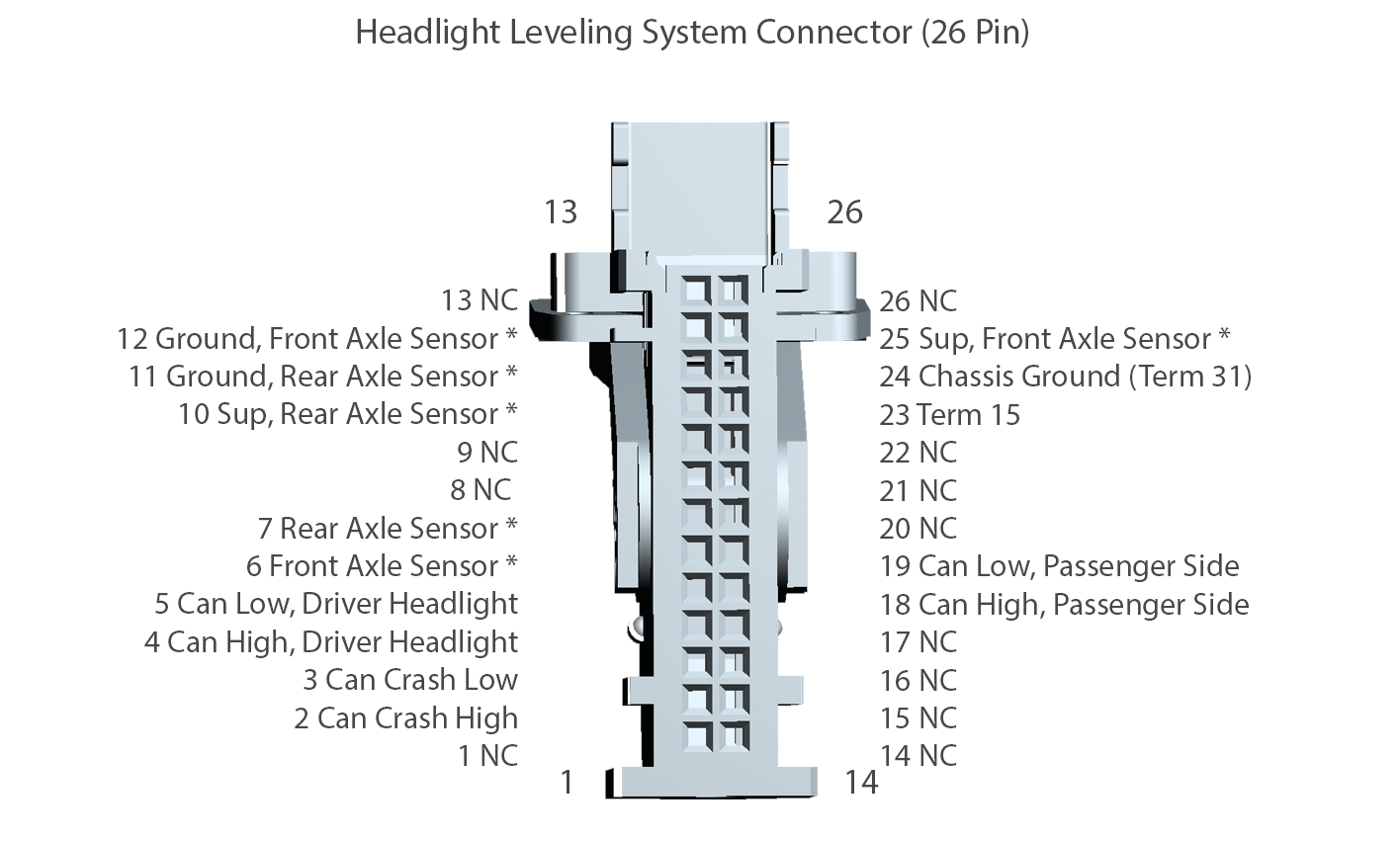
Crimp the two can crash wires and insert into 26 way MQS socket for installation into leveling controller. See image for pin locations
Crimp new CAN connections for headlights
Take two twisted pairs of wire, four wires total, and crimp them with MQS terminals. Install them into the appropriate connections on the leveling controller for headlight canbus. You can use old ethernet cable, but it may be too thin to adequately seal when installed in the headlight conectors. This is a low voltage/current line, so it doesn't matter electrically, but to obtain a proper seal, you should only use 18 gauge or higher wire.
Loom each pair of wire with fabric tape to protect it.
Run new twisted pair wires to both headlights from frunk / leveling module. Route wire through existing plastic heatshrink on the headlight end to protect it.
Crimp each wire with the sealed JTP connectors by stripping back wire jacket to expose a couple mm of copper wiring. Then insert the rubber seal over the wire jacket, and crimp with the front tab over the bare wire, and the rear tab over both the wire jacket and seal. The official TE crimp tool is extremely expensive, so you'll need to shop around and find a suitable generic ratcheting crimp tool
Install newly crimped wires into the appropriate positions in the headlight connector.
Connect DRL
The white + black (this is the thinner wire, white primary color with black stripe) is now unused, we will reuse this wire for DRL connection.
Cut the white + black wire in a location where we have enough length to attach it to the DRL wire. In my case, I found the wire in the main harness by buzzing it out with a multimeter and then cutting it closer to the frame rails. Plug one end of the wire and tape it back to the main harness, as it is unneeded.
Remove and disconnect the bumper wiring harness, which is located at the inside rear edge of headlight under tray. Use a flat head screwdriver to release clips and unmount connector from frame for better access. See photos.
You have two options: run both the existing DRL and PDLS+ DRLs, or run just PDLS+ DRLs. PDLS+ DRL cut the DRL wire in step 5, otherwise leave the DRL wires connected in place and simply tap your new wire into this.
Take the wire from pin 9 of the female (frame side) connector, this is the DRL line. Yellow + blue on the driver side and solid yellow on the passenger side.
Connect the DRL line to the end of the white and black wire that runs to the headlight. You must splice/tap this with a waterproof terminal to prevent corrosion.
Close headlight connector by pushing the pink locking tab in the direction of the arrow that is molded into the housing.
Your headlight connectors should look like my photo. Close headlight connector by pushing the pink locking tab in the direction of the arrow that is molded into the housing.
Connect and install headlights. Don't worry if they don't work properly at this point, this is normal since they have not been adapted to your car yet.
Finish Leveling Module
After connecting your three can lines (can crash, can private 1, can private 2) you just need to connect power
Find an ignition switched 12v power source for "Term 15". If you have homelink, this is available in the wiring harness that runs on the lower right side of the interior of the frunk. This wire is the yellow w/ red stripe wire.
To confirm you have the correct wire, pierce with a sharp multimeter probe and verify 12V with ignition on and 0v with ignition off.
Crimp a cable with an MQS terminal, insert it into the Term 15 position listed in the image, and then use a wire tap to connect the wire to this yellow and red line.
Crimp a cable with an MQS terminal, insert it into position for "Term 31", then connect it to any grounding point. There is a suitable ground point directly below the leveling module's mounting location, you may need to remove the floor pan to access it.
Mount the Leveling module to the left side of the frunk by securing it to the two studs that are welded to the frame
Connect any axle sensor wires that your car may have. These would have been connected to the left headlight if used.
Insert MQS connector into the blue MQS housing, secure the wire to the edge of the housing by looming it with fabric tape.
Install MQS connector into leveling module and use latch to secure.
Once all required connections are run through the firewall wiring gasket, re-seal it with silicon RTV sealant.
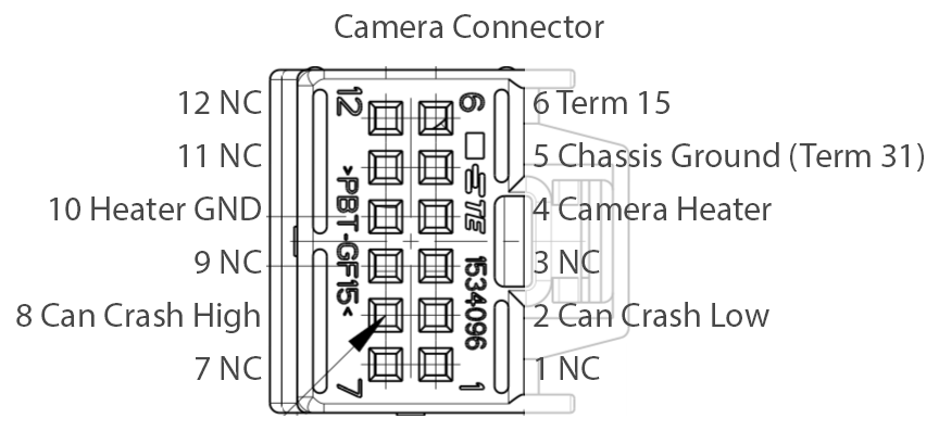
Connect Camera Module
This requires a new windshield. Have the windshield installed first, since the required mounting bracket comes pre-installed with the glass.
Tap ignition switched 12v (Term 15) and ground (Term 31) connections from mirror, install to appropriate locations in connector
Wire the heater connections by cutting two wires approximately 4 inches in length, then crimping both ends with MQS terminals. Install to appropriate positions on the camera connector, then install the other end in to the 8D0-972-623 connector
Tap (with twisted pair wiring) can crash low and can crash high from the can gateway. This is located in the driver's footwell above the OBDII connector, on the underside of the steering column. The required wires are orange + brown and orange + blue
Loom wires with fabric tape.
Route new can crash wire up the pillars and into the mirror assembly.
Crimp can crash wires with MQS terminals and install to appropriate positions in camera connector.
Follow prompts and select "execute" for each operation.
Programming is initiated for each module, wait for completion
During this process, software and data records are updated by PIWIS, coding is generated and headlights are matched to your VIN. You'll need to be in the car during this process as you will need to switch the ignition on and off
Restart car one final time, now you may test your headlights. If any codes are thrown in the cluster, or if something isn't working properly, go back and check DTCs and check your wiring.
Enjoy!
And what about the wiring to the level sensors? my car also does not have pdls so I have to retrofit the AFS module. According to the diagram, I should lead power, ground and signal to the sensors. Or maybe everything is done over CAN. I have air suspension.
Last edited by peterb1986; 06-30-2023 at 02:03 PM.
Does anyone know how to program the module to clear the PDLS error? Aftermarket lights installed and showing an error. Yellow headlight icon in the spedometer area.

 03-31-2023, 05:40 PM

 it helped me make sure all the hardware was not the problem.