When you click on links to various merchants on this site and make a purchase, this can result in this site earning a commission. Affiliate programs and affiliations include, but are not limited to, the eBay Partner Network.
https://rennlist.com/forums/993-foru...ml#post5110239
Speedo signal: black/blue wire from CCU unit (at least for 993)
Speedo signal: red/white wire from CCU unit (at least for 993)
Retro signal: blue/grey wire from CCU unit (at least for 993)
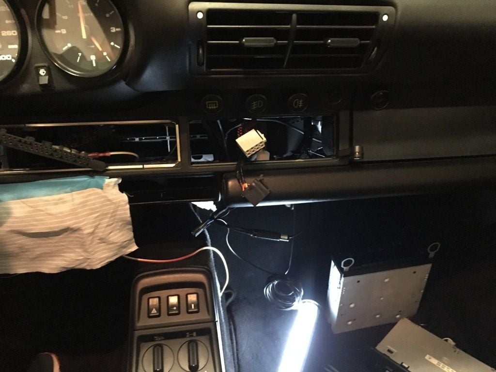
As you can imagine I am pretty confused.
I like the idea to take both signals from the CCU since it's close to the radio and easy to access but still I have no clue at which wires should I look at. If it helps I have a 1991 C4Cab manual.
Once some of you help me to identify the wires, then comes my second question. How to test if it's the right cable. I probably have at home a multimeter but I never used it. Instructions (as if you were teaching your dog how to bring back a ball) would be much appreciated.
Last but not least... which wire shall I use to bring the signal and how to attach it to the esisting wire. For the "radio end" seems simpler since you can use the ISO/DIN (I never remember the right name) to extract the pin and add the wire.
Sorry for the boring, long post, but I am somehow lost.
Speed signal is white/red wire in CCU pin G15. (large connector) This is a pulse signal, and you need a oscilloscope to verify it properly. You could also use a voltmeter, and roll the car very slowly forward to see the signal goes between +12V and 0V.
If you mean the reverse light signal from the gear box, this is available on CCU pin G21. (grey wire) This is 12V when you put the car in reverse.
Ciao Tore, thanks.
So G15 (white red) + G21 (grey), same large connector in the CCU (haven't' looked yet but I guess the connector has numbers on it ).
Couple of questions more...
1. Which kind of wire shall I buy? I mean, any electric wire will make the job?
2. How to connect it to the existing cable? I would like to make a "reversible" solution, so I would like not to use a t-tap connector. Of course I can make a small cut in the wire insulation and connect the other wire, but is there any "more elegant" solution?
You could use any wire since these signals does not carry any significant current. Taps and connection tecniques comes in many different variants. I prefer the 3M 558 connector, it is very reliable. Some prefer use soldering.
Cheers,
Tore
Sigh. Nothing. I miserably failed.
I did everything as expected but nothing.
With a wire-tap connector I linked the G15 from the CCU to the radio. Nothing happened.
G21 was not connected into the CCU but I could live without the reverse.
So, complete fail.
Well.. not really complete fail
I took the opportunity to add an AUX to the Becker Traffic Pro and I replaced the lighter housing that was broken but these were not the main goals.
Mission successful.
Now the speed signal is properly routed to the Becker.
The issue was that the wire-tap connector was not strong enough to break the "cable sheath".
I tried to find the retro wire as well with a multi-meter but with no luck.
G21 was empty in my connector (1991 C4 conv) and with a multimeter I checked all other connections but I was not able to find any cable that was giving me 12V with the retro gear in and 0V with gear in neutral.
BUT...
After the connection of the speed signal I went for a quick drive and the Becker immediately successfully completed the calibration (impossible until when the cable was not connected).
Very happy of the result.
Is there any updated map and SW that I shall buy on ebay?


 10-10-2016 | 01:51 PM