

Black Betty - Part 3 Engine rebuild
 10-10-2012, 02:28 PM
#151
Drifting
Thread Starter

If only it were that simple;-)
An ITB systems short length means its harmonics are 'tuned' to give maximum torque at high RPM's. At lower RPM's torque is lost.
The RS varioram manifold intends to create a best of both worlds by increasing length at low RPM's for optimal torque, and providing a shorter path at higher RPM. Your combination of 993RS type large ports with ITB's will noticeably hurt torque in the lower RPM region I'm afraid.
Above 7000RPM ITB's are king. Of course the cams used dictate at which point the engine gives max power, therefore which inlet system is best suited for max performance.
 10-10-2012, 08:43 PM
#152
Addict
Rennlist
Site Sponsor
Rennlist
Site Sponsor
Great info on your rockers - impressive stuff 
Since there are so many more variables associated with rocker efficiency - we're feeling confident they will fit the bill for years to come. From my research billet rockers are a massive over kill for this application. Nick and others have standard rockers running all over the place at high, high rpm without failure. At the same time I would rather have a rocker failure than have billet ones muck up other vitals.... If I was running even more aggressive cams then billet items would be appropriate in my mind.
Since there are so many more variables associated with rocker efficiency - we're feeling confident they will fit the bill for years to come. From my research billet rockers are a massive over kill for this application. Nick and others have standard rockers running all over the place at high, high rpm without failure. At the same time I would rather have a rocker failure than have billet ones muck up other vitals.... If I was running even more aggressive cams then billet items would be appropriate in my mind.
On a happier note, we have just finished a 9m Motec conversion on a Norwegian 993 C4 which has been fitted with a 3.8 engine running RS specification heads with 993 Cup camshafts, varioram intake with stock heat exchangers, cat bypasses and stock silencers. As expected it made a nudge under 340hp on our dyno today with a very useable wide, fat torque curve from the VR. I'll post the curve as soon as I get the chance. For the record this car and a very similar spec. UK (not 9m) built 993 3.8 with stock heads and Sport camshafts both made 330hp on a remapped Motronic when tested under the same conditions. The Norwegian car was converted to Motec to cure the stalling & off idle mapping issues that simply could not be resolved.
 10-10-2012, 10:44 PM
#154
Burning Brakes

FWIW, Frank, I went through a similar exercise on the engine in my other car. It was a mystery engine from Japan, which was supposed to be stock. But when I took it apart and found that it had all sorts of custom race stuff inside, I sent it off to a specialist.

And here are the conversations that followed.
First the head is disassembled:
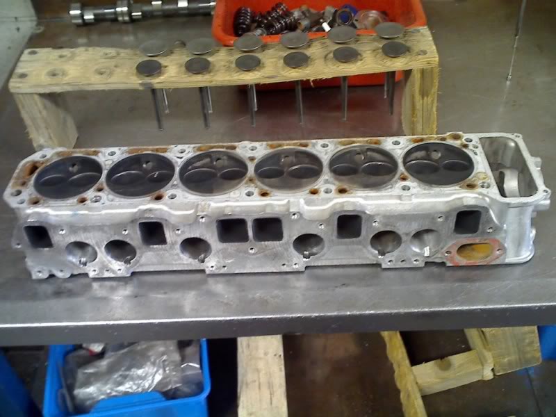
...where it is discovered that the valve seats are only 1/2mm (ie the valve seat only "seals" to the valve thru a thin contact patch 1/2mm wide). Tony said that was way too thin for longevity on the road, and is more evidence that this was a purpose built race head.
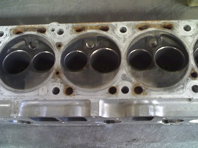
The head is bead blasted to clean it up.
Inpet ports are reshaped, you can see the valve guide boss has been trimmed down in size and made into a more streamlined shape. Also the surface finish of the inlet ports was deemed too smooth by Tony, and hence he roughed up the surface a bit to prevent fuel pooling on the port walls. One of the inlet ports had broken thru to water jacket by the head porter in Japan, and the hole was filled with 2 pack metal putty. It was holding ok, but Tony blasted it out, drilled out the hole and filled it properly with Devcon. He also said that the short turns (whatever they are!) were lumpy and ridged, so they're now smoothed and reshaped for better low-rpm flow.
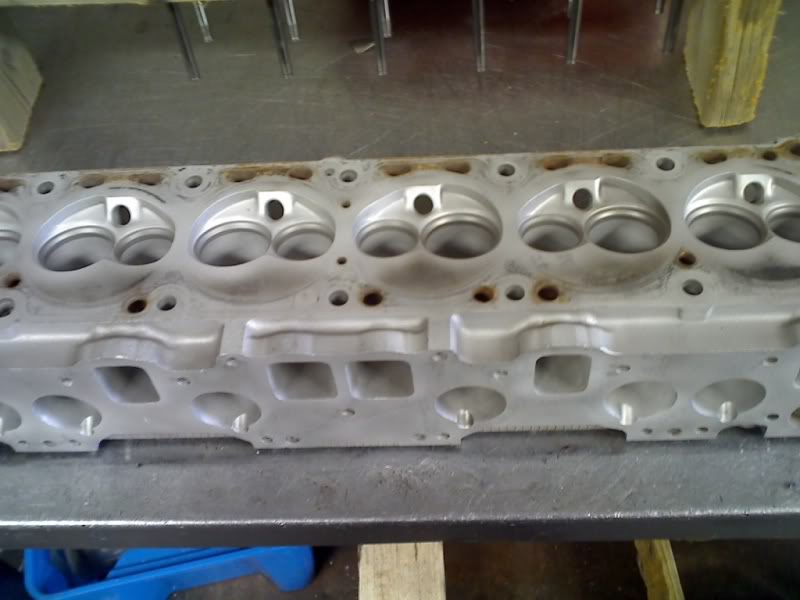
Exhaust ports refinished too.
Almost the finished product....
...combustion chambers were opened up a little bit to unshroud and expose the valves, the valve were also not concentric in the seats, so he's recut them to be central, and also remachined them to widen the valve seat from the thin 1/2mm to more like 1mm.
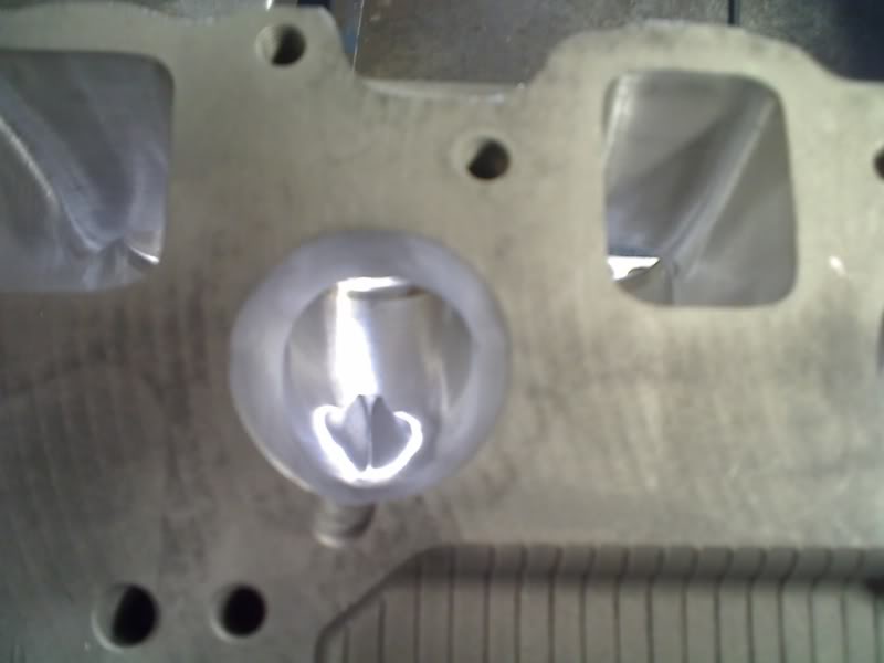
The finished ports.
Now that the head was finished, he put it on a flowbench and measured the flow at various different valve openings.
In the end, it was a really interesting exercise (even if some of it went completely over my head)  The verdict on my head was that whoever ported it in Japan set it up for max flow, max rpm and a very high compression ratio that would have required racing fuel. So Tony's main objective was to reduce the compression ratio, and try to boost flow at small-valve lifts, which will improve cylinder filling at low and mid range rpm. His final conclusion was that he would have liked to have more flow at small valve openings, but that the final result was pretty close to what he was aiming for.
What I learned, was that the devil's in a million little details, and while some "macro" parameters were too big for Tony's liking, he massaged things like the angle of the chamfer on the valves, the radius on the ports as they made a downward turn into the valve (he called this the "short turn") and probably a million other things he didn't tell me about I also learned that the "headline" figures aren't the be-all and end-all. And all of the little details have to go together, like how the valve stem lengths have to be machined to allow the rockers to sit at the optimum contact patch against the cam
I would say that there are a million little assumptions that a pro builder will make as he puts the engine together for you, and for better or worse, you should trust his judgment TBH, I'm sure that if I had the same conversation with the builder in Japan, he would make a prettu convincing argument for what he did too 
And here are the conversations that followed.
Got stuck in & found a few issues, nothing tragic tho.
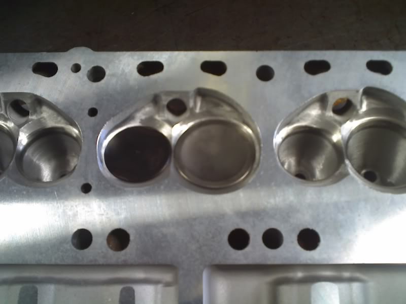
The intake seats I had just intended to touch up & widen a bit - but several were not concentric with the valve guides, so I made the decision to re-cut them as well & while it was on the seat machine I re-cut the valve reliefs for better low lift flow & to unshroud the intake valves a bit more.
The seats have been set up to flow well at high lift, sacrificing some low lift flow to do so - so the bowl sizes are really a little large, I'll have to reshape the bottom cut of the seat by hand to boost low lift flow as much as I can & rework the short turns a little with the same in mind.
Pretty much the same story on the exhausts, except the bowl sizes are better. I sunk the exhaust seats .025" & re-cut the relief as well.
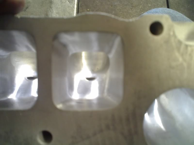
With the seats done & reliefs re-cut it's become obvious that the chambers are gonna need a bit more re-shaping than I anticipated.
The upside is that I'm gonna gain a fair bit more chamber volume than I thought & if the motor turns out to be stock stroke then a dish in the pistons may not be needed.
The only other issue that turned up was that the spot I thought had been welded turned ot to actually be 2-pac metal putty - discovered after bead blasting.
It seems to have been holding well tho, so not a major issue - I've blasted the old putty out & I'll re-fill the hole with devcon, let it cure good & proper & then pressure test to 40psi to be sure it'll be ok.
Welding is not really an option, the metal there is a bit too thin to weld reliably.
I've done 1 chamber to see how it's gonna come out - nice would be the answer.
The intake seats I had just intended to touch up & widen a bit - but several were not concentric with the valve guides, so I made the decision to re-cut them as well & while it was on the seat machine I re-cut the valve reliefs for better low lift flow & to unshroud the intake valves a bit more.
The seats have been set up to flow well at high lift, sacrificing some low lift flow to do so - so the bowl sizes are really a little large, I'll have to reshape the bottom cut of the seat by hand to boost low lift flow as much as I can & rework the short turns a little with the same in mind.
Pretty much the same story on the exhausts, except the bowl sizes are better. I sunk the exhaust seats .025" & re-cut the relief as well.
With the seats done & reliefs re-cut it's become obvious that the chambers are gonna need a bit more re-shaping than I anticipated.
The upside is that I'm gonna gain a fair bit more chamber volume than I thought & if the motor turns out to be stock stroke then a dish in the pistons may not be needed.
The only other issue that turned up was that the spot I thought had been welded turned ot to actually be 2-pac metal putty - discovered after bead blasting.
It seems to have been holding well tho, so not a major issue - I've blasted the old putty out & I'll re-fill the hole with devcon, let it cure good & proper & then pressure test to 40psi to be sure it'll be ok.
Welding is not really an option, the metal there is a bit too thin to weld reliably.
I've done 1 chamber to see how it's gonna come out - nice would be the answer.
Okey doke, all carbide cutter work is done, all port runners are final finished, 1 cylinders chamber, short turns & bowls done.
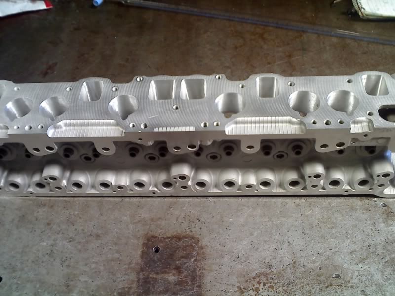
The area around the intake guide was not great - whoever ported the head did not remove the guides to do it, so there was a section that was a bit crappy. I bumped the guides down out the way & reshaped the guide boss a bit while I was in there with a grinder.
The area around the intake guide was not great - whoever ported the head did not remove the guides to do it, so there was a section that was a bit crappy. I bumped the guides down out the way & reshaped the guide boss a bit while I was in there with a grinder.
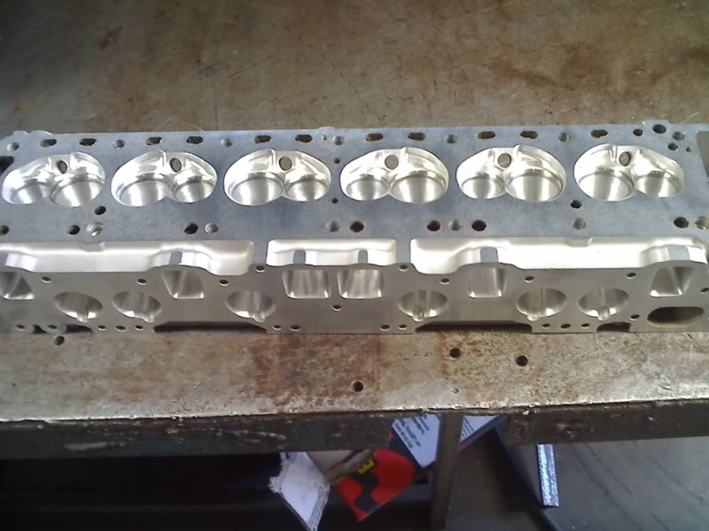
Porting finished, intake guides trimmed down a bit, head lightly milled on the top & bottom faces to true it.
Chamber volume has gone up to 35.5cc from 32.5cc.
With stock stroke & zero deck height that'll give approx 11.1-11.2:1, which is borderline with the 240/250 cam but would be ok with a good tune.
If the pistons are sitting a bit below the deck then setting deck height at .005" will give about 10.9-11:1, .010"deck height will give about 10.8:1.
So if it's stock stroke it won't need a dish in the pistons!
If its a stroker then comp with zero deck will be about 11.7:1 & will require a further 3cc dish in the slugs - which is quite small & very doable.
...where it is discovered that the valve seats are only 1/2mm (ie the valve seat only "seals" to the valve thru a thin contact patch 1/2mm wide). Tony said that was way too thin for longevity on the road, and is more evidence that this was a purpose built race head.
The head is bead blasted to clean it up.
Inpet ports are reshaped, you can see the valve guide boss has been trimmed down in size and made into a more streamlined shape. Also the surface finish of the inlet ports was deemed too smooth by Tony, and hence he roughed up the surface a bit to prevent fuel pooling on the port walls. One of the inlet ports had broken thru to water jacket by the head porter in Japan, and the hole was filled with 2 pack metal putty. It was holding ok, but Tony blasted it out, drilled out the hole and filled it properly with Devcon. He also said that the short turns (whatever they are!) were lumpy and ridged, so they're now smoothed and reshaped for better low-rpm flow.
Exhaust ports refinished too.
Almost the finished product....
...combustion chambers were opened up a little bit to unshroud and expose the valves, the valve were also not concentric in the seats, so he's recut them to be central, and also remachined them to widen the valve seat from the thin 1/2mm to more like 1mm.
The finished ports.
Now that the head was finished, he put it on a flowbench and measured the flow at various different valve openings.
Originally Posted by TK
Flow figures:
Intake
Lift Flow
.1 -- 58.8
.2 -- 113.8
.3 -- 153
.4 -- 187
.5 -- 215.8
.55 -- 223.6
.6 -- 226.9
Exhaust
.1 -- 43.2
.2 -- 80
.3 -- 102.1
.4 -- 128.8
.5 -- 144.1
.55 -- 151.5
.6 -- 156.6
in/ex ratio (%)
.1 -- 73
.2 -- 70
.3 -- 67
.4 -- 69
.5 -- 67
.55 -- 68
Average
in/ex ratio - 69%
Intake potential - 215.8cfm @ .5" lift = 331hp potential on a 6 cylinder.
Flow begins to taper off after .5-.55" lift - meaning that the head is pretty much ideally suited to a cam with around .5" lift, if the flow was to continue to rise quickly above that lift then it's a good bet the ports/bowls are too big & the seat angle wrong.
So, basically, it's even better than I thought it'd turn out, although I would have liked to see a little more exhaust flow - but that ain't gonna happen without larger exhaust valves, the bowls & ports are pretty much maxxed out. It would seem the cam guys know that datto's aren't great on the exhausts, that'd explain the big forward split on the cam 240 deg on the intake & 250 on the exhaust - that'll make up for the not ideal exhaust flow nicely. I was initially thinking the cam may have a bit too much ex duration, but as it turns out it'll be spot on.
Babs - if you can measure the intake runner length (from end of carb stacks to manifold face) I'll run it through engine analyser pro & get an idea of the power curve.
Off the top of my head methinks it'll do 260-280hp, should make at least 200rwhp.
Originally Posted by TK
Based on 38mm chokes in the webers, 12" total intake runner length, 1.5" primary headers:
I musta got something wrong, EAP is predicting 401hp @ 6500rpm & 389ft/lbs at 4500rpm.
I'll put some smaller chokes in the carb & restrict the exhaust a bit to try to get a realistic figure out of it.
Ok, with 35mm chokes in the carbs & a street type exhaust it's still showing 370hp @ 7000rpm & 372ft/lbs at 4000rpm.
On pump fuel, with full exhaust system.
Originally Posted by TK
Checked it again & again - can't find anything wrong with the sim, if anything the values I've plugged in are conservative.
Even the knock values EAP is spitting out indicate that it'll be 100% fine on pump 98.
Gonna be a strong motor.
Even the knock values EAP is spitting out indicate that it'll be 100% fine on pump 98.
Gonna be a strong motor.
Originally Posted by Babalouie
Ooh that's promising
Okies....inlet is 28.5cm from air horn to manifold face.
Carbs are 40DCOE with 32mm chokes (I woulda thought this would be the biggest restriction).
Zorst is a dual system, 43mm pipes. Headers are 6 into 2 (then it just goes dual, it never merges to 1) with 42mm primaries, 52mm secondaries.
BTW I think (got to take more time to measure it properly later) that deck height is negative 0.08mm.
Originally Posted by TK
Ok, with 32mm chokes etc she's still showing 345hp @ 6500rpm.
I had a chat with Peter Schaeffer coz I know he had a lot to do with dato's back in the day - I ran the combo past him & he said it'll make 300+hp on a bad day.
Stick a set of 45DCOE webers on it & it'll go 330-340hp without trying hard.
Any way you look at it the ****ing thing is gonna hammer.
I had a chat with Peter Schaeffer coz I know he had a lot to do with dato's back in the day - I ran the combo past him & he said it'll make 300+hp on a bad day.
Stick a set of 45DCOE webers on it & it'll go 330-340hp without trying hard.
Any way you look at it the ****ing thing is gonna hammer.
Originally Posted by TK
If you stick a set of 45's with 40mm chokes on it, assume it's a 3.1L stroker & crank compression to 11.5 (which it would be if it was 3.1L):
Knock index is still fine, pump 98 no probs.
400hp @ 7000rpm - it'd do 360-370 in real life & should crank out 270-280hp atw.
Even with the big carbs & 7000rpm on board intake velocity tops out at mach .44 - which is real nice, damn near perfect actually.
I can't get those 45's - the guy sold them a coupla weeks ago.
But this motor will be begging for more carb - 45's would round out the engine real nice.
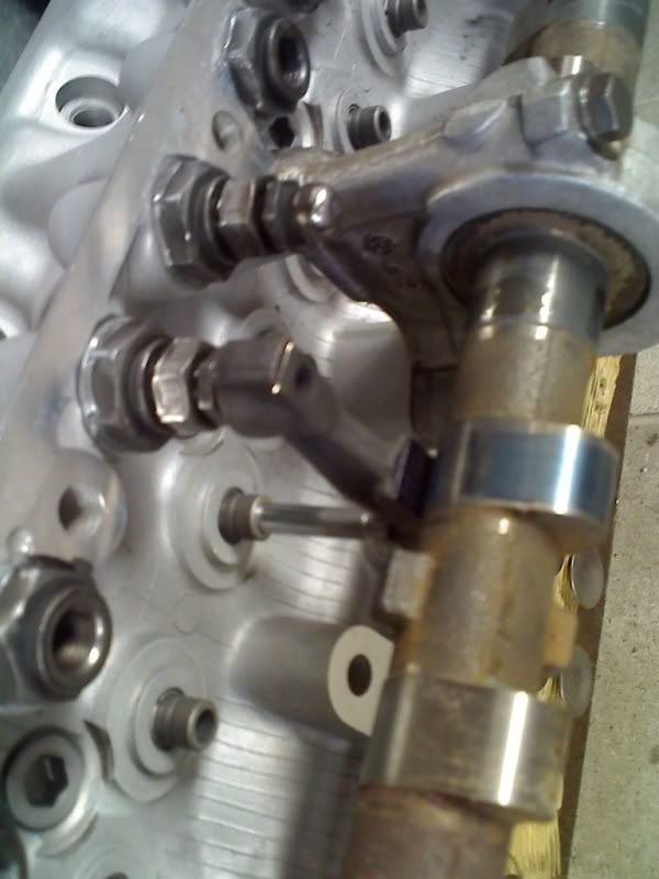
Ok, everything washed up & laid out for some final checks.
I worked out how low I could grind the valve tips before lash cap clearance became an issue - I've left .020" clearance so the valves can be tipped again in the future if need be & ground them all to equal height within .002" so the rocker geometry is consistant between cylinders.
The valve tips still sit about 1.75mm higher than stock - so I was a little concerned about rocker geometry & decided to to a quick dummy up & check it.
Wipe pattern is nice & central & there is still plenty of adjustment left in the rocker posts = win.
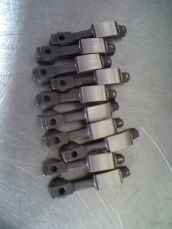
Pics:
Refaced rocker arms refaced on both the cam contact pad & lash cap contact pad):
Th only potential hiccup left is valve spring installed height & seat pressure - as the valves have been sunk a total of almost 2.5mm into the chamber face the collet groove heights are around 2.5mm higher than stock, so spring installed height is gonna be up the ****.
I'll have to put 3 sets of spring bases in to get it close to right & will check seat pressure from there - worst case I may have to make up a set of spring spacers.
Once I've got some retainers (no one wil admit to having any - everyone did the same as me & threw all the old datto stuff out a coupla years ago, bugger) I can also sus out what the old springs will give in the way of seat pressure & decide which way to go.
I just had a thought - I may be able to machine down the old retainers to allow the use of a stock lash cap & re-use the old springs - will go check.
I worked out how low I could grind the valve tips before lash cap clearance became an issue - I've left .020" clearance so the valves can be tipped again in the future if need be & ground them all to equal height within .002" so the rocker geometry is consistant between cylinders.
The valve tips still sit about 1.75mm higher than stock - so I was a little concerned about rocker geometry & decided to to a quick dummy up & check it.
Wipe pattern is nice & central & there is still plenty of adjustment left in the rocker posts = win.
Pics:
Refaced rocker arms refaced on both the cam contact pad & lash cap contact pad):
Th only potential hiccup left is valve spring installed height & seat pressure - as the valves have been sunk a total of almost 2.5mm into the chamber face the collet groove heights are around 2.5mm higher than stock, so spring installed height is gonna be up the ****.
I'll have to put 3 sets of spring bases in to get it close to right & will check seat pressure from there - worst case I may have to make up a set of spring spacers.
Once I've got some retainers (no one wil admit to having any - everyone did the same as me & threw all the old datto stuff out a coupla years ago, bugger) I can also sus out what the old springs will give in the way of seat pressure & decide which way to go.
I just had a thought - I may be able to machine down the old retainers to allow the use of a stock lash cap & re-use the old springs - will go check.
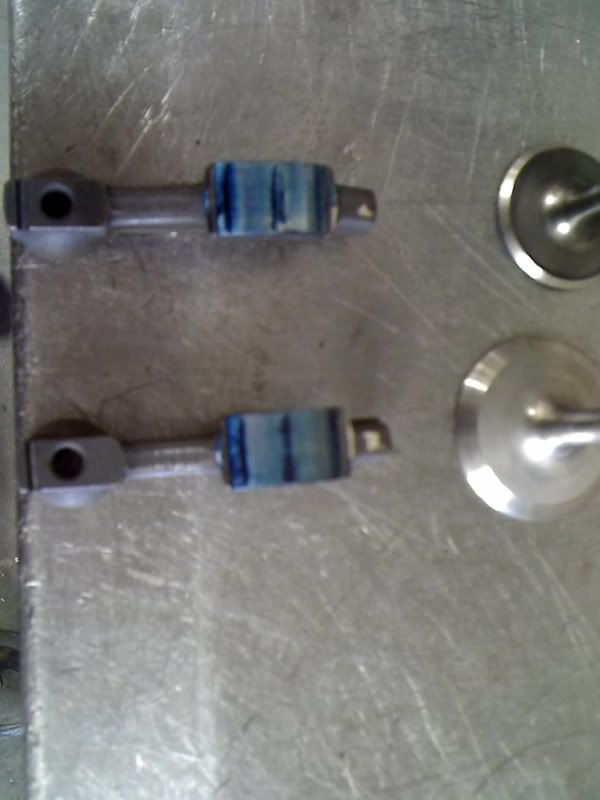
Winnar!
With an old retainer machined flat on top (which still gives plenty of meat to retain a stock lash cap) it damn near fits, a little clearancing of the rocker arms & it does fit.
Rocker geometry is unchanged, old springs test up fine & will work with the higher installed height that is due to the valve seats being sunk so far.
There is still enough adjustment (not heaps, but enough).
The verdict on my head was that whoever ported it in Japan set it up for max flow, max rpm and a very high compression ratio that would have required racing fuel. So Tony's main objective was to reduce the compression ratio, and try to boost flow at small-valve lifts, which will improve cylinder filling at low and mid range rpm. His final conclusion was that he would have liked to have more flow at small valve openings, but that the final result was pretty close to what he was aiming for.What I learned, was that the devil's in a million little details, and while some "macro" parameters were too big for Tony's liking, he massaged things like the angle of the chamfer on the valves, the radius on the ports as they made a downward turn into the valve (he called this the "short turn") and probably a million other things he didn't tell me about
I also learned that the "headline" figures aren't the be-all and end-all. And all of the little details have to go together, like how the valve stem lengths have to be machined to allow the rockers to sit at the optimum contact patch against the cam I would say that there are a million little assumptions that a pro builder will make as he puts the engine together for you, and for better or worse, you should trust his judgment
TBH, I'm sure that if I had the same conversation with the builder in Japan, he would make a prettu convincing argument for what he did too
10-11-2012, 06:17 AM
#155
Drifting
Thread Starter
As said, I'm just prodding and learning. Thank you for bearing with my learning curve - appreciated.
I've researched all over and was becoming more and more sceptical.
As it turns out we had changed cam specification to a custom designed cam for the job that has a higher lift than the RSR cams we had previously decided on. We're looking into a plenum...
As a side note, we're still on budget.
FWIW, Frank, I went through a similar exercise on the engine in my other car.
What I learned, was that the devil's in a million little details, and while some "macro" parameters were too big for Tony's liking, he massaged things like the angle of the chamfer on the valves, the radius on the ports as they made a downward turn into the valve (he called this the "short turn") and probably a million other things he didn't tell me about I also learned that the "headline" figures aren't the be-all and end-all. And all of the little details have to go together, like how the valve stem lengths have to be machined to allow the rockers to sit at the optimum contact patch against the cam
I would say that there are a million little assumptions that a pro builder will make as he puts the engine together for you, and for better or worse, you should trust his judgment TBH, I'm sure that if I had the same conversation with the builder in Japan, he would make a prettu convincing argument for what he did too
What I learned, was that the devil's in a million little details, and while some "macro" parameters were too big for Tony's liking, he massaged things like the angle of the chamfer on the valves, the radius on the ports as they made a downward turn into the valve (he called this the "short turn") and probably a million other things he didn't tell me about
I also learned that the "headline" figures aren't the be-all and end-all. And all of the little details have to go together, like how the valve stem lengths have to be machined to allow the rockers to sit at the optimum contact patch against the cam I would say that there are a million little assumptions that a pro builder will make as he puts the engine together for you, and for better or worse, you should trust his judgment
TBH, I'm sure that if I had the same conversation with the builder in Japan, he would make a prettu convincing argument for what he did too  10-11-2012, 06:51 AM
#156

The verdict on my head was that whoever ported it in Japan set it up for max flow, max rpm and a very high compression ratio that would have required racing fuel. So Tony's main objective was to reduce the compression ratio, and try to boost flow at small-valve lifts, which will improve cylinder filling at low and mid range rpm. His final conclusion was that he would have liked to have more flow at small valve openings, but that the final result was pretty close to what he was aiming for.
Some elements in the way your head was reworked in Japan show this as well. For instance valve seats, thin is good...therefore thinner must be better? WRONG! The 0.5mm seats from Japan both severely hurt flow and longevity. Extensive flow bench testing shows 1.25-1.5mm to be about optimal.
On the subject of boosting low lift flow as your tuner has rightly aimed for, think of the time a valve spends without being at full lift (upwards cycle AND downwards cycle) and anyone will see how important this is....especially on road/endurance cams with gentle acceleration ramps.
Anyway, here's a nice article on the subject http://www.stockcarracing.com/techar...s/viewall.html
10-11-2012, 10:21 AM
#157
Addict
Rennlist
Site Sponsor
Rennlist
Site Sponsor
Judging engine performance purely on a notional intake flow ability is obviously a huge over-simplification, but your engine guy probably knows that but decided to save you a headache. Big ports make big flow numbers and on the back of a massive "tuning" industry that has been built on telling everyone that bigger is better, but the concept is fundamentally wrong. Hence please don't get hooked on following the same line of thinking, all you will end up doing is losing torque at the expense of an engine that wants to make power at an engine speed above its rpm limit.
10-12-2012, 02:49 PM
#158
Addict
Rennlist
Site Sponsor
Rennlist
Site Sponsor
As promised, here is the dyno graph of the 993C4S Varioram which is fitted with a 3.75 litre "RS" engine running cup camshafts, stock heat exchangers and cat bypasses. The car came in to convert from Motronic to Motec on the basis of getting it to behave politely in traffic and not stall. We have now achieved this goal and as a slight bonus have found a few more Nm through the midrange with a little more top end power.
As you can clearly see, the Varioram system produces a very flat torque curve from 3000rpm upwards but rolls off the torque at the top end, hence my comments about the VR performing like a supercharger - which technically is exactly what the VR is doing, only using intake resonance to increase cylinder charge pressure rather than a mechanical pump. Note that the useable torque band is around 3000rpm wide, from roughly 3250rpm to 6250rpm.
The second dyno graph is a 9m 3.75 litre Clubsport race engine. This engine runs 9m billet heads and the 9m intake system which has been specifically tuned for high intake velocity which uses intake inertia to supercharge the cylinders. Note that the useable torque band is now 3500rpm wide from 4000rpm to 7500rpm. The engine made over 400hp and when installed in a 964RS the car would match a GT3RS on a straight line drag.
10-16-2012, 08:44 PM
#159
Three Wheelin'
Hey Frank, I wonder if Nick would share the specs on the exhaust design (size and length of primaries mainly), and also the custom cam spec (lift/duration/timing/overlap)?
This is the book I was talking about (BTW I got my Bells confused, this isn't Corky Bell - Corky's a different tuning guru altogether)
Anyway that book gives some rules of thumb on valve sizes based on cylinder size (625cc in your case) and port sizing based on value size (with examples from lots of performance engines) and Nick's figures don't look bonkers on that basis. A G Bell talks about the danger of going too large and blindly looking for high flow-bench numbers, and give some examples of the pitfalls.
Also the exhaust side of the equation clearly has an important effect on the mid range torque. If you tune the cam overlap and the exhaust pressure waves to coincide you can get a similar "supercharging" (ie >100% VE) effect Colin describes buy sucking air mix into the cylinder from the "other side". Then you can use unequal length primaries to tune the effect to different RPM on different cylinders spreading the torque you win nicely across the rev range. Well, that's the theory, all you need is a lifetime of experience to apply it correctly.
Colin clearly has carefully developed a configuration that works well, Nick may well have a different configuration that also works well, there's more than one way to skin a cat.
10-17-2012, 10:06 AM
#161
Addict
Rennlist
Site Sponsor
Rennlist
Site Sponsor
Also the exhaust side of the equation clearly has an important effect on the mid range torque. If you tune the cam overlap and the exhaust pressure waves to coincide you can get a similar "supercharging" (ie >100% VE) effect Colin describes buy sucking air mix into the cylinder from the "other side". Then you can use unequal length primaries to tune the effect to different RPM on different cylinders spreading the torque you win nicely across the rev range. Well, that's the theory, all you need is a lifetime of experience to apply it correctly.
Exactly. I am the first to admit that it is never to late to learn new methods for making an engine work and as a result it would be grossly unfair of me to critisise an alternative alternative (to 9m) approach of enhancing the performance of an engine.
10-17-2012, 11:05 AM
#163
I reckon so. We seem to have had quite a few of these accounts in the past few weeks - always seem to have 5s in their usernames. I just use the Report Post link on the left and hope that someone is dealing with them!
Spam post has now been removed. We're not referring to any real posts above as being spam.
Spam post has now been removed. We're not referring to any real posts above as being spam.
Last edited by ScottR; 10-17-2012 at 06:05 PM. Reason: Spam post removed
10-17-2012, 03:07 PM
#164
Drifting
Thread Starter
Hey Frank, I wonder if Nick would share the specs on the exhaust design (size and length of primaries mainly), and also the custom cam spec (lift/duration/timing/overlap)?
This is the book I was talking about (BTW I got my Bells confused, this isn't Corky Bell - Corky's a different tuning guru altogether)
http://www.amazon.co.uk/Four-stroke-...dp_ob_title_bk
Anyway that book gives some rules of thumb on valve sizes based on cylinder size (625cc in your case) and port sizing based on value size (with examples from lots of performance engines) and Nick's figures don't look bonkers on that basis. A G Bell talks about the danger of going too large and blindly looking for high flow-bench numbers, and give some examples of the pitfalls.
Also the exhaust side of the equation clearly has an important effect on the mid range torque. If you tune the cam overlap and the exhaust pressure waves to coincide you can get a similar "supercharging" (ie >100% VE) effect Colin describes buy sucking air mix into the cylinder from the "other side". Then you can use unequal length primaries to tune the effect to different RPM on different cylinders spreading the torque you win nicely across the rev range. Well, that's the theory, all you need is a lifetime of experience to apply it correctly.
Colin clearly has carefully developed a configuration that works well, Nick may well have a different configuration that also works well, there's more than one way to skin a cat.
10-22-2012, 09:05 AM
#165
Drifting
Thread Starter
UPDATE 7.5
Here are some pics.
* The heads are now complete 'in rough state' and will be all sparkly soon.
* The towers are all good to go.
* ITBs, 3.0 RSR flat-slides were digitally scanned to create a 3D computer model, then modifications were made for this application. Then the data is input and the machining begins.
* Trumpet length I believe will be around the same size as the 3.0 RSR items but this may change as Nick is designing a carbon fibre plenum to go over the top. Which should give us good performance and slightly lower dbs.
* The engine I'm told should be in long form by the end of the week
* The exhaust will be from the headers and will then cross creating a vacuum of sorts before entering a single silencer. Although the silencer configuration may still change...
* Cams, sadly but understandably I can't divulge the spec's

We had yet another long conversation about how I'll be using the car, where the performance should be - how torque will be delivered and where. I'm feeling confident.
Time scale. We're still dead on budget, but running behind schedule as machining the ITBs is taking time.
Last edited by Porsche964FP; 10-22-2012 at 09:43 AM.