
My Engine Rebuild
 03-11-2009, 11:31 PM
#16
I don't think I could handle the stress of having that thing apart in my shed. I'd lie awake at night worrying how I will remember how to get it all back together. Kudos to you my friend!


 03-12-2009, 02:14 AM
#18
Racer
Join Date: Dec 2008
Posts: 453
Likes: 0
Received 0 Likes
on
0 Posts
Looks like you're doing a great job so far. What are you using as a reference guide and is it as complete as you need it to be? I mean, anything missing in the manual? Also, how much is the outlay in parts? I always wondered how much a do-it-yourselfer could get away with.  Good luck!
Good luck!
03-12-2009, 11:02 AM
#20
Professor of Pending Projects
Rennlist Member
Rennlist Member
03-12-2009, 11:24 AM
#21
Instructor
Join Date: Aug 2006
Location: Denver, Colorado
Posts: 180
Likes: 0
Received 0 Likes
on
0 Posts
Epic thread. I love the pics - the blowup diagrams we see regularly never do the real thing justice. Best of luck, and may Mr. Murphy keep his sorry paws away from the project!
03-12-2009, 08:02 PM
#22
Rennlist Member
Thread Starter
Join Date: Sep 2006
Location: Welwyn Garden City, Herts England
Posts: 121
Likes: 0
Received 0 Likes
on
0 Posts
Once again thanks for the positive comments. I am not a qualified engineer or mechanic, but a keen fiddler (if that�s not rude). I have used the following reference material along with many hours searching various internet forums, talking to people and trying to work out potential problems in advance. Planning, cleanliness and not being in a rush helps. There is no point taking a short cut, it will bit you back later on.
How to rebuild and Modify Porsche 911 engines 1965 to 1989, by Wayne Dempsey. Though not specific to the 964 it covers the general principals behind the rebuild with lots of good photos and text which you can follow and adapt as necessary.
Porsche Workshop Manuel, on CD. I have two copies of this which vary slightly with what pages have been missed out. It gives a over view on some items, but others are missing completely. I imagine the proper paper copies are complete enough to work from solely.
Porsche Carrera 964 Technical Data Without Guesswork, by Bentley. Most of the drawings and text is taken straight from the factory manual, but is all in an easy to find format. Some torque valves are missed out, such as the Thrust plate to cam carrier 10Nm. Mine has scribbled notes all over it now.
This could all go horrifically wrong and require me to pull the engine apart again, or worse still give it to someone to sort out for me. There have been a few things I have done which I was not happy about. I stripped what ever it was back down and did it all again until I was happy, this is very frustrating and you begin to doubt your sanity at some points. I have had to buy several gaskets and fasteners again as I had doubts in my mind about how something had been done, but least I now have a clear conscious about it.
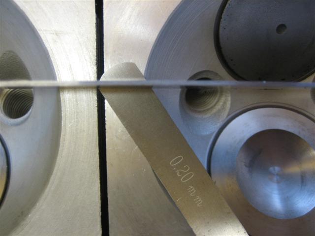
Disaster number two and three then appears within a day of each other. I am not going to go into it fully as it makes me mad every time I think back about it, but just to say one head was cracked despite being checked, given the OK then rebuilt by a supposed specialist machine shop. I felt that the other five heads that had been machined incorrectly and would cause me sealing and running issues. In essence the newly machined faces were not square with the cam face and up to 0.3mm too much material had been removed from them. I spent about two months of weekends, checking, measuring compression ratios, dry building the engine and measuring valve to piston contact.
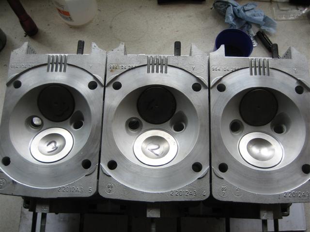
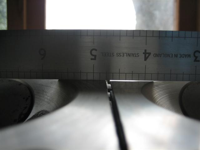
Max differance between heads should be 0.02mm, not 0.2mm!!!!!
This culminated in a post on this forum, which introduced me to Colin Belton again at Ninemeister.
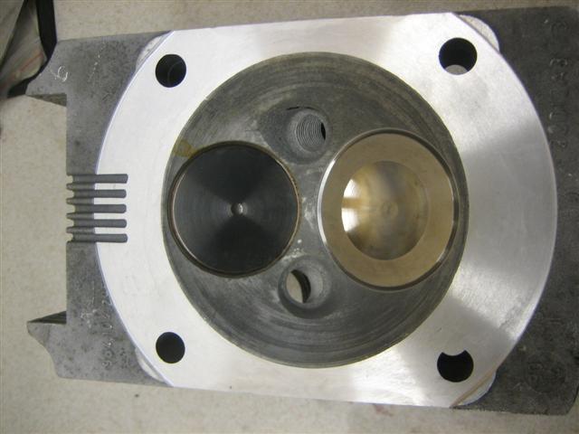
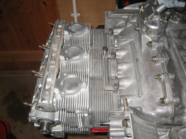
Luckily I had managed to buy a spare set of blank heads which Colin rebuilt for me as follows:
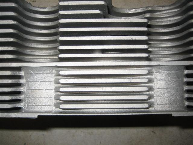
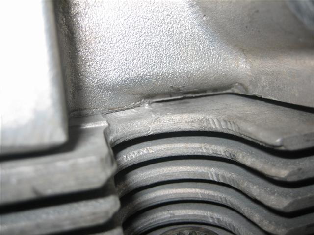
Welded lower fins.
Machined to suite later style cylinders.
Very slightly over machined to increase compression ratio and improve squish.
New exhaust and intake guides.
Three angle cuts to the valve seats to improve flow and increase valve sealing.
I did check Colins work when I got it back to my shed and could find nothing amiss what so ever. Thanks very much Colin.
The heads as collected from Colin on Christmas Eve!
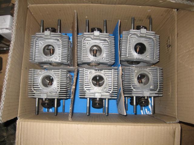
Welded bottom fins to prevent the lower fin distorting following machnining. compare this with the paper thin fin of my first heads.
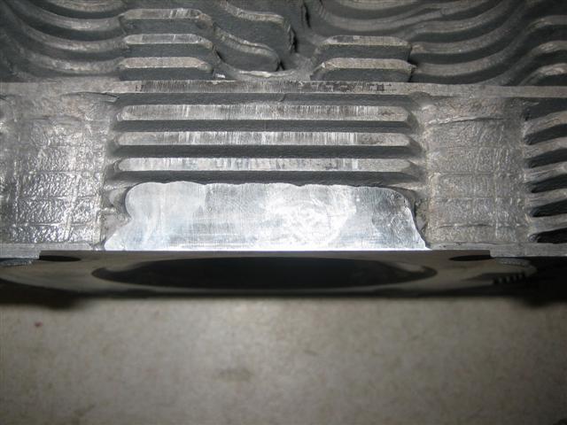
Nice and clean.
How to rebuild and Modify Porsche 911 engines 1965 to 1989, by Wayne Dempsey. Though not specific to the 964 it covers the general principals behind the rebuild with lots of good photos and text which you can follow and adapt as necessary.
Porsche Workshop Manuel, on CD. I have two copies of this which vary slightly with what pages have been missed out. It gives a over view on some items, but others are missing completely. I imagine the proper paper copies are complete enough to work from solely.
Porsche Carrera 964 Technical Data Without Guesswork, by Bentley. Most of the drawings and text is taken straight from the factory manual, but is all in an easy to find format. Some torque valves are missed out, such as the Thrust plate to cam carrier 10Nm. Mine has scribbled notes all over it now.
This could all go horrifically wrong and require me to pull the engine apart again, or worse still give it to someone to sort out for me. There have been a few things I have done which I was not happy about. I stripped what ever it was back down and did it all again until I was happy, this is very frustrating and you begin to doubt your sanity at some points. I have had to buy several gaskets and fasteners again as I had doubts in my mind about how something had been done, but least I now have a clear conscious about it.
Disaster number two and three then appears within a day of each other. I am not going to go into it fully as it makes me mad every time I think back about it, but just to say one head was cracked despite being checked, given the OK then rebuilt by a supposed specialist machine shop. I felt that the other five heads that had been machined incorrectly and would cause me sealing and running issues. In essence the newly machined faces were not square with the cam face and up to 0.3mm too much material had been removed from them. I spent about two months of weekends, checking, measuring compression ratios, dry building the engine and measuring valve to piston contact.
Max differance between heads should be 0.02mm, not 0.2mm!!!!!
This culminated in a post on this forum, which introduced me to Colin Belton again at Ninemeister.
Luckily I had managed to buy a spare set of blank heads which Colin rebuilt for me as follows:
Welded lower fins.
Machined to suite later style cylinders.
Very slightly over machined to increase compression ratio and improve squish.
New exhaust and intake guides.
Three angle cuts to the valve seats to improve flow and increase valve sealing.
I did check Colins work when I got it back to my shed and could find nothing amiss what so ever. Thanks very much Colin.
The heads as collected from Colin on Christmas Eve!
Welded bottom fins to prevent the lower fin distorting following machnining. compare this with the paper thin fin of my first heads.
Nice and clean.
03-12-2009, 11:58 PM
#24
Racer
Join Date: Dec 2008
Posts: 453
Likes: 0
Received 0 Likes
on
0 Posts
mrmoots, what you are doing is gaining experience, and in gaining experience you WILL make mistakes. That's just how it works, no other way around it. So don't be too hard on yourself.
I hear that the trickiest part to building this style engine is setting up the timing. Can't wait to see your report. Thanks so much for taking the time to post all of this great info!!
I hear that the trickiest part to building this style engine is setting up the timing. Can't wait to see your report. Thanks so much for taking the time to post all of this great info!!
03-13-2009, 07:17 PM
#25
Rennlist Member
Thread Starter
Join Date: Sep 2006
Location: Welwyn Garden City, Herts England
Posts: 121
Likes: 0
Received 0 Likes
on
0 Posts
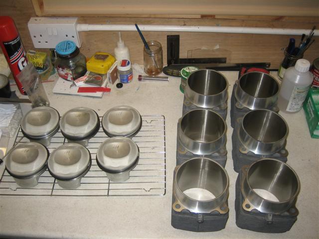
One thing I was disappointed about with the Mahle pistons was the difference in weight. Up to 5grams. I believe Porsche specify a tolerance up to 9grms, but I wanted to make the engine as smooth as possible. When the heads were up with Colin at Ninemeister I took the pistons with me and he lightened them so they are all within 1gram of each other. In Wayne�s book he mentions about removing material from the bore of the wrist pin. I spoke to Colin about this who advised removal from the piston is better. The wrist pins were all bang on 138grams each.
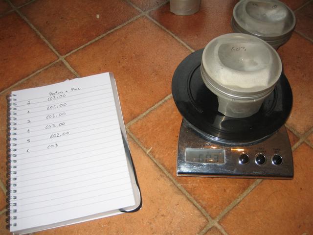
The Mahle set comes with rings. I dissembled everything, cleaned the pistons, cleaned the rings and cylinders with Isopropyl alcohol then put the rings back on.
The Mahle set comes with rings. I dissembled everything, cleaned the pistons, cleaned the rings and cylinders with Isopropyl alcohol then put the rings back on.
03-13-2009, 07:38 PM
#26
Rennlist Member
Thread Starter
Join Date: Sep 2006
Location: Welwyn Garden City, Herts England
Posts: 121
Likes: 0
Received 0 Likes
on
0 Posts
There appears to be two schools of thought to mount the pistons. Either mount the pistons onto the rods, then fit the cylinders over the top, which I felt was a little tricky. Or the option I chose, mount the pistons into the cylinder, then month the whole assembly onto the rods. Either way you need to get the spring clip into the pistons to hole the wrist pin into position.
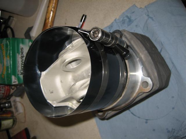
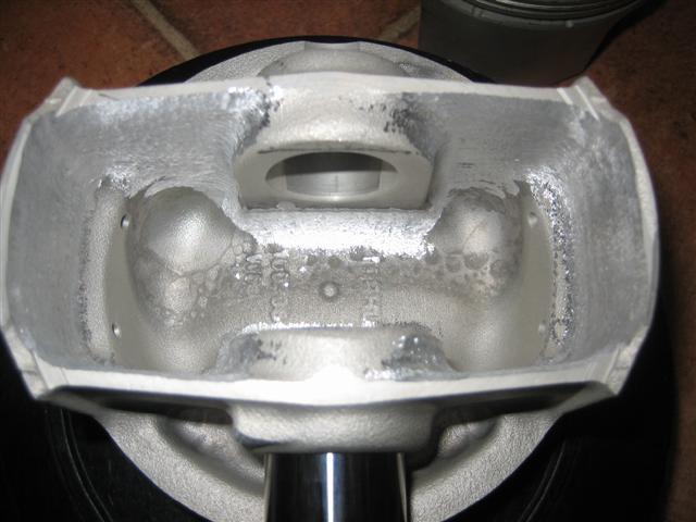
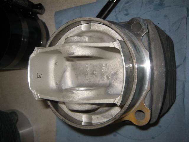
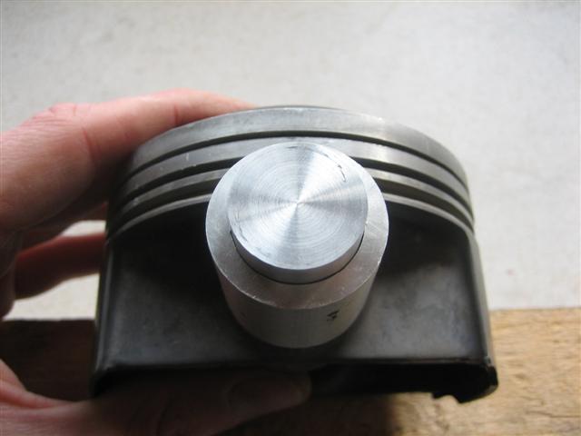
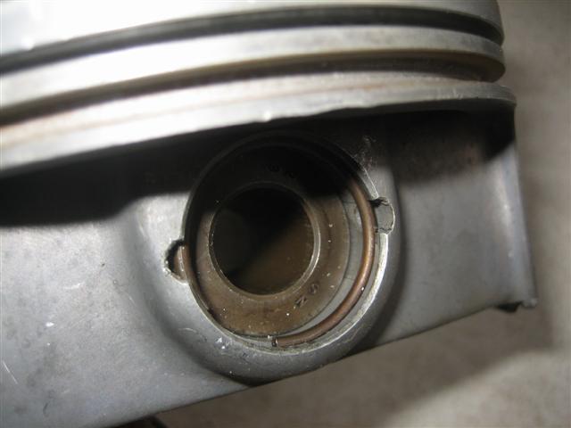
The "E" in pen tells me which way the piston orientation is. The lugs on the base of the piston are slightly a difference shape/mass. From what I understand this is to counteract twisting/turning at high RPM as the pistons are flung out from the case.
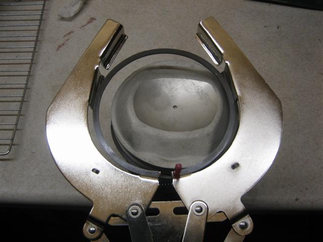
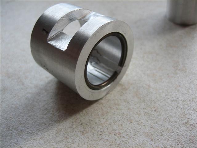
To set the spring clips Porsche specify a special tool. I messed about with an old wrist pin and a bit of alloy tubing with mixed results. In the end I sheeted over the engine, got my little model engineering lath out again and made an alloy copy of the Porsche tool. It worked a treat with reliable positive locations each time.
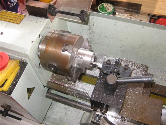
The Finished Tool
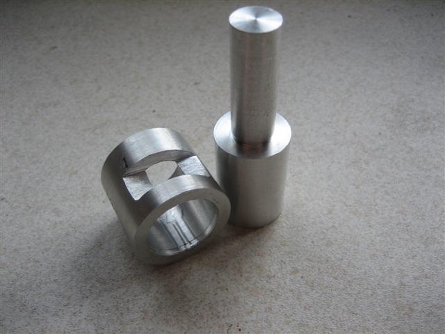
In reality it looks simple, but working overhand on the engine and not letting the bottom piston ring come out from the cylinder is not easy. This is an old piston I used as a test
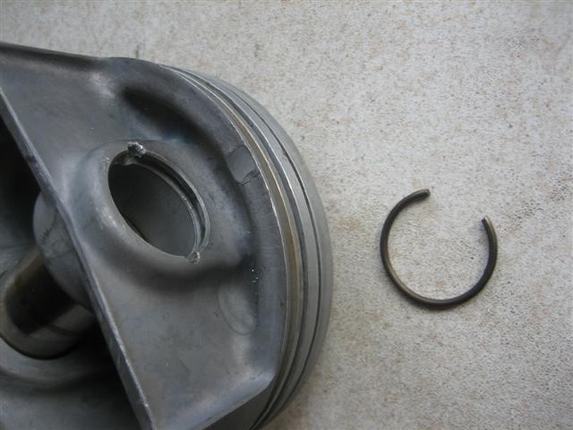
Squeeze and get the spring clip into the body of the tool
With the wide end, push the clip to the end of the body, do this on a hard flat surface, or the clip is off into the distance.
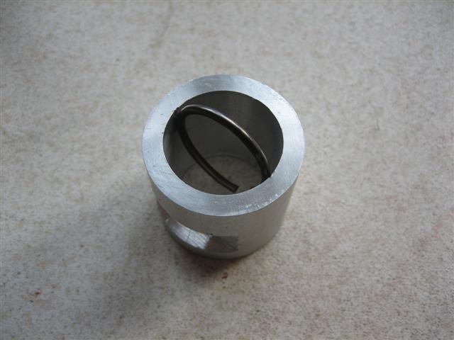
I cut a groove into the body of the tool to locate and hold the ring in place.
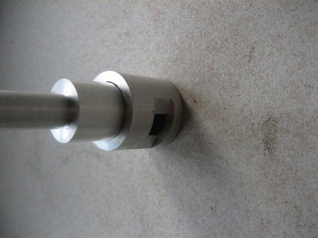
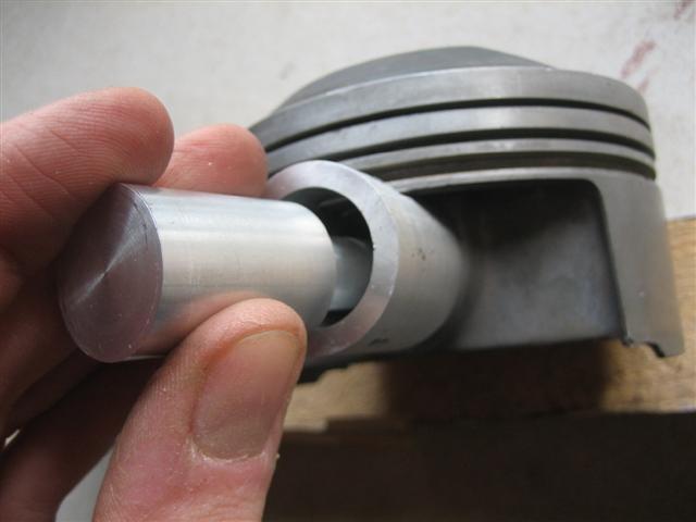
You have to offer up the body to the piston and locate roughly
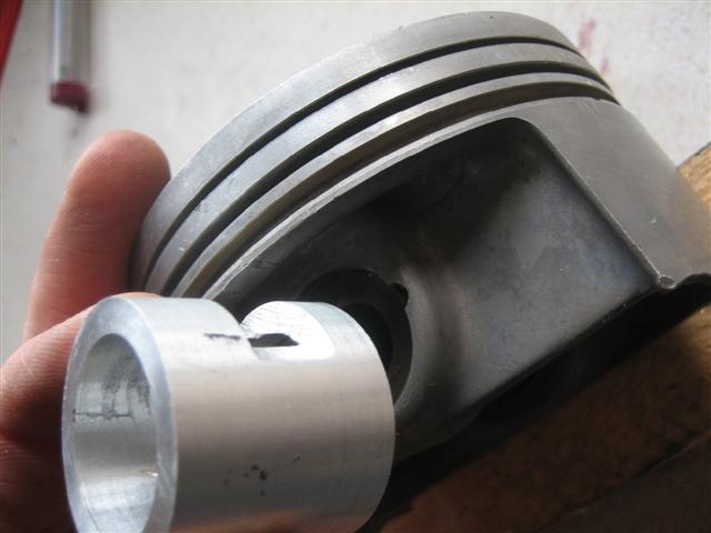
Spin the tool round and insert the narrow end. This locates in the bore of the wrist pin and centralises the entire assembly.
A swift tap with a hammer, or even just hand force
And hey presto, one seated spring clip.
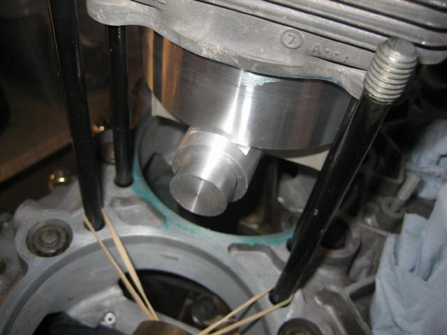
In use on the engine.
The "E" in pen tells me which way the piston orientation is. The lugs on the base of the piston are slightly a difference shape/mass. From what I understand this is to counteract twisting/turning at high RPM as the pistons are flung out from the case.
To set the spring clips Porsche specify a special tool. I messed about with an old wrist pin and a bit of alloy tubing with mixed results. In the end I sheeted over the engine, got my little model engineering lath out again and made an alloy copy of the Porsche tool. It worked a treat with reliable positive locations each time.
The Finished Tool
In reality it looks simple, but working overhand on the engine and not letting the bottom piston ring come out from the cylinder is not easy. This is an old piston I used as a test
Squeeze and get the spring clip into the body of the tool
With the wide end, push the clip to the end of the body, do this on a hard flat surface, or the clip is off into the distance.
I cut a groove into the body of the tool to locate and hold the ring in place.
You have to offer up the body to the piston and locate roughly
Spin the tool round and insert the narrow end. This locates in the bore of the wrist pin and centralises the entire assembly.
A swift tap with a hammer, or even just hand force
And hey presto, one seated spring clip.
In use on the engine.
03-13-2009, 07:56 PM
#27
Rennlist Member
Thread Starter
Join Date: Sep 2006
Location: Welwyn Garden City, Herts England
Posts: 121
Likes: 0
Received 0 Likes
on
0 Posts
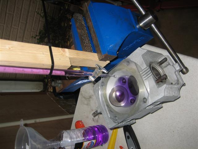
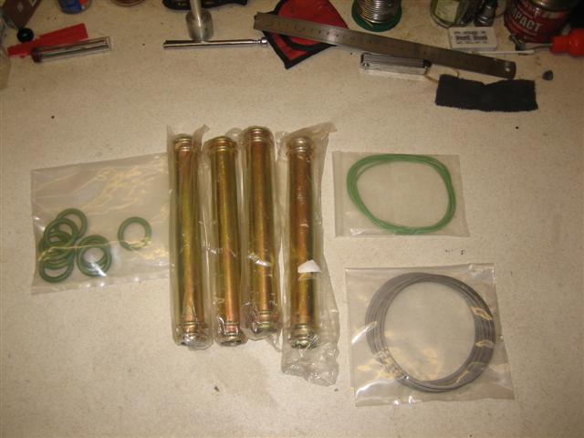
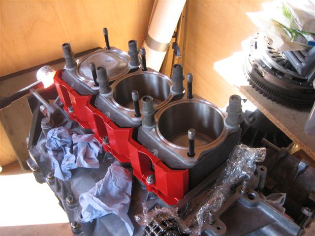
New Viton base �O� rings (from the Wrightwood Racing gasket set), new return tubes and new Graphite head rings, again from the Wrightwood set.
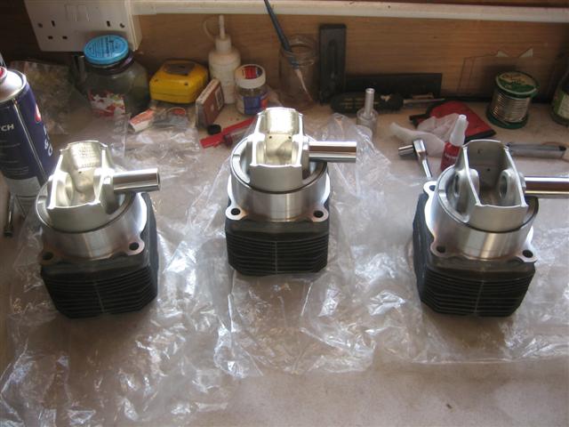
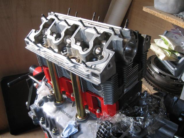
Here goes, the first three cylinder assemblies.
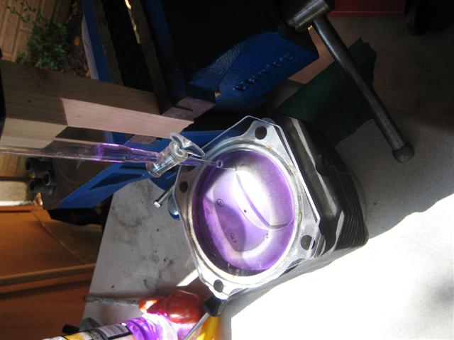
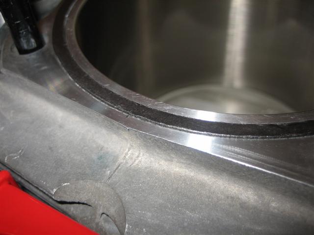
I applied a very light bead of Curil T to the recess in the cylinder base, then slid the "O" ring into position.
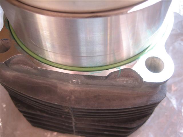
I then applied a light coating to the case mating surface. This looks thicker in the photo, I think the flash brings out the green pigment. The blue marker on the through bolts was to remind me which ones I had "O" ringed up earlier in the rebuild
One by one they go on. On each piston I had mounted the right hand spring clip when on the bench. That way I only needed to locate the wrist pin into the rod, push home, then fit the second sping clip with my home made tool.
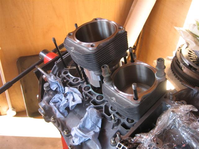
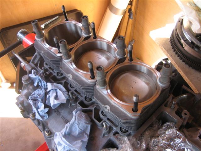
Thats the three on. Cylinders one to three.
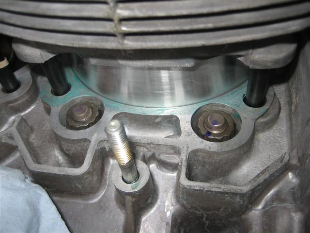
I located the cylinders with double head bolts. I put a nylon washer between the lower bolts and the cylinders to prevent damage. Only done finger tight anyway. The air sheilds had been sand blasted and powdercoated bright red. The cam covers and fan are all matching, pimpy or what!
Here goes, the first three cylinder assemblies.
I applied a very light bead of Curil T to the recess in the cylinder base, then slid the "O" ring into position.
I then applied a light coating to the case mating surface. This looks thicker in the photo, I think the flash brings out the green pigment. The blue marker on the through bolts was to remind me which ones I had "O" ringed up earlier in the rebuild
One by one they go on. On each piston I had mounted the right hand spring clip when on the bench. That way I only needed to locate the wrist pin into the rod, push home, then fit the second sping clip with my home made tool.
Thats the three on. Cylinders one to three.
I located the cylinders with double head bolts. I put a nylon washer between the lower bolts and the cylinders to prevent damage. Only done finger tight anyway. The air sheilds had been sand blasted and powdercoated bright red. The cam covers and fan are all matching, pimpy or what!
03-13-2009, 08:19 PM
#28
Rennlist Member
Thread Starter
Join Date: Sep 2006
Location: Welwyn Garden City, Herts England
Posts: 121
Likes: 0
Received 0 Likes
on
0 Posts
Time for some �head� action (sorry its late)!
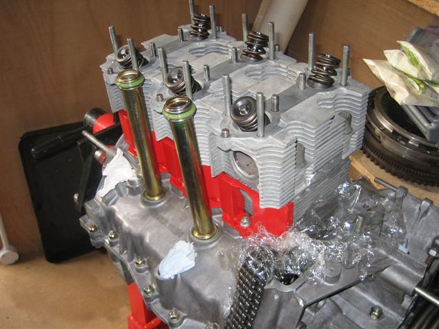
The Graphite Wrightwood racing head rings in position.
Heads on. The cylinder head studs are put on very loosely in order to locate heads, but not clamp them down. The new return tubes are also in position.
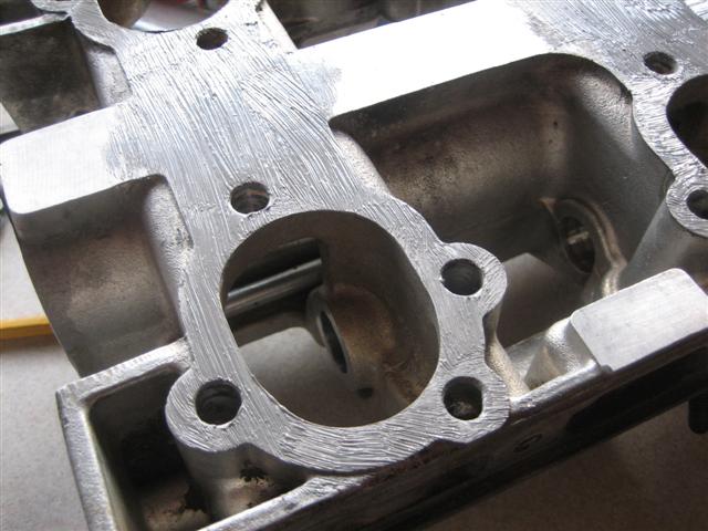
The base of the cam carrier was cleaned thoroughly. Any old 574 was gently scrapped off with razor blades, then rubbed clean with Wurth cleaning pads. I then fully degrease the surface and the top of each head with Isopropyl alcohol. Make sure that the old 574 is removed from the dowel pin sockets and also the head mounting stud (M8) holes. You don�t want this dislodging, or stopping the cam carrier seating correctly.
I applied a thin even layer of Threebond 1215 then carefully lowered the cam carrier into position.
Not seen in this photo is the knock sensor bridge which is loosely bolted to the cylinders to ensure correct location.
You then torque the cam carrier to the heads. Torque the head studs in accordance with the Porsche manual, then torque up the knock sensor bridge.
A very slight bit of squeeze out between the heads and cam carrier, ideal.
At this stage it is important to test the camshaft to make sure it does not bind. With my first heads, when I got this far I could not even insert the cam shaft, let alone turn the thing. The cam carrier can distort slightly as you torque down the head studs.
The Graphite Wrightwood racing head rings in position.
Heads on. The cylinder head studs are put on very loosely in order to locate heads, but not clamp them down. The new return tubes are also in position.
The base of the cam carrier was cleaned thoroughly. Any old 574 was gently scrapped off with razor blades, then rubbed clean with Wurth cleaning pads. I then fully degrease the surface and the top of each head with Isopropyl alcohol. Make sure that the old 574 is removed from the dowel pin sockets and also the head mounting stud (M8) holes. You don�t want this dislodging, or stopping the cam carrier seating correctly.
I applied a thin even layer of Threebond 1215 then carefully lowered the cam carrier into position.
Not seen in this photo is the knock sensor bridge which is loosely bolted to the cylinders to ensure correct location.
You then torque the cam carrier to the heads. Torque the head studs in accordance with the Porsche manual, then torque up the knock sensor bridge.
A very slight bit of squeeze out between the heads and cam carrier, ideal.
At this stage it is important to test the camshaft to make sure it does not bind. With my first heads, when I got this far I could not even insert the cam shaft, let alone turn the thing. The cam carrier can distort slightly as you torque down the head studs.
03-13-2009, 08:40 PM
#29
Racer
Join Date: Dec 2006
Location: Bedfordshire UK
Posts: 310
Likes: 0
Received 0 Likes
on
0 Posts
You're doing brilliantly, what a fantastic and informative thread.
If you need a hand popping the lump back in, which looking at this you probably don't let me know as I'm only 20 mins away.......
If you need a hand popping the lump back in, which looking at this you probably don't
let me know as I'm only 20 mins away.......
03-13-2009, 11:09 PM
#30
Rennlist Member

the reason Porsche does not want you to push the o-ring all the way home on the thru bolts is because they want the o-ring to go into the recessed area of the case and then as you push the tru bolt in it seats all the up the stud. If you push the o-ring all the up the stud and then install in the case you could cut the o-ring. hope this makes sense