
My Engine Rebuild

 03-17-2009, 07:00 PM
#47
Rennlist Member
Thread Starter
Join Date: Sep 2006
Location: Welwyn Garden City, Herts England
Posts: 121
Likes: 0
Received 0 Likes
on
0 Posts
I wanted to clean up the timing chain case surfaces so I could get a good seal between the crankcase, cover and tensioners. I taped a bit of 600 grit wet and dry paper to some glass and rubbed the surfaces in order to clean off any old gasket residue and pitting as best as possible. I lubricated the wet and dry with some GT85 and changed the paper regularly. I did not want to go made so some slight pitting remained as I was worried about taking too much material off. The magnesium is very soft so it does not take long to get a decent finish. I checked each surface with a straight edge before assembly.
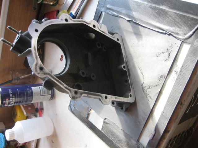
I did the same thing to the alloy thrust plates the holds the cam shaft into position.
I am not sure if I have done the right thing here or not. The Porsche manual and Waynes book says to assemble the chain case to the crankcase using the gasket dry. I decided to spread a very thing layer of the threebond 1215 onto the gasket to improve sealing. I have since come across a post by someone who has used 574 and someone else who has used Curil T, both with no ill effects to date.
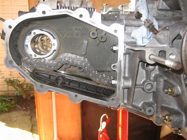
New washers and all metal lock nuts used. Not sure if I mentioned before, but I have used new all in one timing chains and new ramps both sides. You need to remove the camsahft at this take to get the chain case in cleanly.
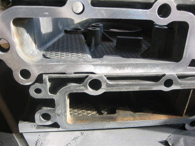
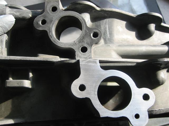
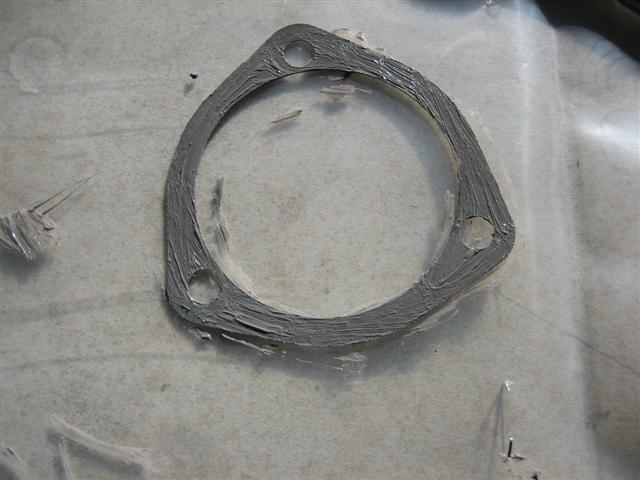
I coated the paper gasket between the cam carrier and the thrust plate in threebond 1215 both sides.
In actual fact I later found that the gasket is slightly bigger than the hole in the chain case. Therefore you have to position it onto the cam carrier, it sticks there with the 1215, then offer up the thrust plate. So not as the following sequence of photos shows.
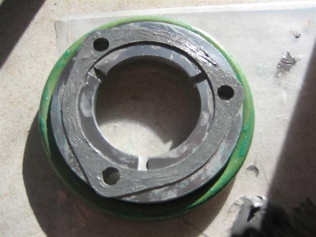
I covered the "O" ring in Curil T and the surface of the thrust plate and chain case.
Inserted the camshaft, then bolted it into position.
I did the same thing to the alloy thrust plates the holds the cam shaft into position.
I am not sure if I have done the right thing here or not. The Porsche manual and Waynes book says to assemble the chain case to the crankcase using the gasket dry. I decided to spread a very thing layer of the threebond 1215 onto the gasket to improve sealing. I have since come across a post by someone who has used 574 and someone else who has used Curil T, both with no ill effects to date.
New washers and all metal lock nuts used. Not sure if I mentioned before, but I have used new all in one timing chains and new ramps both sides. You need to remove the camsahft at this take to get the chain case in cleanly.
I coated the paper gasket between the cam carrier and the thrust plate in threebond 1215 both sides.
In actual fact I later found that the gasket is slightly bigger than the hole in the chain case. Therefore you have to position it onto the cam carrier, it sticks there with the 1215, then offer up the thrust plate. So not as the following sequence of photos shows.
I covered the "O" ring in Curil T and the surface of the thrust plate and chain case.
Inserted the camshaft, then bolted it into position.
 03-24-2009, 06:24 PM
#49
Rennlist Member
Thread Starter
Join Date: Sep 2006
Location: Welwyn Garden City, Herts England
Posts: 121
Likes: 0
Received 0 Likes
on
0 Posts
Low 964 � I have escaped for a few hours, so time for some more posts!
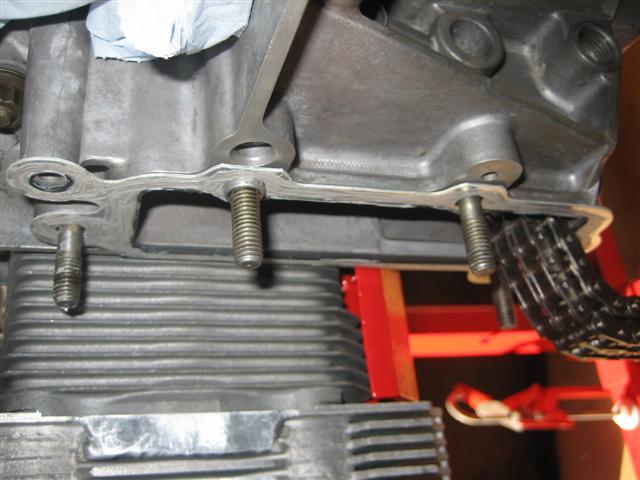
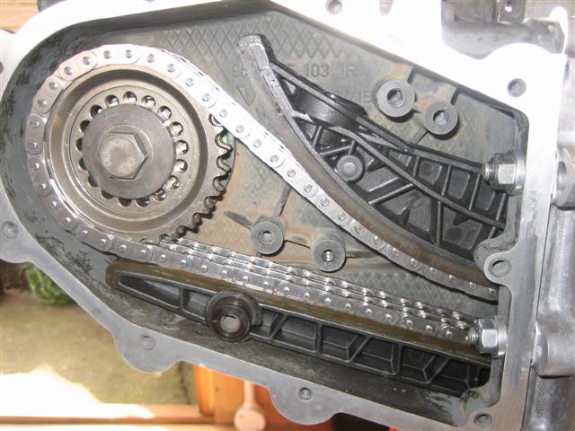
I repeated the installation of the cam, thrust plate and gasket etc to cylinder bank 4 to 6. Then installed the new timing chain ramps, which I had brought last year from Pelican in the states. When compared with the old there was not much physical wear, but I took it that these are a standard item to replace. The locating bolts in the case received new alloy washers and the pegs that locate into the timing chain housing need carefully transferring over from the old ramps. I did break a couple of the plastic �top hats�, as seen on the lower chain ramp. These are only 50p or thereabouts from Porsche, so replaced these all as well.
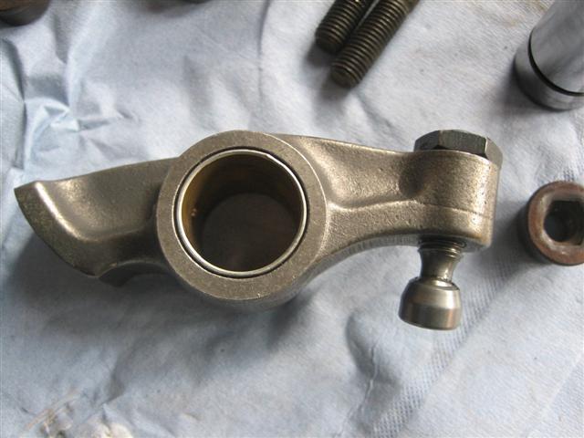
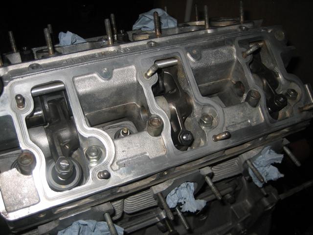
Before I could start on the cam timing you have to install the intake rockers of cylinders one and four.
The rockers and shafts were all in excellent condition, with no damage that I had noted. Whether these have been re-bushed and replacement shafts fitted previously I don�t know, but they needed nothing other than a clean.
I noticed this on the base of each valve adjustment screw.
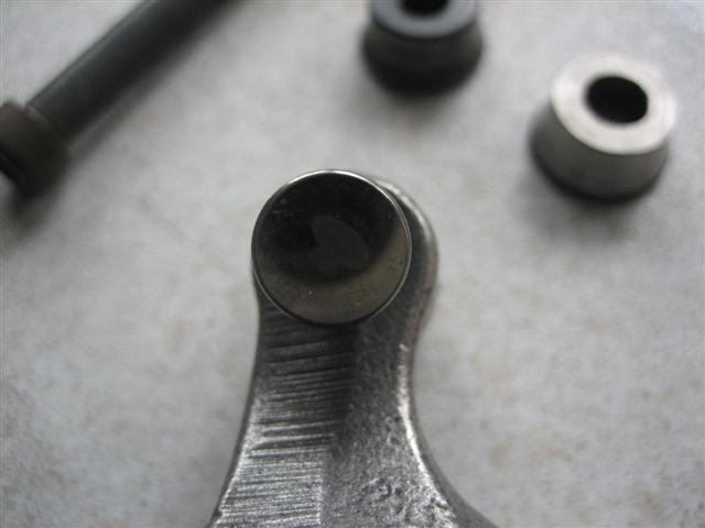
I was told this is a sign of over revving. I am not sure if it means prolonged over revving, or a single instance. I imagine it is caused by valve bounce, but I am sure someone will be able to advise the exact cause. At this point I checked for play in the base of each valve adjuster and found they varied from 0.1 to 0.25mm. The ones with the larger variance had a pronounced click when checked.
I decided to replace with new and solve both problems at once. I checked the new valve adjusting screws and they too had the similar variations on play! I can find no reference to how much play is permissible, other than checking that the foot does not come off the ball joint.
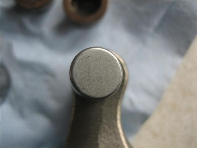
This is a new adjuster for reference.
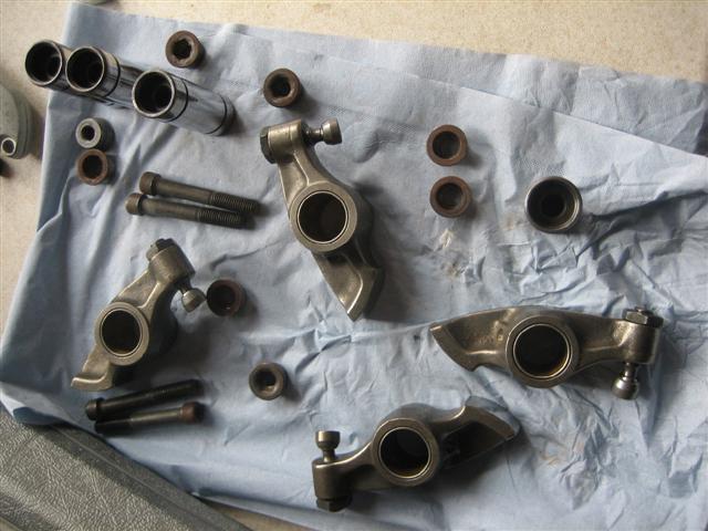
Rockers cleaned with new adjusters awaiting final cleaning before fitting.
At first I fitted the intake and exhaust rocker for cylinders one and four to save time later on. But then read that placing too much resistance on the cam whilst setting the timing, can lead to problems of the cam moving slightly when the locating dowel is removed during adjustment. I therefore took the exhaust rockers back out again and left only the intake for one and four in place.
I repeated the installation of the cam, thrust plate and gasket etc to cylinder bank 4 to 6. Then installed the new timing chain ramps, which I had brought last year from Pelican in the states. When compared with the old there was not much physical wear, but I took it that these are a standard item to replace. The locating bolts in the case received new alloy washers and the pegs that locate into the timing chain housing need carefully transferring over from the old ramps. I did break a couple of the plastic �top hats�, as seen on the lower chain ramp. These are only 50p or thereabouts from Porsche, so replaced these all as well.
Before I could start on the cam timing you have to install the intake rockers of cylinders one and four.
The rockers and shafts were all in excellent condition, with no damage that I had noted. Whether these have been re-bushed and replacement shafts fitted previously I don�t know, but they needed nothing other than a clean.
I noticed this on the base of each valve adjustment screw.
I was told this is a sign of over revving. I am not sure if it means prolonged over revving, or a single instance. I imagine it is caused by valve bounce, but I am sure someone will be able to advise the exact cause. At this point I checked for play in the base of each valve adjuster and found they varied from 0.1 to 0.25mm. The ones with the larger variance had a pronounced click when checked.
I decided to replace with new and solve both problems at once. I checked the new valve adjusting screws and they too had the similar variations on play! I can find no reference to how much play is permissible, other than checking that the foot does not come off the ball joint.
This is a new adjuster for reference.
Rockers cleaned with new adjusters awaiting final cleaning before fitting.
At first I fitted the intake and exhaust rocker for cylinders one and four to save time later on. But then read that placing too much resistance on the cam whilst setting the timing, can lead to problems of the cam moving slightly when the locating dowel is removed during adjustment. I therefore took the exhaust rockers back out again and left only the intake for one and four in place.
03-24-2009, 07:08 PM
#50
Rennlist Member
Thread Starter
Join Date: Sep 2006
Location: Welwyn Garden City, Herts England
Posts: 121
Likes: 0
Received 0 Likes
on
0 Posts
Other than the initial start up, setting the timing was worrying me the most about the rebuild. I read loads of different posts, books etc on this before I started and had tinkered around with it all during tear down and when I had been checking the valve to piston checks with the defective heads.
People appear to have used various different methods to tension the chains at this point. I had taken measurements of how much tension had been placed on both chains at tear down, but was still wary of the consequences if this was wrong. My mind was settled when I managed to borrow a pair of the Porsche specific tools to tension the chains probably from a local independent.
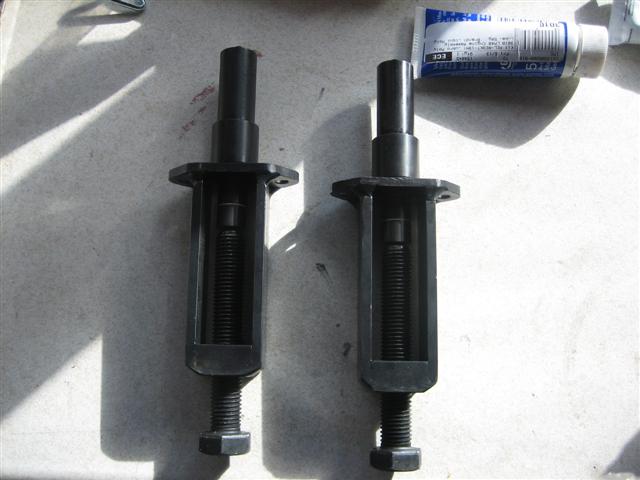
These are installed in both hydraulic tensioner holes and adjusted so that the white ring is partially obscured. The threaded bolt acts onto a plunger that then compresses a spring inside the body of the tool. I did disassemble the tools and took careful measurements of the components and spring dimension that I will post at some stage soon.
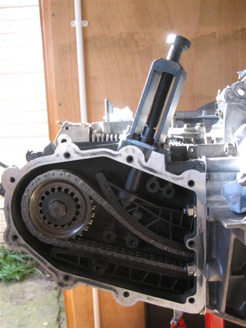
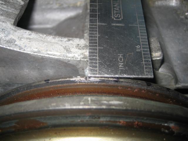
The first stage is bring the engine to TDC so that the z1 mark on the front pulley is lined up with the case parting line. As the pulley sits about 15mm away from the case I transferred the parting line with a steel rule to get this dead accurate.
Both camshafts are then rotated so that the woodruff key slot, or centre point mark are pointing upwards. This photo taken before the thrust plate was installed shows the mark and keyway.
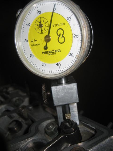
The valve adjustment can then be set (accurately) for both one and four. Having never done a valve adjustment before on a Porsche engine I did not really know what a �light drag� between the screw and valve should feel like so I decided to make the valve adjusting screw driver mentioned elsewhere on this forum compare with the traditional feeler gauge.
What I thought was a �light drag� appeared to be 0.11mm when measured with a dial gauge and the valve adjusting screw driver, if used accurately gave 0.09 to 0.1mm. In the end I adjusted the valves using the dial gauge so at least I knew one and four would be bang one for setting the timing.
I am not going to fully document the remainder of the method as it can be found in the Porsche manual plus lots of other places, but the brief idea is as follows.
Mount your dial gauge on the valve spring collar of intake one, preload with at least 10mm and zero the outer bezel
Rotate engine CLOCKWISE and key an eye on the gauge as it moves STOP when it reaches 1.26mm. Where is the z1 mark in relation to the case parting line? If you have the valve adjustment right and cam shaft key way pointing straight up to start with, then the z1 mark should be just approaching the case joint. Remove the location dowel from the cam sprocket, make sure the camshaft does not move at all and continue rotating until thez1 is bang on the case line.
Insert pin into cam sprocket and tighten cam nut. Rotate engine 720deg and check, is the z1 and parting line inline at 1.26mm? If yes, well done, if like me after several attempts it not, go inside, have tea, swear a bit at whoever is passing, then go back and try again till it is right.
When its OK your four to six camshaft should have its keyway or dot pointing down. Transfer dial gauge onto number four intake and repeat above process.
Tighten cam nuts fully and check. I found things did move a bit then so repeated the entire process and tightened the cam nuts to full torque during the adjustment to make sure nothing then moved later on. You must use the special Porsche tool to counter hold the cam sprockets or with damage something.
I then put the dial; gauge back onto intake one, checked. Then checked intake four, then intake one, then four, then one, then four, then one, then four, then one, then four until I was happy, or madder then before!!!!
Timing done!!
I then went inside and read a post that the z1 mark on the pulley can be out and not the exact TDC! Great, I now need to check this and repeat the whole process again if mine is out.
I will explain this next time.
People appear to have used various different methods to tension the chains at this point. I had taken measurements of how much tension had been placed on both chains at tear down, but was still wary of the consequences if this was wrong. My mind was settled when I managed to borrow a pair of the Porsche specific tools to tension the chains probably from a local independent.
These are installed in both hydraulic tensioner holes and adjusted so that the white ring is partially obscured. The threaded bolt acts onto a plunger that then compresses a spring inside the body of the tool. I did disassemble the tools and took careful measurements of the components and spring dimension that I will post at some stage soon.
The first stage is bring the engine to TDC so that the z1 mark on the front pulley is lined up with the case parting line. As the pulley sits about 15mm away from the case I transferred the parting line with a steel rule to get this dead accurate.
Both camshafts are then rotated so that the woodruff key slot, or centre point mark are pointing upwards. This photo taken before the thrust plate was installed shows the mark and keyway.
The valve adjustment can then be set (accurately) for both one and four. Having never done a valve adjustment before on a Porsche engine I did not really know what a �light drag� between the screw and valve should feel like so I decided to make the valve adjusting screw driver mentioned elsewhere on this forum compare with the traditional feeler gauge.
What I thought was a �light drag� appeared to be 0.11mm when measured with a dial gauge and the valve adjusting screw driver, if used accurately gave 0.09 to 0.1mm. In the end I adjusted the valves using the dial gauge so at least I knew one and four would be bang one for setting the timing.
I am not going to fully document the remainder of the method as it can be found in the Porsche manual plus lots of other places, but the brief idea is as follows.
Mount your dial gauge on the valve spring collar of intake one, preload with at least 10mm and zero the outer bezel
Rotate engine CLOCKWISE and key an eye on the gauge as it moves STOP when it reaches 1.26mm. Where is the z1 mark in relation to the case parting line? If you have the valve adjustment right and cam shaft key way pointing straight up to start with, then the z1 mark should be just approaching the case joint. Remove the location dowel from the cam sprocket, make sure the camshaft does not move at all and continue rotating until thez1 is bang on the case line.
Insert pin into cam sprocket and tighten cam nut. Rotate engine 720deg and check, is the z1 and parting line inline at 1.26mm? If yes, well done, if like me after several attempts it not, go inside, have tea, swear a bit at whoever is passing, then go back and try again till it is right.
When its OK your four to six camshaft should have its keyway or dot pointing down. Transfer dial gauge onto number four intake and repeat above process.
Tighten cam nuts fully and check. I found things did move a bit then so repeated the entire process and tightened the cam nuts to full torque during the adjustment to make sure nothing then moved later on. You must use the special Porsche tool to counter hold the cam sprockets or with damage something.
I then put the dial; gauge back onto intake one, checked. Then checked intake four, then intake one, then four, then one, then four, then one, then four, then one, then four until I was happy, or madder then before!!!!
Timing done!!
I then went inside and read a post that the z1 mark on the pulley can be out and not the exact TDC! Great, I now need to check this and repeat the whole process again if mine is out.
I will explain this next time.
03-31-2009, 05:00 PM
#52
Rennlist Member
Thread Starter
Join Date: Sep 2006
Location: Welwyn Garden City, Herts England
Posts: 121
Likes: 0
Received 0 Likes
on
0 Posts
I thought Porsche tolerances should be spot on, so initially double checked and fitted the fan housing, which believe it or not did not line up with the case parting line.
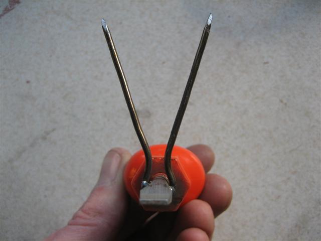
I had never bothered to check TDC with the heads off, so had to measure it now with the heads on. After half an hour searching on google, it appeared using a Piston Stop would be the easiest way to measure. You thread the stop into the spark plug hole of cylinder one and rotate the engine CLOCKWISE till the piston hits the stop. I marked the case line on the crank pulley. You then rotate COUNTER CLOCKWISE until the piston hits the stop again and mark the crank pulley. Bisect these two marks and that is TDC. I did not have a Piston Stop so messed about with an old spark plug for a while before giving up and cannibalising an old compression tester and threading a bit of studding into the end of it.
I repeated the exercise three times with varying lengths of stud projecting and each time recorded the same �True� TDC on the pulley.
The red mark below.
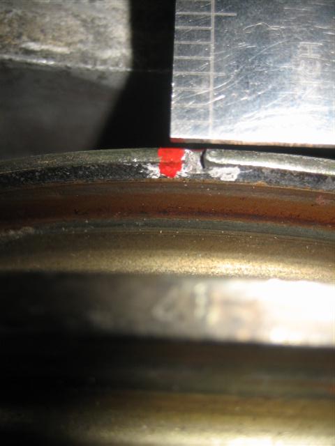
It showed �True� TDC to be approximately 1.2deg after the z1 mark. I then offered up the fan housing and the z1 mark lined up perfectly with the grove in this. Very strange.
I slackened off everything and repeated the timing adjustment with the fan housing in place using this as the TDC mark and not the case line. The time adjustment went smoothly and I am very happy with it.
Next job is to install the hydraulic tensioners and the chain case covers.
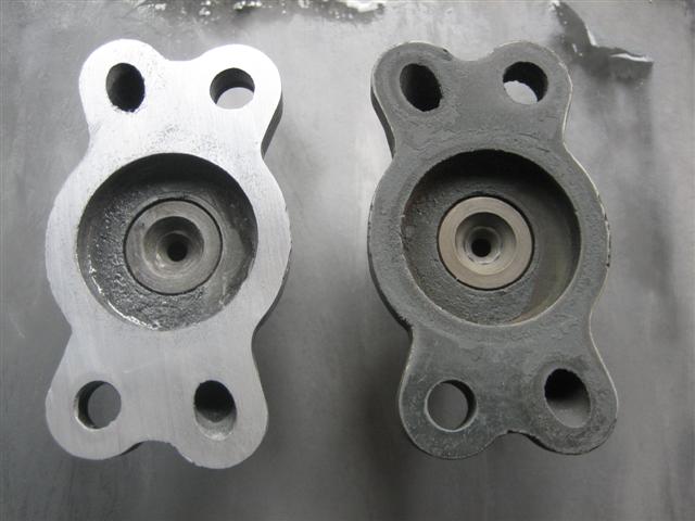
I treated the tensioner top caps in the same manner as the timing chain cases and sanded them smooth on a glass sheet with wet and dry tapped to it.
Before and After.
New gaskets again from the Wrightwood Racing set and I applied a little Curil T onto both joints.
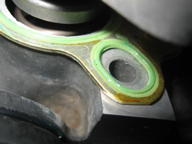
New alloy washers from Porsche (not in the Wrightwood set) and Philidas lock nuts from a local fastening supplier, cheaper than Porsche.
I applied a bead of Curil T to the chain case covers
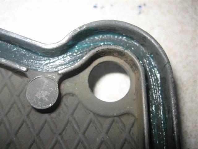
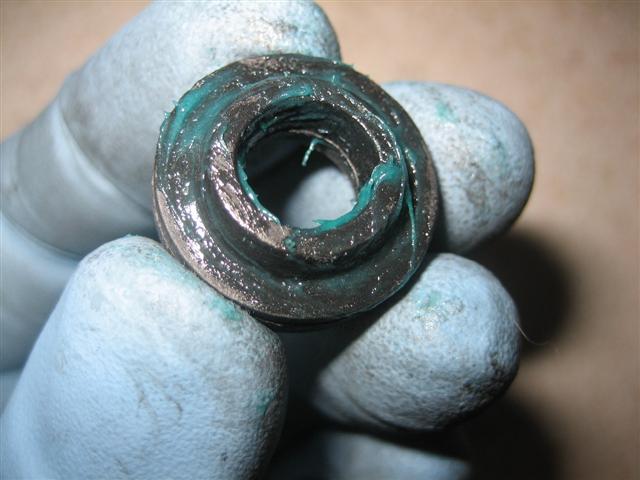
Then the gaskets
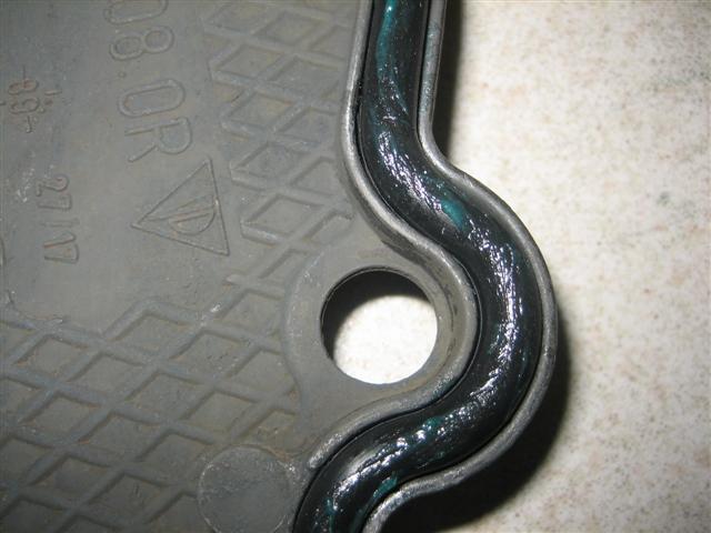
Then the new rubber grommets
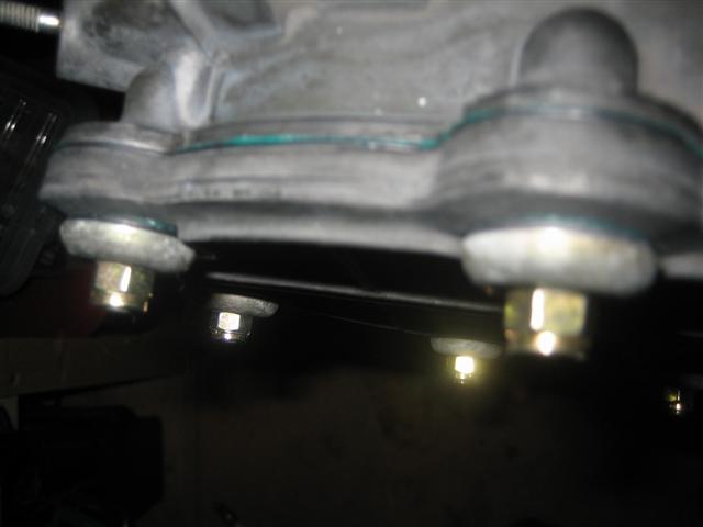
And finally fitted them all together. My original lock nuts were on the chain case studs so tight, most of the studs got damaged whilst I removed them. I replaced all studs with new and lined the Porsche coffers further,18no at �2.45 + VAT each! I used the same domed cap washers but used new Philidas lock nuts.
I had never bothered to check TDC with the heads off, so had to measure it now with the heads on. After half an hour searching on google, it appeared using a Piston Stop would be the easiest way to measure. You thread the stop into the spark plug hole of cylinder one and rotate the engine CLOCKWISE till the piston hits the stop. I marked the case line on the crank pulley. You then rotate COUNTER CLOCKWISE until the piston hits the stop again and mark the crank pulley. Bisect these two marks and that is TDC. I did not have a Piston Stop so messed about with an old spark plug for a while before giving up and cannibalising an old compression tester and threading a bit of studding into the end of it.
I repeated the exercise three times with varying lengths of stud projecting and each time recorded the same �True� TDC on the pulley.
The red mark below.
It showed �True� TDC to be approximately 1.2deg after the z1 mark. I then offered up the fan housing and the z1 mark lined up perfectly with the grove in this. Very strange.
I slackened off everything and repeated the timing adjustment with the fan housing in place using this as the TDC mark and not the case line. The time adjustment went smoothly and I am very happy with it.
Next job is to install the hydraulic tensioners and the chain case covers.
I treated the tensioner top caps in the same manner as the timing chain cases and sanded them smooth on a glass sheet with wet and dry tapped to it.
Before and After.
New gaskets again from the Wrightwood Racing set and I applied a little Curil T onto both joints.
New alloy washers from Porsche (not in the Wrightwood set) and Philidas lock nuts from a local fastening supplier, cheaper than Porsche.
I applied a bead of Curil T to the chain case covers
Then the gaskets
Then the new rubber grommets
And finally fitted them all together. My original lock nuts were on the chain case studs so tight, most of the studs got damaged whilst I removed them. I replaced all studs with new and lined the Porsche coffers further,18no at �2.45 + VAT each! I used the same domed cap washers but used new Philidas lock nuts.
03-31-2009, 05:21 PM
#53
Rennlist Member
Thread Starter
Join Date: Sep 2006
Location: Welwyn Garden City, Herts England
Posts: 121
Likes: 0
Received 0 Likes
on
0 Posts
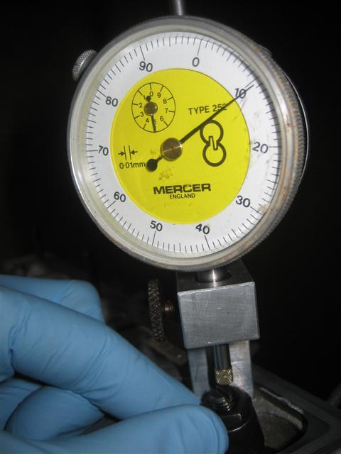
I then did my valve adjustment using the fan housing as the TDC mark. I did the first few valves with the angled feeler gauge and kept checking with the dial gauge, but after a while I was getting the feel for the feeler gauge, so just relied on this alone. I turned the engine over four times checking the clearances each time until I was happy with them all.
Initially I was going to put Curil T on the cam covers and gaskets to prevent these leaking, but decided against it as in a thousand or so miles I will definitely have the pull the covers to adjust the valves again and maybe retorque the head studs. The Curil T does not set fully, but from when I took the heads off to replace the head seals earlier in the rebuild, I know how messy it becomes. It cleans off well with Mentholated Spirits though.
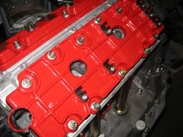
Original cam covers, cleaned up and powder coated to match cooling ducts and fan, new gaskets from the Wrightwood set.
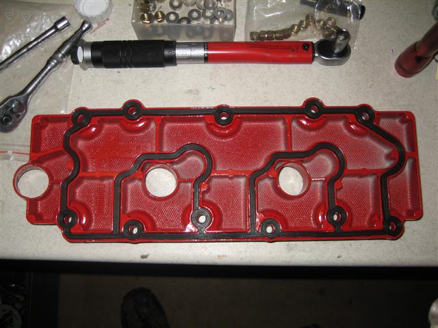
Installed and looking smart. New alloy washers from the Wrightwood set, the nuts are again the Philidas type as the Wrightwood were standard nylocs. I am not sure if this is good or bad, but all the original Porsche nuts are all metal lock nuts, so I have stuck to this. I got new plastic plug lead clips and screws also from Porsche.
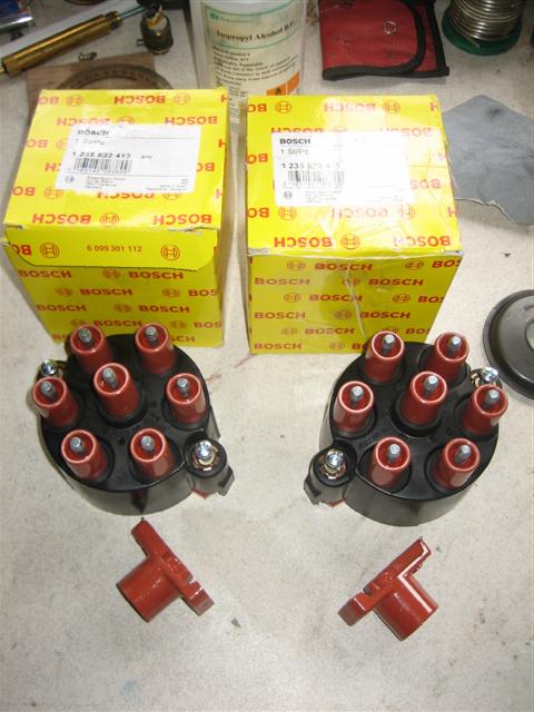
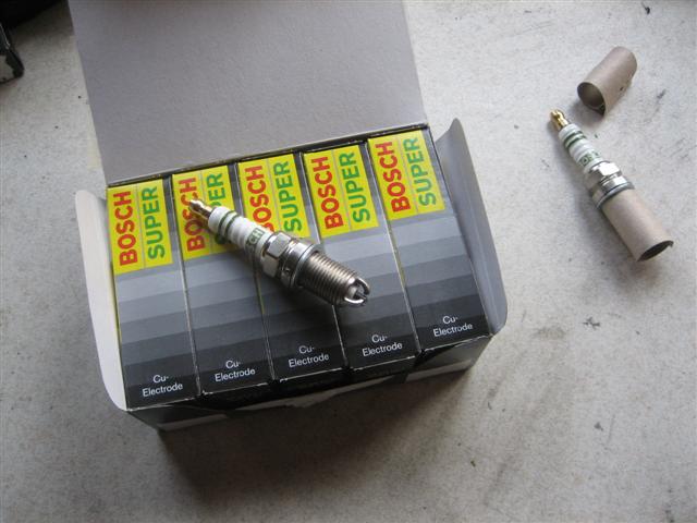
New caps, rotor arms for the distributor and plugs
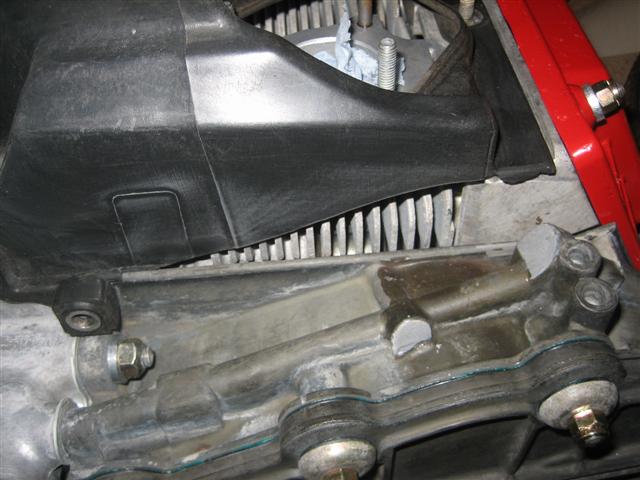
During the tear down I had noticed that the engine fan shroud was damaged around head four.
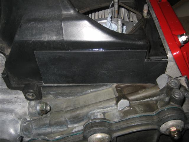
I had been looking on Ebay for a while for a replacement, but none had appeared. So I repaired the on I had with some black plastic glued to the original.
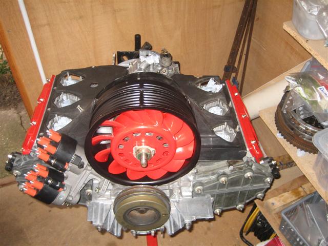
Well there she is looking very clean and smart if I do say so myself. I now need to transport it back into the garage where I can install the exhaust and injection system, power steering, heat shields etc.
Initially I was going to put Curil T on the cam covers and gaskets to prevent these leaking, but decided against it as in a thousand or so miles I will definitely have the pull the covers to adjust the valves again and maybe retorque the head studs. The Curil T does not set fully, but from when I took the heads off to replace the head seals earlier in the rebuild, I know how messy it becomes. It cleans off well with Mentholated Spirits though.
Original cam covers, cleaned up and powder coated to match cooling ducts and fan, new gaskets from the Wrightwood set.
Installed and looking smart. New alloy washers from the Wrightwood set, the nuts are again the Philidas type as the Wrightwood were standard nylocs. I am not sure if this is good or bad, but all the original Porsche nuts are all metal lock nuts, so I have stuck to this. I got new plastic plug lead clips and screws also from Porsche.
New caps, rotor arms for the distributor and plugs
During the tear down I had noticed that the engine fan shroud was damaged around head four.
I had been looking on Ebay for a while for a replacement, but none had appeared. So I repaired the on I had with some black plastic glued to the original.
Well there she is looking very clean and smart if I do say so myself. I now need to transport it back into the garage where I can install the exhaust and injection system, power steering, heat shields etc.
 03-31-2009, 05:44 PM
#56
Rennlist Member
Thread Starter
Join Date: Sep 2006
Location: Welwyn Garden City, Herts England
Posts: 121
Likes: 0
Received 0 Likes
on
0 Posts
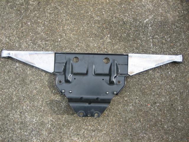
My engine tineware was not in great shape when I removed it, but other than rusting there was only one major hole.
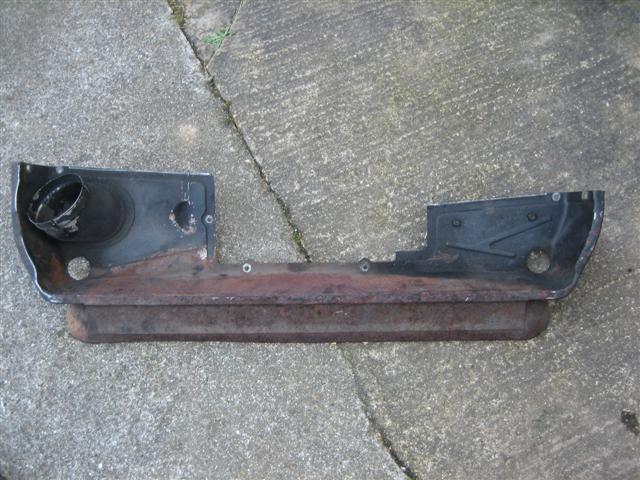
I had this sand blasted almost straight away by a guy I know through work. I was going to get it powder coated, but was not convinced that the rusting would not continue unchecked below and then appear quite soon. In the end I decided to apply two coats of hammertite black paint, wait for this to fully harden before rubbing down the bush marks and spaying with two costs of black hammerite to finish.
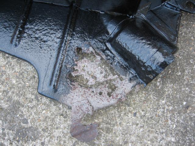
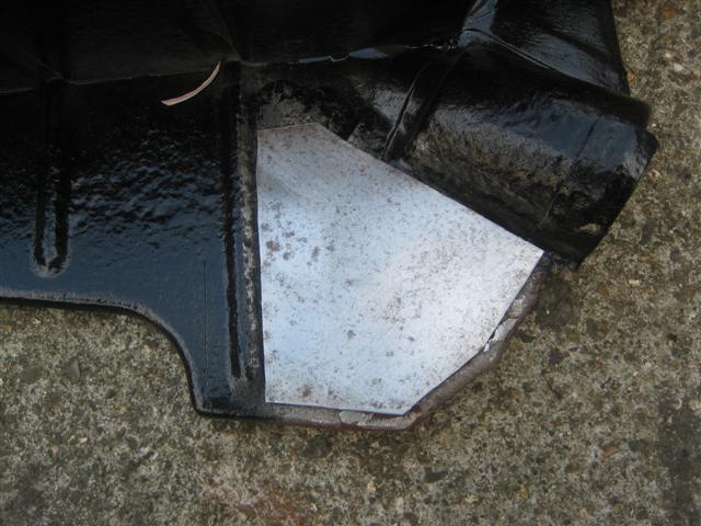
I cut a small patch and welded up the perforated area after cutting out as much rotten metal as I could below.
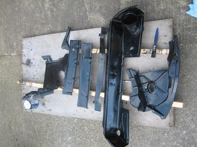
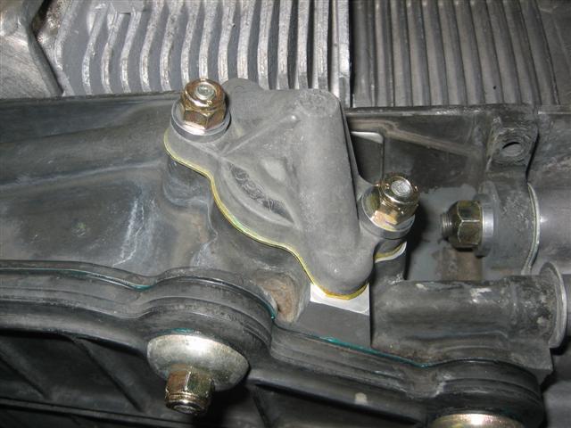
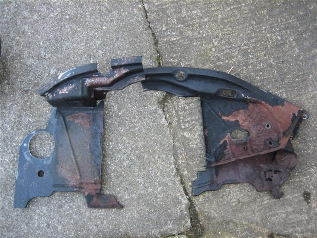
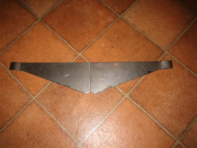
Though I had no intention of replacing the engine mounts for uprated versions at this stage, I did decide to make up some stiffening plates for the engine carrier. I looked at purpose made stiffening plates from the US, but decided just to cut some triangular sections to strengthen the locating points only.
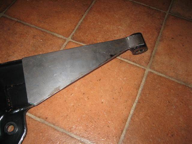
I am not a confident welder, so the same guy who did my sand blasting welded on the stiffeners for me. I then painted it all as the tinware.
I had this sand blasted almost straight away by a guy I know through work. I was going to get it powder coated, but was not convinced that the rusting would not continue unchecked below and then appear quite soon. In the end I decided to apply two coats of hammertite black paint, wait for this to fully harden before rubbing down the bush marks and spaying with two costs of black hammerite to finish.
I cut a small patch and welded up the perforated area after cutting out as much rotten metal as I could below.
Though I had no intention of replacing the engine mounts for uprated versions at this stage, I did decide to make up some stiffening plates for the engine carrier. I looked at purpose made stiffening plates from the US, but decided just to cut some triangular sections to strengthen the locating points only.
I am not a confident welder, so the same guy who did my sand blasting welded on the stiffeners for me. I then painted it all as the tinware.
03-31-2009, 05:49 PM
#57
Rennlist Member
Thread Starter
Join Date: Sep 2006
Location: Welwyn Garden City, Herts England
Posts: 121
Likes: 0
Received 0 Likes
on
0 Posts
Kevin
Great work, one question though, can I see powder coating on the insides of the rocker covers? if so is this wise?
My original covers were coated on the inside and there was no sign of this flaking or coming off after 80K. So I am assuming this is OK. The insides have only been lightly over sprayed.
Something else to worry about now!
03-31-2009, 06:09 PM
#58
Rennlist Member
Very impressive and a terrific read so far. Looking forward to more updates and seeing the final results. 
