
Diag interface & Software
 07-16-2006, 10:57 PM
#301
Instructor
Join Date: Dec 2005
Posts: 132
Likes: 0
Received 0 Likes
on
0 Posts
Originally Posted by Red rooster
Ray,
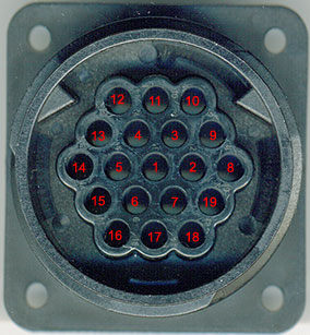
The the 964 OBD1 round connector,
Ignition switched +12 volts Pin 13
Battery +12volts Pin 12
K Pin 8
L Pin 7
Ground 0volts Pin 10
This is a great thread thanks to Dougs software. The OBD2 specification calls for a 510 ohm pull up on the K line. It may be that on some cars the 3.3 k needs to be reduced ?
As someone who is involved in " talking to DMEs " I really liked your minimalist circuit !!
I have a Hammer but think that this whole 964 diagnostics area needs opening up to all !After all its hardly current technology !!!
Good luck to all involved
Geoff
I'll update schematic and repost.
Yes I've seen interfaces say 510 ohms. I found with that value the auto's controller was not able to pull the K line to ~ 0 Volts. In fact the shop manual shows this in its debug. For my interface to receive the data the voltage level must be ~0.5V or less. i.e. I chose 3.3K. The other issue is this pullup resistor must pull the signal to ~12Volts. The higher the value the slower it rises distorting the bit width. My DME is 9600 baud. I use a 10 foot cable between OBD and interface. i.e. compounding this potential problem. But the scope shows I can use >10k and still not have distortion. I don't feel the DME cares how much current it sinks based on the values 510, 3.3k 10k. The manual also worries about noise in the data. Maybe their testor is noisy. :-) I don't see any.
With all that being said: If the circuit was being made into a pcb assy. I would use a 2n3906 and bias it to recognize as a low level 6 volts or so. This means I have to add another transistor and a different kind of transistor. i.e. less minimum. :-)
--------------------------
EDIT: OBD 2. I've seen 38,800 baud in scantool programs. I don't know what maximum baud rate OBD2 allows but this is probably the reason for 510 ohm pullup. A short cable between OBD and interface is another fix/aid.
--------------------------
I'm responding re my interface in detail. I know I'm no expert. With this detail someone can point out my error and I'll fix it. I'm not up in arms.
Question. In my 1995 I have to change jumper positions. Does 964 have only one K line? 993 has 2. DME has one pin for K and the others have a second pin.
All except airbag are woke up on L pin and Airbag is woke up on its K line.
Can 964 talk to all controllers with one setup? L pin 7 for 5 baud poll and K pin 8 for data.
Thanks for the input,
Ray
Last edited by raycm; 07-16-2006 at 11:28 PM. Reason: reson for 510 ohm
 07-17-2006, 12:54 AM
#302
"In my 1995 I have to change jumper positions. Does 964 have only one K line? 993 has 2. DME has one pin for K and the others have a second pin.
All except airbag are woke up on L pin and Airbag is woke up on its K line.
Can 964 talk to all controllers with one setup?"
The 964 was designed with a single bidirection bus (K-line) with the L-line
used as an address/command bus. Thus all ECUs use a common K-line.
With OBDII only the DME uses pin 7 on the OBDII connector, J1962.
Because of this, testers/scantools, e.g. PST2, require a multiplexer to select
the other ECU K-lines on the OBDII connector. Later cars use a CAN bus
where all ECUs use a common bus, kinda like the bus system in a PC.
The late 993 (OBDII) requires a more complex protocol (9141) to access the DME data.
As a result the 964/early 993 scantool software's protocol won't access the later cars.
But this is not a problem, as OBDII scanners can be purchased for less than $100.
Last edited by Lorenfb; 07-17-2006 at 01:28 AM.
07-17-2006, 04:32 AM
#303
Racer
Thread Starter

Note the connector picture has an error which is noted in the original post. 12v Ign should be pin 13 NOT 15 I forgot to erase the error when i scanned it.
07-17-2006, 08:01 AM
#304
Burgled
Rennlist Member
Rennlist Member
Originally Posted by Laurence Gibbs
Note the connector picture has an error which is noted in the original post. 12v Ign should be pin 13 NOT 15 I forgot to erase the error when i scanned it.
07-18-2006, 03:14 AM
#305
Technical Guru
Rennlist Member
Rennlist Member
- Airbag Gong Relay
- Unused
- Unused
- Unused
- OBC On/Off
- Unused
- L
- K
- Unused
- Ground
- Unused
- Battery +VE
- Ignition Power
- Pin 6 of the DME, Rev Counter
- Pin 22 of the DME, Check Engine Control On DME
- Unused
- Unused
- Unused
- Pin 21 of the DME, Knocking
The Bosch Hammer uses Pin 12 instead of 13.
Last edited by JasonAndreas; 07-18-2006 at 04:53 AM. Reason: poor reading comprehension on my part
07-18-2006, 04:15 AM
#306
Racer
Thread Starter
Is there software availiable that would work with the interface for the later obd11 cars(boxster specifically)? I have tried VAG-com and scantool.net's software(with an elm interface) and can talk to the dme but nothing else on my Boxster, I assume all the later cars have the dual k line? and so the opto interface won't work without a small mod to switch between the two ?
07-20-2006, 12:36 AM
#307
Instructor
Join Date: Jan 2006
Location: Edmonton Alberta
Posts: 166
Likes: 0
Received 0 Likes
on
0 Posts
For those who want to know what the kit looks like that John Speake is selling, I've attached a picture. First Canadian group buy is completed!
Last edited by f11; 04-12-2008 at 10:46 PM.
07-31-2006, 03:39 AM
#308
Instructor
Join Date: Jan 2006
Location: Edmonton Alberta
Posts: 166
Likes: 0
Received 0 Likes
on
0 Posts
Finally found the time to get this kit completely assembled (pix later) today. Spent more time building the serial cable than putting the rest of the kit together and testing it.
As Doug's software is a bit thin on documentation (not a complaint, just an observation), can anyone tell me some things about the .cfg file:
- what is the format of the Actual lines - I think I see the pattern, but wouldn't mind the formal schema if its available
- can I just read Input or Actual values from any address and figure out what they are by trial and error? Do I risk doing anything by just *reading* addresses?
- what do the variables in the file mean (the "n" for example)? What are the constants I see used in various calc's - do they just convert A/D bit count ranges to analog engineering values?
- in the ABS and AirBag sections, am I better to not go experimenting in the registers - do I risk setting off an airbag by poking around in there? Are the Test parameters a danger zone?
I see someone posted info about 993 registers in their .cfg file - but in some cases their baud rate and base address are different from the default .cfg file that came with ScanTool V4... can I copy his lines into my .cfg file and use them? If they are meaningless, will they cause me any grief?
Tonight I just tested the interface on my car with the key "ON". Sure enough, I had to cut one leg of the D4 LED. Anyway, tomorrow I'll run the interface while I drive to work to see how the real time values fill in and how fast they update. I'm used to an OBD-II ISO 9141-2 interface which updates very slowly in my Miata, and I'm hoping this is a bit quicker.
Question for Doug - any interest in adding a "record" and "playback" mode so we can sorta log our real time monitoring?
Thanks Doug, Andy, Laurence, and John for your hard work in putting the pieces of this kit together. And John, your connector kit is worth the price of entry - because its keyed to my socket, there's no way I can stick the wrong pin the wrong hole, and the plug stays put once plugged in... and the pins seat nice and secure at just the right height so they don't stick out beyond the plug lip.
Rod
08-03-2006, 08:37 PM
#309
Pro
Join Date: Jan 2005
Location: St. Albert, Alberta, Canada
Posts: 696
Likes: 0
Received 2 Likes
on
2 Posts
For those building / interested in the circuit on the 993 board, there is updated diagrams that are easier to read than the first one posted. See posts #81 and 85 and 89:
https://rennlist.com/forums/showthre...3&page=6&pp=15
I'm giveing it a try now that it's (more) legible than the original post...more to follow.
https://rennlist.com/forums/showthre...3&page=6&pp=15
I'm giveing it a try now that it's (more) legible than the original post...more to follow.
08-04-2006, 02:49 PM
#310
Pro
Join Date: Jan 2005
Location: St. Albert, Alberta, Canada
Posts: 696
Likes: 0
Received 2 Likes
on
2 Posts
Built the 993 circuit board and it works! 
The idle adaptation only took about 10 seconds.
I get '23=Oxygen regulation at stop (intake air leak?)' and
'32=Knock sensor 2' errors. (anyone tell me if that is the sensor on the air filter side or the blower motor side?).
So i know the ECU communication works!
Also get '43=Rear blower motor speed 1' from the CCU (so that one works too)
My car doesn't have an air bag so that one doesn't matter
One problem is that I can't connect to the ABS/PDAS system - and yes, mine is a C4. Could there be too much resistance on the "L" wake up line to wake up the system? or maybe early models don't talk (mine is a 08/89 build).
Frank
08-04-2006, 03:14 PM
#311
Rennlist Member
Cool Frank.
I'm lazy (actually, don't have the time with 2 little kids) so I will be purchasing the prebuilt board from Andy... IF I get lucky and snag one when he gets more in!
Awesome job Doug, Andy, Laurence and John... and thanks to those who have made it clear that this is really easy to do. Thanks all!
This removes the last reason I would ever have to take my pcar into a shop for any sort of repair. Gotta love it.
Last edited by 92964cab; 08-04-2006 at 07:26 PM.
08-04-2006, 03:55 PM
#312
Three Wheelin'

Join Date: Dec 2004
Location: Halifax, Nova Scotia , Canada
Posts: 1,779
Likes: 0
Received 0 Likes
on
0 Posts
Frank,
Some of the systems , especially the heater, are a bit slow . As a generalisation I always see what faults are logged , clear them and read again with just ignition on and then the motor running.
Anything that is still there is a hard fault !A quick drive will pick up real running faults.
Not unusual, with a hammer, to see pages of heater faults . All cr*p.
I guess what I am saying is dont start buying parts just because you have seen a fault once !!
Quite a lot of silly running problems dont flag faults and thats where actual values become really useful .
This stuff really allows you to see what the DME believes is happening !
All the best
Geoff
08-04-2006, 04:05 PM
#313
Burgled
Rennlist Member
Rennlist Member
I am trying to trouble shoot the circuit board I got from Andy a while back. It worked great for a while but now doesnt. When I run 12v thru the board I read 6.4v on the K line and 12+ on the L line. Is this correct and is there any other test I can do with a basic multimeter to see if it the board or something else. It worked great for 5 or 6 ties and then stopped connecting. The board had a burn smell when it quit but shows no sign of burned resistors.
08-04-2006, 04:20 PM
#314
Three Wheelin'
Join Date: Dec 2004
Location: Halifax, Nova Scotia , Canada
Posts: 1,779
Likes: 0
Received 0 Likes
on
0 Posts
Jim,
Sounds like the K line driver has cried enough. With just 12v applied the K line should be pulled to +12 through a 510 ohm resistor .
All the best
Geoff
Sounds like the K line driver has cried enough. With just 12v applied the K line should be pulled to +12 through a 510 ohm resistor .
All the best
Geoff