When you click on links to various merchants on this site and make a purchase, this can result in this site earning a commission. Affiliate programs and affiliations include, but are not limited to, the eBay Partner Network.
Any chance you can post pics of your wiring corrections.
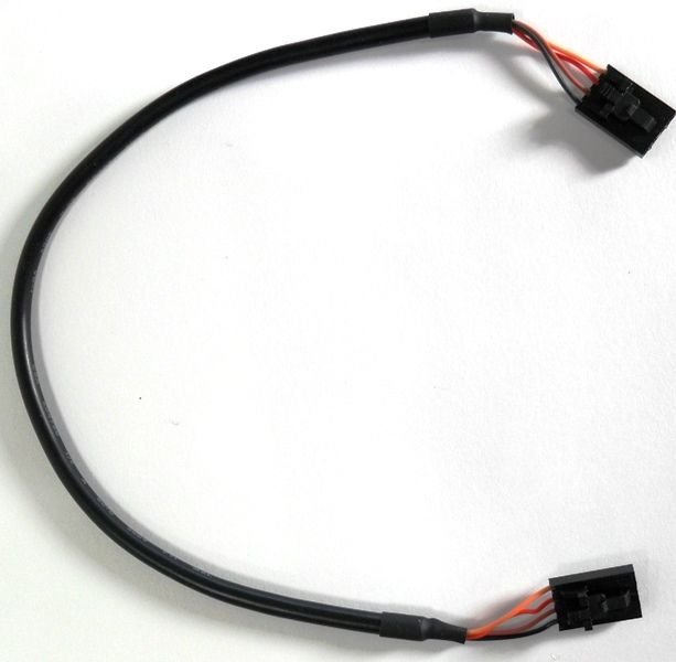
I never did receive a logger cable when I bought the Rogue setup used
I can build my own just need the configuration.
I will read through things later in case I missed any related info but too busy at work right now👍
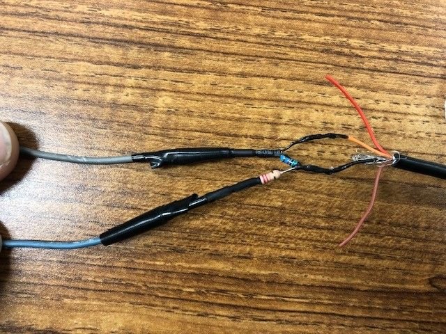
If Grey is the ground like it's supposed to be... then Grey AND Blue connect to each other through a "Y" of resistors and attach to the Black wire on the HULOG side. The Grey wire is also connected directly to the Orange wire on the HULOG side in a way that bypasses all the resistors.
To this👍 That helps. I think I can now make myself this
Originally Posted by Auto_Werks 3.6
If Grey is the ground like it's supposed to be... then Grey AND Blue connect to each other through a "Y" of resistors and attach to the Black wire on the HULOG side. The Grey wire is also connected directly to the Orange wire on the HULOG side in a way that bypasses all the resistors.
This is where i screwed up.... I wired everything in to the harness because I actually had M-tune stuff before I got this DME with the super nice external plug. For some reason I lost my mind and thought I was using WB02 external because I had added a sensor. I totally forgot it would look at the plug on the back of the M-tune DME if I did that.
As a side question, I don't actually know what the altitude correction sensor looks like.... But when I cut the wire off of Pin 30 wouldn't that fully disconnect the sensor from the system? Pin 30 on the DME pinout is "altitude correction"
When It's set System control > Disable > Alt comp, as you reference above, does that mean the ECU is using closed loop feedback from the wideband sensor to help adjust the global fueling to hit the AFR targets on the table?
Thanks for typing all of that out!
the altitude correction sensor sits to the right of the dme /klr kick board, pull back the side carpet It's round with a 2 pin connector
When alt bias is disabled it no longer uses that circuit to calculate altitude. It then just passes the input it does see to the logger. The wb02 input isn't actually used for any calculations in the dme. It's only purpose is for logging only. I would just unplug the sensor to be safe.
I believe altitude correction works like this... The dme sends a voltage to the altitude sensor , the altitude sensor can either be open or closed, if it's open, ground will return on pin 30, but if it's closed the voltage is passed back to the dme on pin 30. Depending on what signal the dme sees, it applies compensation or not. So by disabling "alt bias". You stop the dme from sending and acting when receiving that signal to the altitude sensor, therefore it's always reading ground ( no correction). This dummy circuit is then used to read the wb02 signal instead of doing nothing. Mtune repurposes the circuit in this way to not use altitude correction, but to display the wb02 signal in the logger instead.
.
Last edited by mahoney944; 01-22-2020 at 04:40 PM.
Thanks for posting this info it helps immensely I do appreciate it however one thing is puzzling me why did you install those resistors there on that hulog wire harness hookup? Shouldn�t one wire in hulog get merged into pin #16 then one get spliced into the cut pin #12 on dme side then engine side terminated/not needed?
Thanks for posting this info it helps immensely I do appreciate it however one thing is puzzling me why did you install those resistors there on that hulog wire harness hookup? Shouldn�t one wire in hulog get merged into pin #16 then one get spliced into the cut pin #12 on dme side then engine side terminated/not needed?
I did not install those resistors, They came that way from Rogue. I found them when i started doing the pinout and stripped off he heat shrink.
It seems like the lindsey racing version of the logger has a different board inside that cuts the signal voltage, and doesn't require the inline resistors.
Ok great I understand what�s going on now any chance while you have that peeled back you could
measure the resistance of both of those resistors for us if not that�s ok we can probably get the stats for them from the great web search
Have any of you guys changed to a non standard fuel injector on the M-tune? My high boost tune is flirting with 400whp and I don't have any overhead on the 80#s. A friend sent me a link for a set of 1000cc injectors that should do what I need.... Is it just as simple as changing the injector latency settings, and the global fuel, and starting it up?
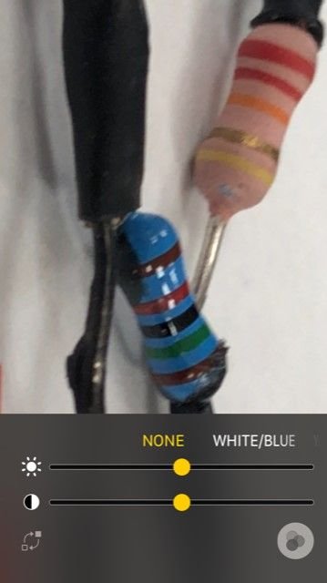
Ok great I understand what’s going on now any chance while you have that peeled back you could
measure the resistance of both of those resistors for us if not that’s ok we can probably get the stats for them from the great web search
Shawn, from the photo above, it's a 22K in series with a 15K and the way it's wired, the voltage drop across the 15K is what's being sent to the HULOG. With say 12V coming from the DME then that gets you pretty close to 5V out of the voltage divider. The HULOG is meant to connect directly to a Honda ECU and operate at +5V TTL logic levels.
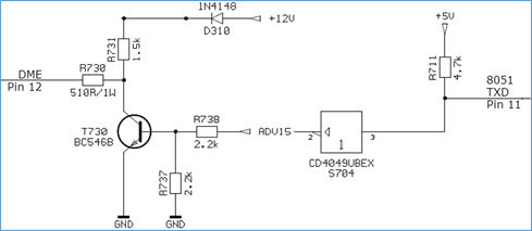
Here's what's going on inside the DME. Back when I was debugging this circuit, I pieced together parts of the analog and digital schematic to just show the serial out connection from the 8051 microcontroller. Who knows why Bosch switched the signal through that transistor pulled up to +12V but they did, so that's the reason for needing the voltage divider. The FTDI chip in the HULOG and DME Logger is a +5V part. The LR DME Logger has the same voltage drop issue to deal with, it's being done with a different circuit though.
Question I'd be interested to know ... Did the HULOG you are using come with the rest of your M-Tune equipment acquisition or did you buy it directly from Moates?
Shawn, from the photo above, it's a 22K in series with a 15K and the way it's wired, the voltage drop across the 15K is what's being sent to the HULOG. With say 12V coming from the DME then that gets you pretty close to 5V out of the voltage divider. The HULOG is meant to connect directly to a Honda ECU and operate at +5V TTL logic levels.
Here's what's going on inside the DME. Back when I was debugging this circuit, I pieced together parts of the analog and digital schematic to just show the serial out connection from the 8051 microcontroller. Who knows why Bosch switched the signal through that transistor pulled up to +12V but they did, so that's the reason for needing the voltage divider. The FTDI chip in the HULOG and DME Logger is a +5V part. The LR DME Logger has the same voltage drop issue to deal with, it's being done with a different circuit though.
Question I'd be interested to know ... Did the HULOG you are using come with the rest of your M-Tune equipment acquisition or did you buy it directly from Moates?
i bought them used, but I�m fairly confident they came from rogue, not from motes. Pretty sure the cable converter from 4 wires to 2 was something that rogue produced. I doubt it was an end user... but it could have been. Especially since one of them was wired incorrectly.
How do you change the scale of the wideband o2 sensor? LR requires ones that have a 0-5V linear output. The meter I have (in fact all autometer branded do this apparently), outputs 0-4V linear. So i'm getting erroneous AFRs on my logger.
Originally Posted by markl951
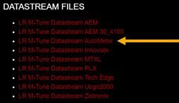
All the different .adx files you can download from LR are just so TunerPro can handle the different wideband O2 sensors voltage scaling options passed from the M-Tune DME serial port. If you don't have a wideband O2 sensor and or not running the analog voltage into the DME then any of the files should work the same for you. The .adx file definitions are locked with a password.
Can anyone make me one of these harnesses If i buy the tuner direct from Motes? I will gladly pay accordingly. I have the legacy version M-Tune (not lindsey) but am using their METAL MAF TUBE replacement made for the early plastic versions
How do you change the scale of the wideband o2 sensor? LR requires ones that have a 0-5V linear output. The meter I have (in fact all autometer branded do this apparently), outputs 0-4V linear. So i'm getting erroneous AFRs on my logger.
Are you using this datastream .adx file with TunerPro and your DME Logger? Is your logged AFR off by a lot or a little? What does "erroneous AFRs" mean?
I have the Innovate MTXL. That gauge has a separate Innovate software tool that allows you to modify the scaling of the linear output voltage. In my installation, there is a slight bias (~300mV) to the voltage output causing the AFR calculation to read a point or two high compared to the digital readout on the gauge panel. After trying different power and ground scenarios I still could not figure out where the bias was coming from so I used the Innovate software to change the output voltage curve slightly. The DME logger now reports what the gauge is showing.
Who knows. Maybe the linear output voltage was right all along and the digital readout was wrong?
I am using the AutoMeter datastream file. I am showing 16.5 AFR on the logger while the gauge shows 14.7. I was thinking that it may be a grounding issue and, upon further reading, an issue with the altitude compensator (which is probably still connected). The output of the autometer has a signal and ground. The signal only goes into the ECU so a plausible explanation is that the ground is off.
So I checked the grounds and it was only causing a 0.2 AFR error. So it isn't a grounding issue and it points to a software issue. My idle AFR sits between 14.5 and 15.0 per the autometer gauge, but TunerPro RT reads 16.5 AFR. I know there is probably a scaling issue between what voltage my gauge is sending to the DME and the conversion in the datastream file.

 01-22-2020, 12:11 PM