When you click on links to various merchants on this site and make a purchase, this can result in this site earning a commission. Affiliate programs and affiliations include, but are not limited to, the eBay Partner Network.
So I checked the grounds and it was only causing a 0.2 AFR error. So it isn't a grounding issue and it points to a software issue. My idle AFR sits between 14.5 and 15.0 per the autometer gauge, but TunerPro RT reads 16.5 AFR. I know there is probably a scaling issue between what voltage my gauge is sending to the DME and the conversion in the datastream file.
Pretty much the same thing I was seeing. Not my preference for the long term but for now I'm powering the WBO2 from the same +12V that sources the DME power, both power and ground wires so I have no ground offset voltage between the two. I still saw the same AFR difference.
I thought it would be easy to just customize the .adx file for my situation but they are password protected. That forced me to modify the MTXL's output voltage curve instead. I'd still like to figure this out someday. Just haven't had the time.
That forced me to modify the MTXL's output voltage curve instead. I'd still like to figure this out someday. Just haven't had the time.
I don't think I have the option to modify the output voltage of the autometer. I went with the analog needle gauge for a more classic look.
I figure I can wire up and program an arduino to scale the voltage to my needs, but I don't know how they scaled it exactly. I know they are looking for 0-5V in, but I don't know what that correlates to on the AFR side. Mine should be 10-18 AFR, but who knows if they scaled theirs to like 6-20 AFR or something?
You don't want to change the scaling you need to adjust the offset. If you're using the autometer datastream then the DME Logger/TunerPro is expecting the 0-4V input. This is from the Autometer datasheet. Volts = 0.5 (AFR - 10) or AFR = 2 (Volts) + 10. You want your Arduino to read in the analog voltage, calculate the AFR, offset that AFR to what you think it should really be (should be a constant offset across the range) and then recompute a new voltage based on that. Send that new voltage out to the DME logger. Sounds to me like you need to lower the voltage a bit in order to trick it into reporting the right AFR. A simple resistor divider might do just the same.
You don't want to change the scaling you need to adjust the offset. If you're using the autometer datastream then the DME Logger/TunerPro is expecting the 0-4V input. This is from the Autometer datasheet. Volts = 0.5 (AFR - 10) or AFR = 2 (Volts) + 10. You want your Arduino to read in the analog voltage, calculate the AFR, offset that AFR to what you think it should really be (should be a constant offset across the range) and then recompute a new voltage based on that. Send that new voltage out to the DME logger. Sounds to me like you need to lower the voltage a bit in order to trick it into reporting the right AFR. A simple resistor divider might do just the same.
Interesting, I thought I would have to scale it. I'll have to take some real time readings. If I can figure out a way to log the raw voltage from the gauge, I should be able to math my way through it
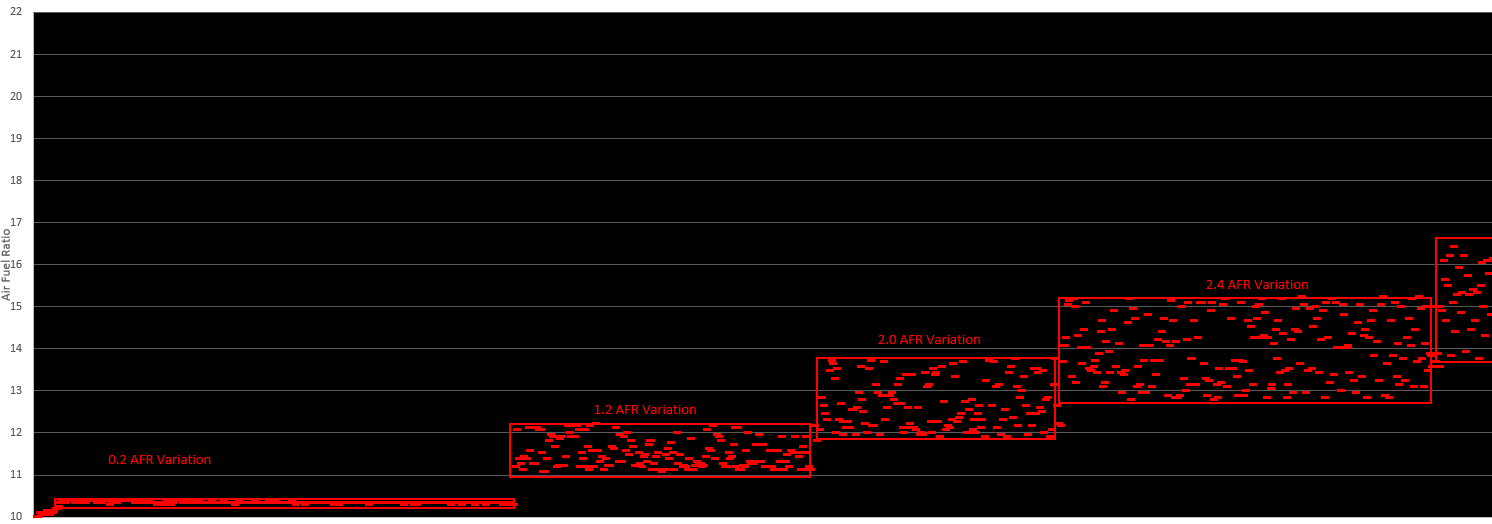
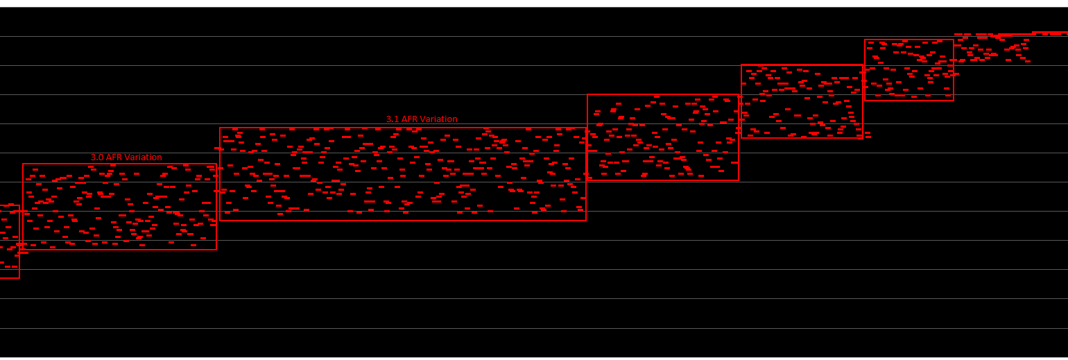
I ended up logging some data to see how an Arduino would work as a voltage converter. I'm pretty sure the PWM of the Arduino (500hz) is throwing off the AFRs and they aren't stable. Even though my multimeter shows a steady voltage, I am confident that the PWM is causing the errors. I tried a basic filter to smooth out the PWM, but it didn't work. For some reason the input pin for the WBO2 for logging shows a 5V potential (very weak - and would drop under a load). This made my filter useless.
I stepped the voltage up from 0 to 5V in 0.5V increments on the Arduino and output that into the WBO2 input on the DME. From there I would take the AFR readings from the log to make a conversion. The graph shows the resultant AFRs over time as I stepped them up. The AFRs vary widely and produce a lot of error (due to the PWM).
Next, I plan to try using an Arduino that has a true analog voltage output pin (not PWM). Hopefully, this will produce a different result.
That and a RC filter and you should be able to get nice and smooth voltage outputs. If you need more current, you can run it through an op amp voltage follower... http://www.learningaboutelectronics....ltage-follower
Never knew you could change the frequency of an arduino. Will be doing that next. Thanks for the op amp, i'm going to learn more about them. Good suggestions.
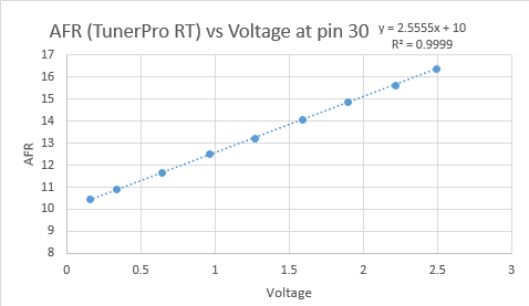
So the Nano with the DAC on it did pretty well. It doesn't have enough voltage "scale" on it, therefore i'll have to amplify it slightly anyway. But the data is so much smoother. Only like 0.1 AFR variances (perfectly acceptable). Based on the data it looks like the Autometer profile in Tuner Pro RT doesn't match the documentation.
Based on Autometer AFR = 2 x Volts + 10
It looks like TunerProRT is AFR = 2.5 x Volts + 10 (see below.... y = 2.555x + 10)
So a simple conversion factor of 0.8. This will greatly simplify the electronics. I should be able to make a simple voltage divider circuit followed by a buffer to scale the voltage down by a factor of 0.8 V. More to follow up when I get my Op Amps in this week.
It would be nice to simply change the code, but no replies from Lindsey Racing (even if they knew the password, I doubt they would give it out) and I won't even try Joshua since he is out of the game.
Last edited by PorscheFanatic202; 11-08-2020 at 08:28 PM.
Does anyone know why PIN 30 of the DME has a positive voltage coming out of it? It is the altitude compensator circuit. Pin 30 connects to the altitude switch, which is then connected to ground. It is causing errors in the signal being sent from my AFR gauge.
Does anyone know why PIN 30 of the DME has a positive voltage coming out of it? It is the altitude compensator circuit. Pin 30 connects to the altitude switch, which is then connected to ground. It is causing errors in the signal being sent from my AFR gauge.
How is pin 30 causing errors in your AFR gauge?? Pin 30 has a "pull up resistor" inside the DME that brings the voltage level up to 5v (with very little current). When you head up to high altitude, the sensor closes to ground and pulls pin 30 down to ground. It's a super common electronics thing that prevents the line from just floating around and confusing the i/c comparator. This way, the DME always sees either 5v or ground (in the absence of a country code plug anyway).
How is pin 30 causing errors in your AFR gauge?? Pin 30 has a "pull up resistor" inside the DME that brings the voltage level up to 5v (with very little current). When you head up to high altitude, the sensor closes to ground and pulls pin 30 down to ground. It's a super common electronics thing that prevents the line from just floating around and confusing the i/c comparator. This way, the DME always sees either 5v or ground (in the absence of a country code plug anyway).
It's not causing errors in my aftermarket gauge. I believe it is causing an error in the logger. This pic shows the circuitry I have set up. I'm thinking that pull up resistor is causing an error.
I was just thinking. In the instructions from Rogue, he has us cut a resistor on the board. Is that the pull-up resistor that we cut? I just sent my ECU to Focus 9 to be redone, perhaps that resistor was reinstalled (except now in a surface mount form).
Ah, does the Rogue system use pin 30 as a data logger input?
The pull up is a precision 1k ohm labelled R661 according to the old FRWilk DME schematic. You'd want to confirm that in the DME (I haven't). What issue are you experiencing? Hard to believe Josh would have used pin 30 as a logger without addressing the pull up. I don't know enough about the Rogue system to tell you if it needs that pull up for anything. If not, clipping it seems fairly harmless if you are no longer using the altitude sensor.
I was just thinking. In the instructions from Rogue, he has us cut a resistor on the board. Is that the pull-up resistor that we cut? I just sent my ECU to Focus 9 to be redone, perhaps that resistor was reinstalled (except now in a surface mount form).
I can confirm in the morning but, off the cuff, I thought the resistor that gets clipped is on pin 28, which is repurposed for the MAP sensor.
You are correct... It is for the MAP not pin 30. Are you willing to share that schematic? I have been looking for that. On a different note, I just saw that Focus 9 is now beta testing his OBD2. I may support that instead of going further down this rabbit hole.


 10-27-2020, 09:34 PM


 If you need more current, you can run it through an op amp voltage follower...