
944 Transmission Walkthrough (image heavy)
 03-20-2012, 07:25 AM
#1
Drifting
Thread Starter
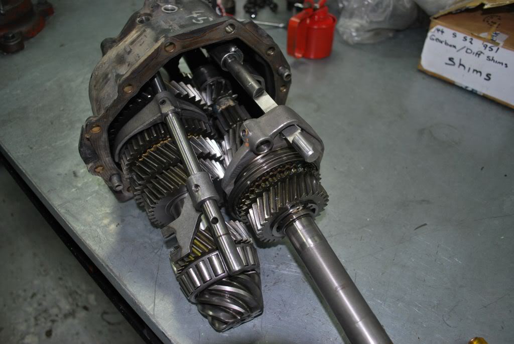
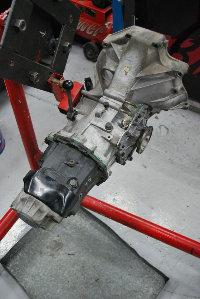
Well i have been meaning to put this together for some time. Here is a general walk through of our 944 Transmissions. This one in Particular is a 944 turbo trans, We are setting it up to receive a 944 S2 crown wheel and pinion and an aftermarket Modena LSD. Obviously without the right tools its going to make things a bit difficult, but not impossible.
So we step into the tear down
Step 1.
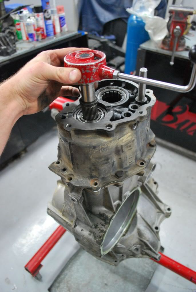
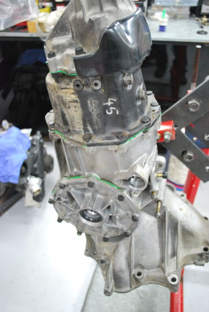
set the Gearbox up so that it can be worked on

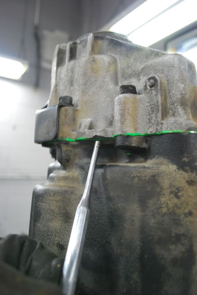
Step 2
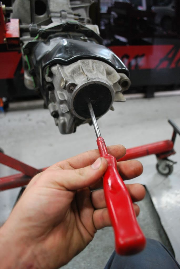
Lock the CV flange with a screw driver and remove the 6mm allen bolts

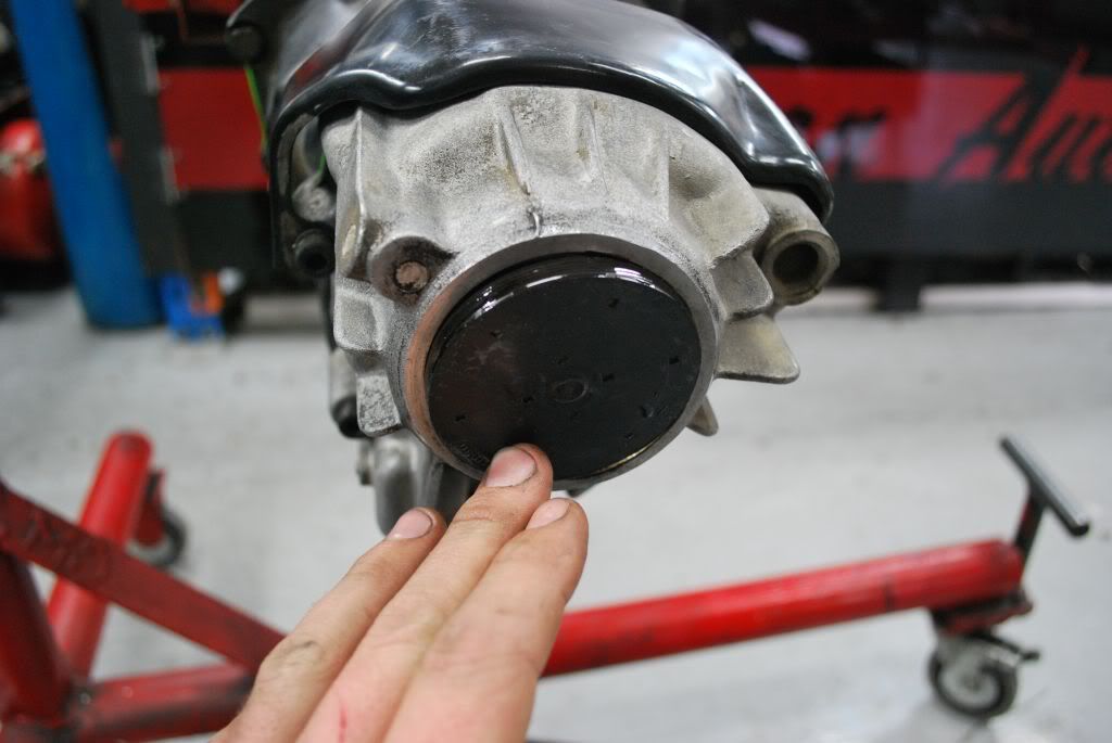
Step 3
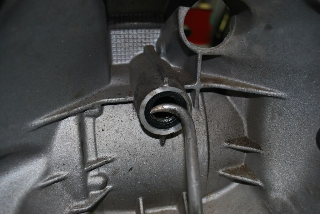
With a screw driver puncture the rear seal and pry it out
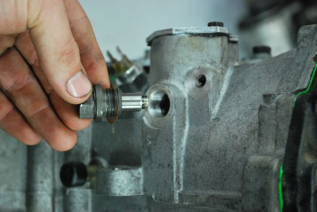
Step 4
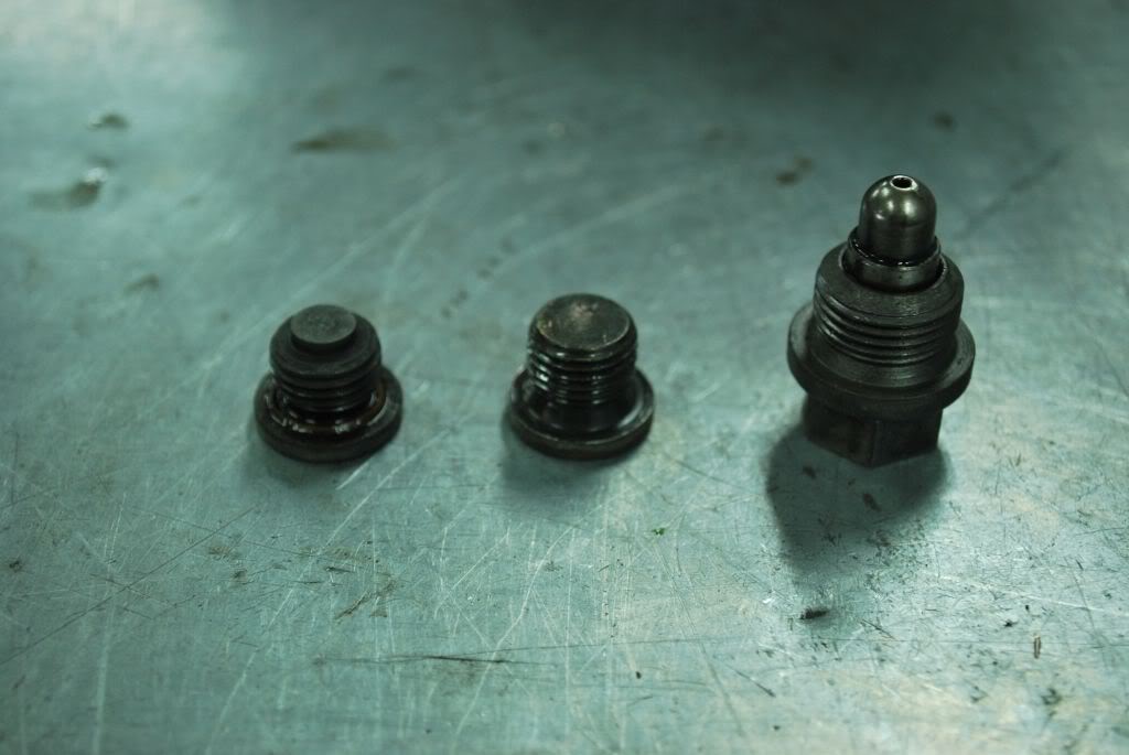
Remove the 17mm gear selector detent

Step 5
Remove the 3 10mm socket bolts, remove the gear selector plate

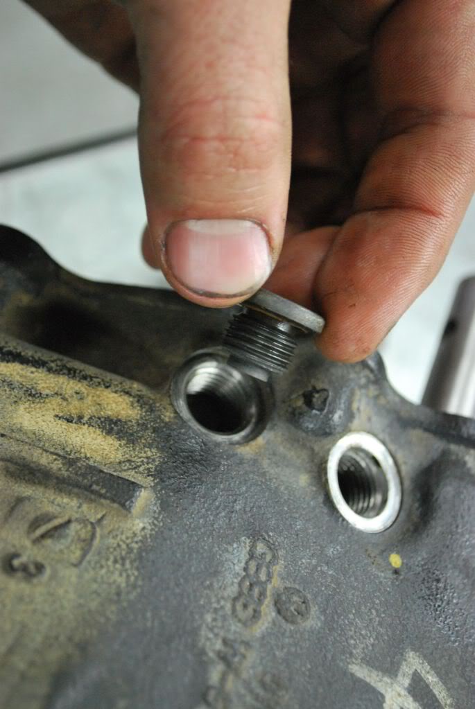
Step 6.Lock the input shaft and select a gear. THis will help lock the Pinion so that you can remove the triple square bolt Behind the Rear seal. Remove the triple square bolt.

Step 7
Now remove all the 6mm allen bolts holding on the rear housing. then tap the rear housing off with a drift. alternate sides with the drift until the housing is removed
Step 8
Remove the 17mm bolt on 5th gear

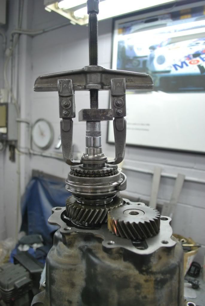
Step 9
Use a puller to remove the rear bearing race and part of the 5th gear assembly.
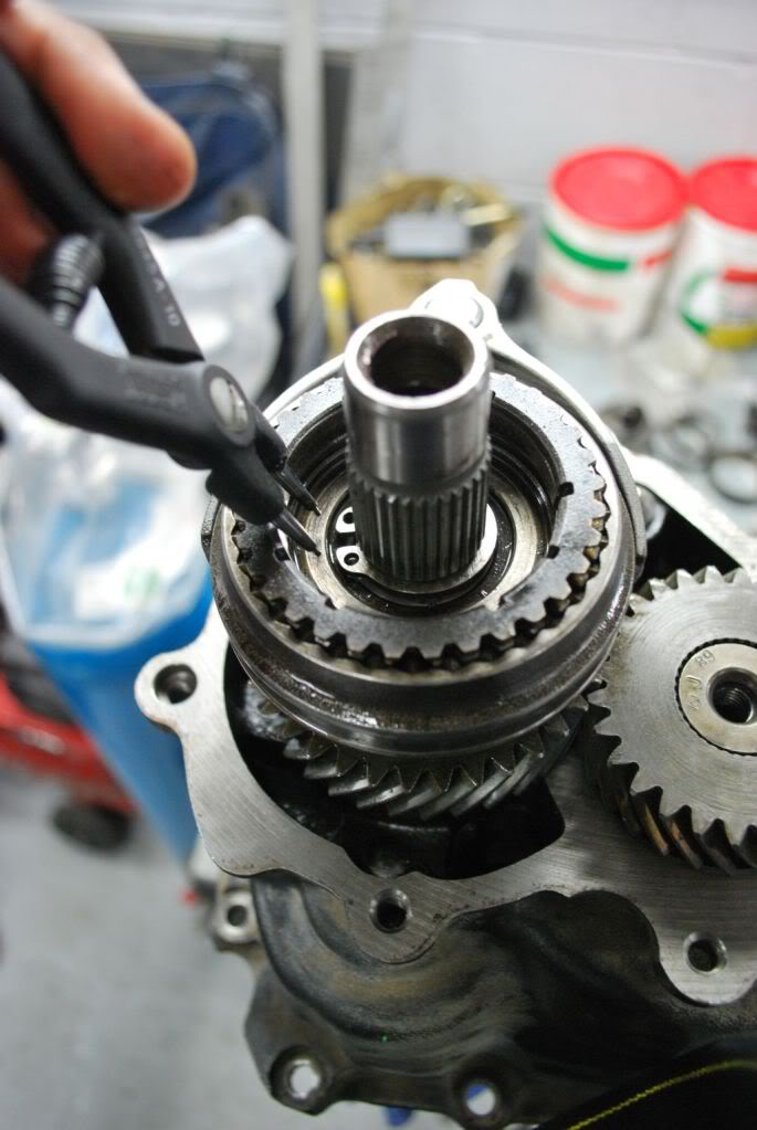
Step 10
Remove the circlip in the 5th gear assembly
Step 11.
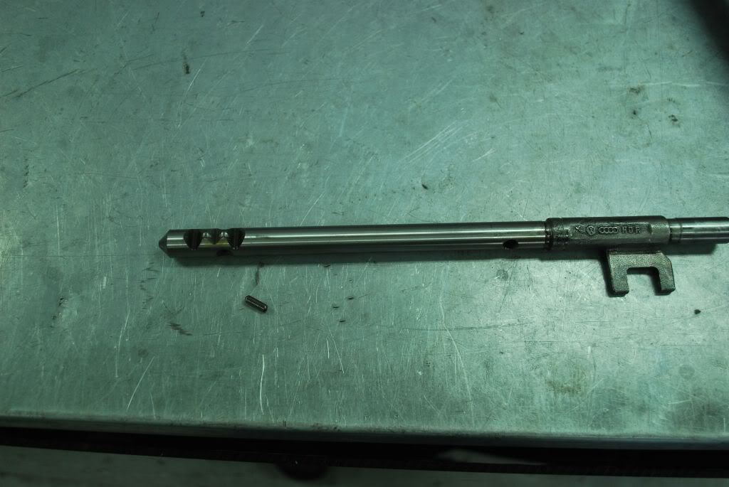
Next remove the 5th gear selector fork dowel with a punch.

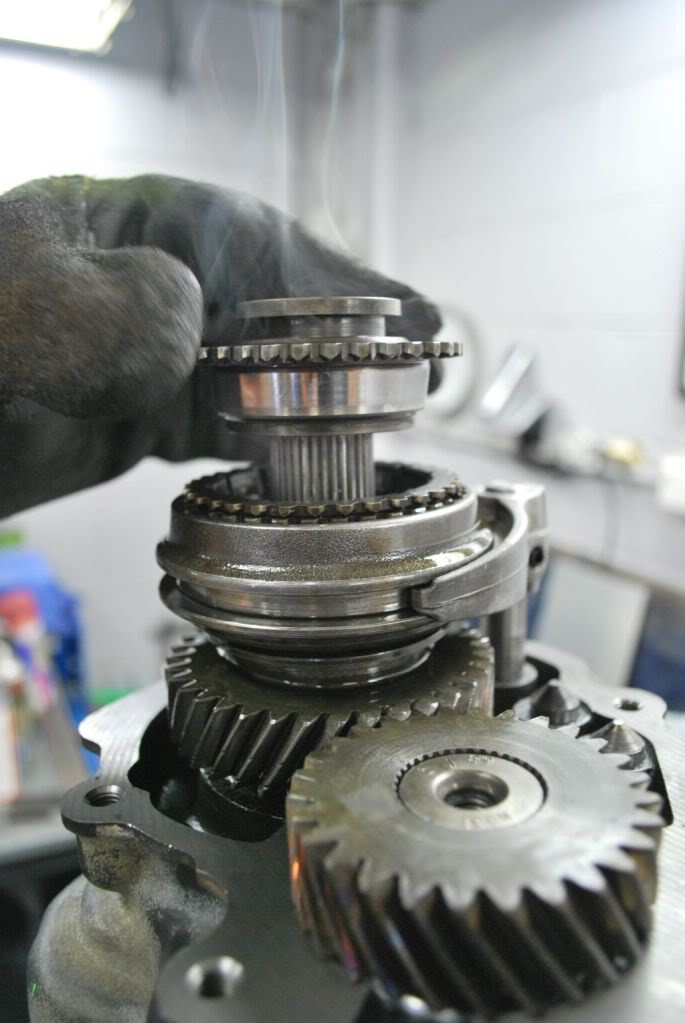
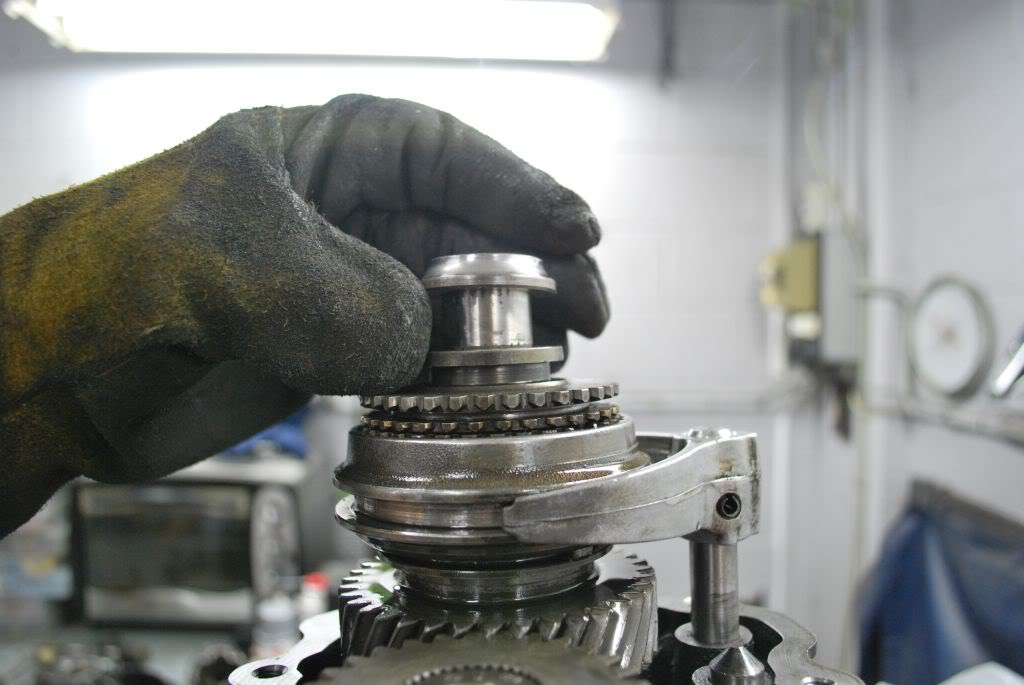
Step 12.
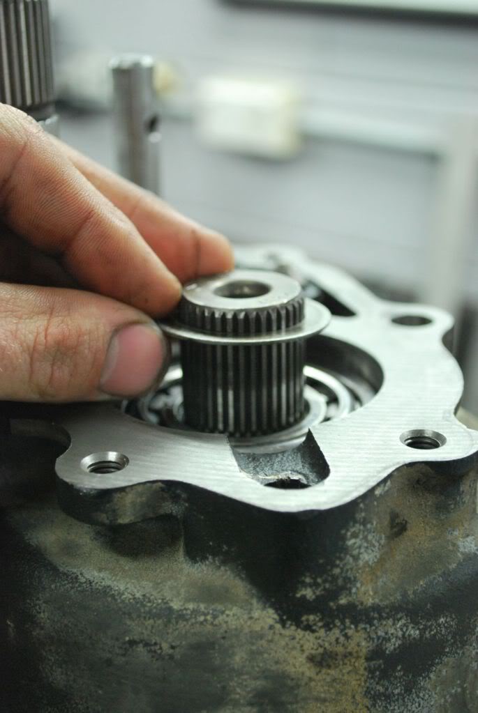
With a bit of coercing you can now remove 5th gear.

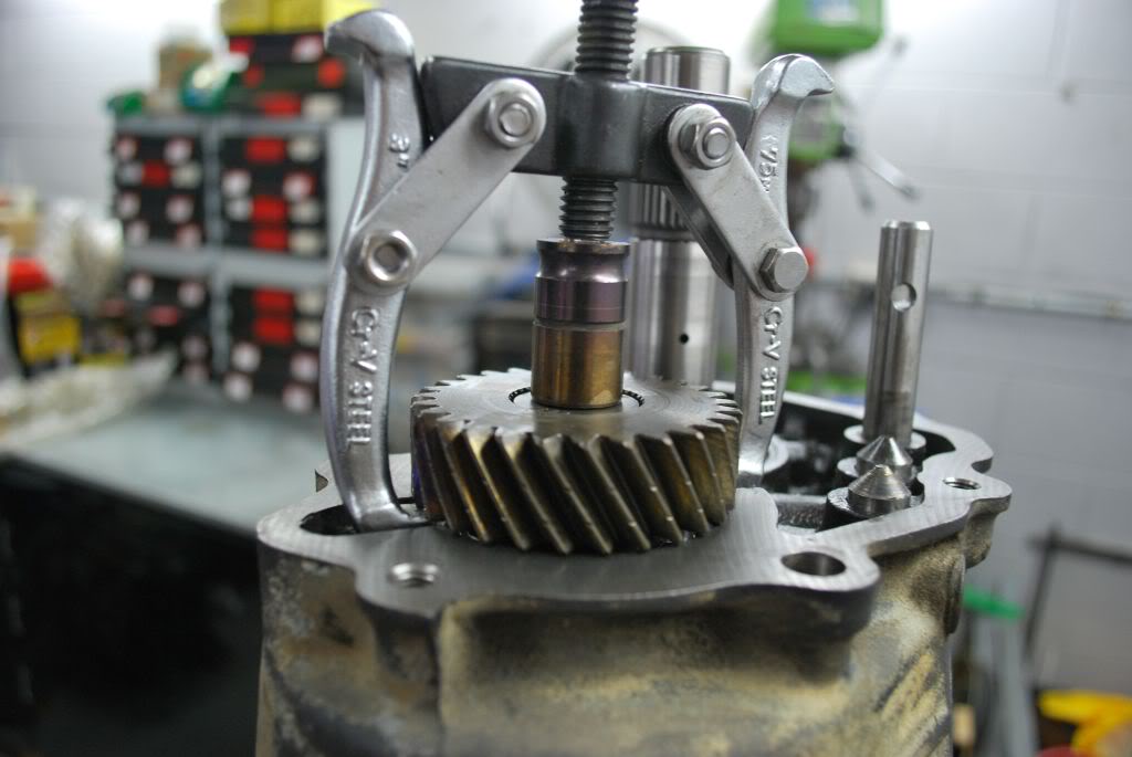
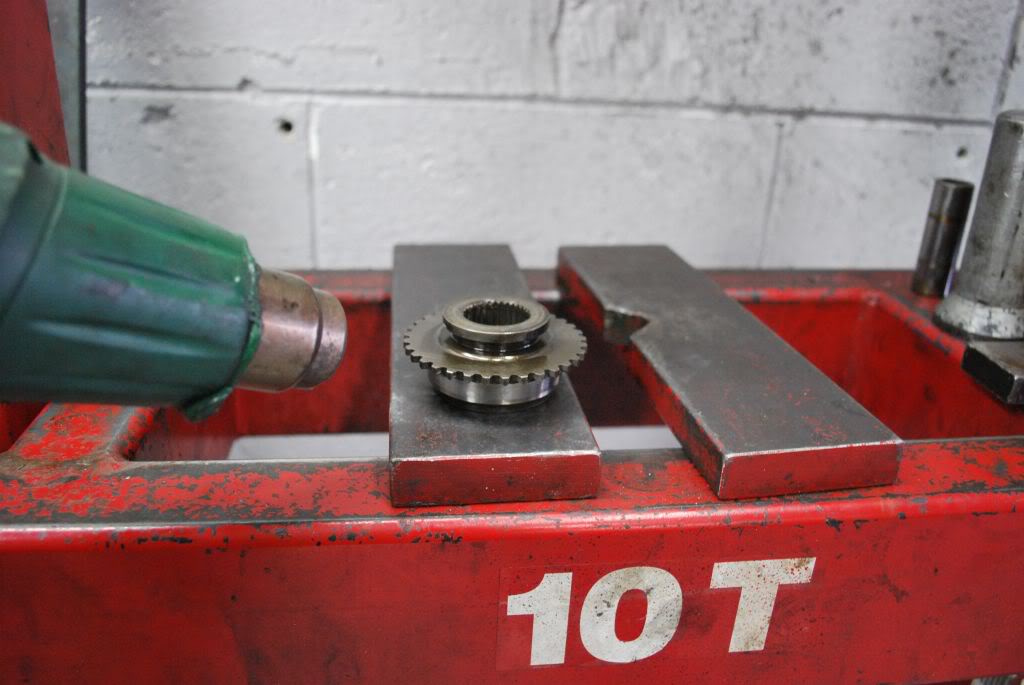
Step 13.
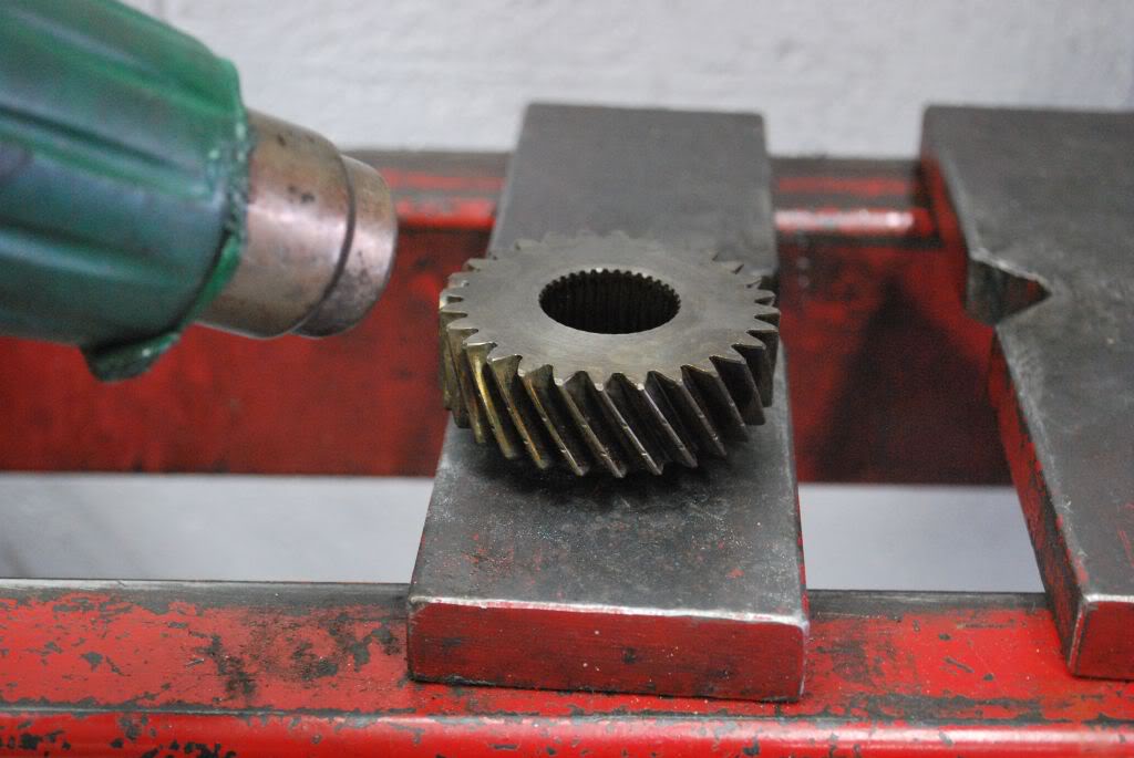
Use a 2 arm puller to remove the matched 5th gear. It is easier if you heat the gear up with hot air guns before removal
Step 14
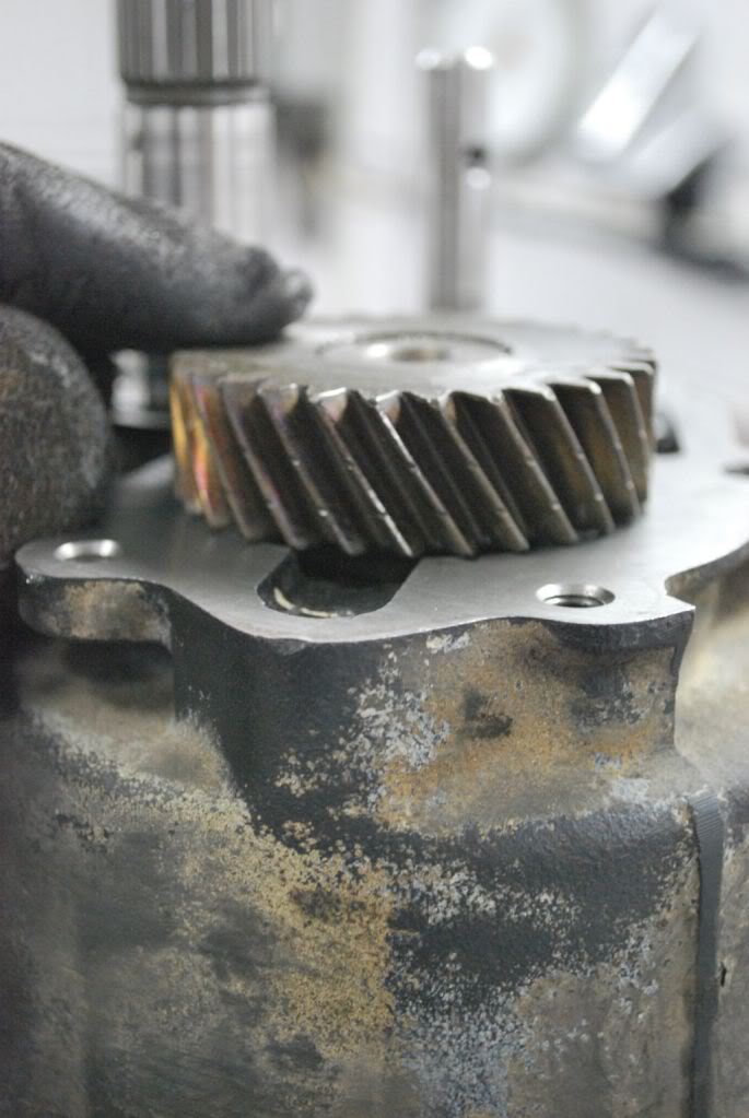
Remove the shim for 5th gear. you can see it below sitting atop the main shaft bearing.
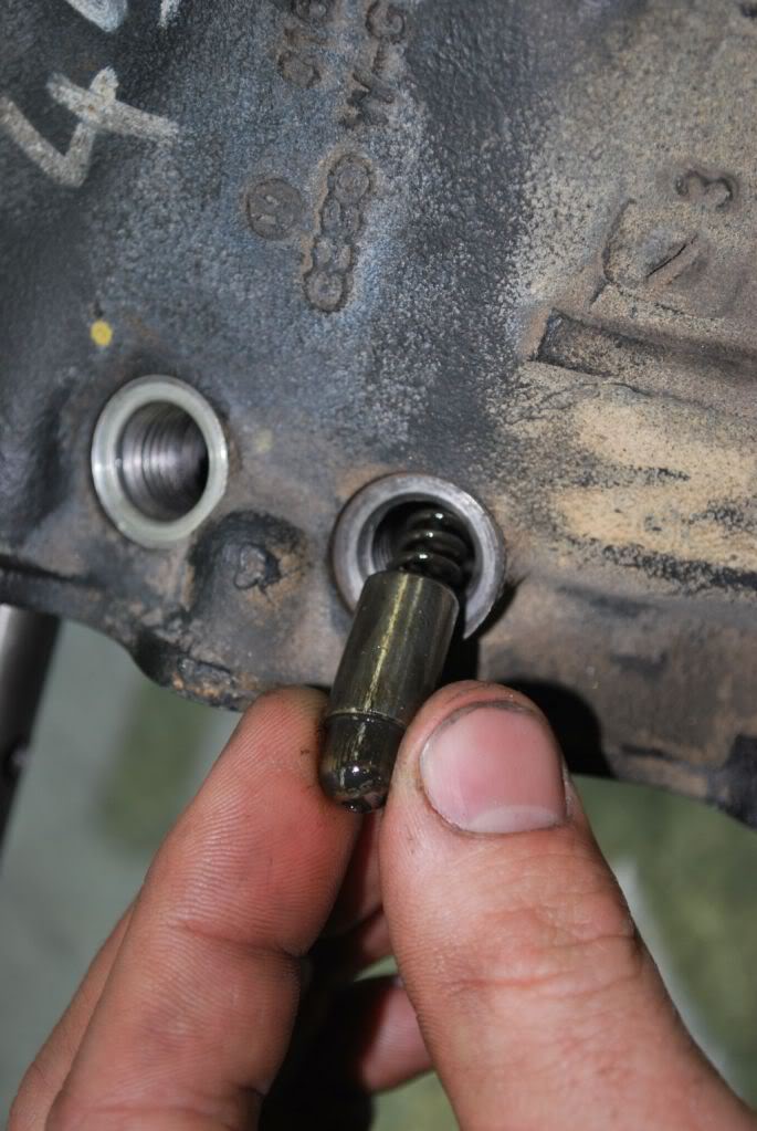
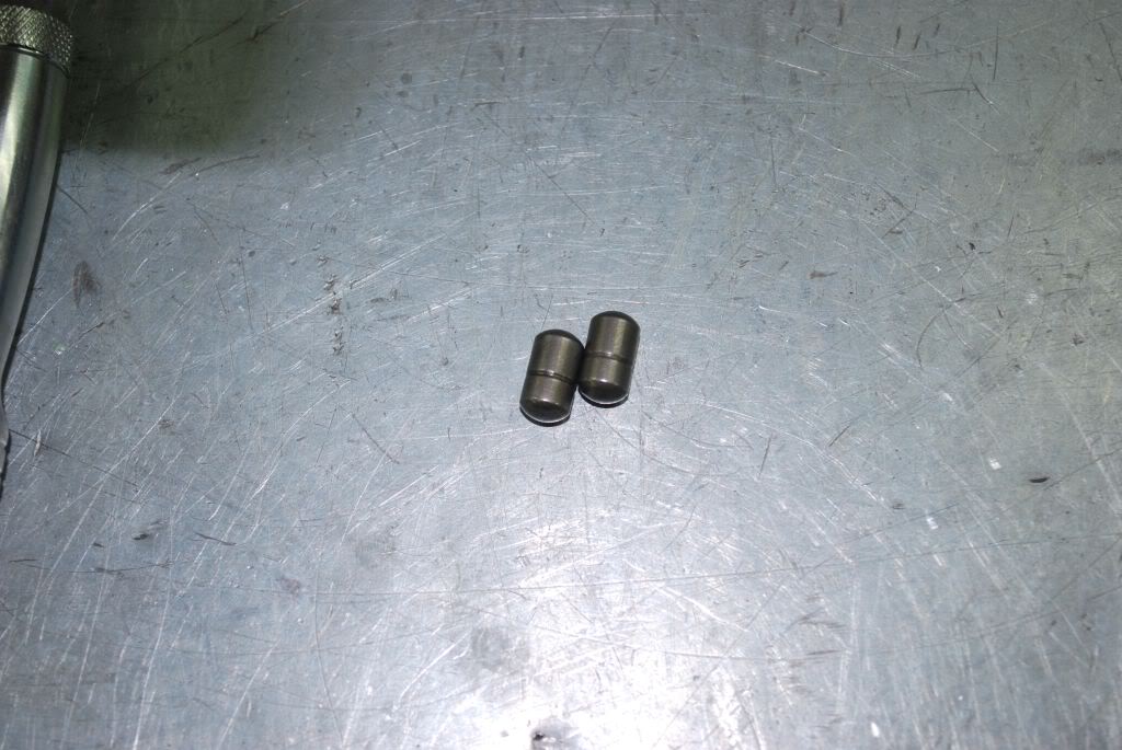
Step 15
Remove the 2 6mm stop bolts and the 17mm stop bolts and detents on the main carrier case
step 16
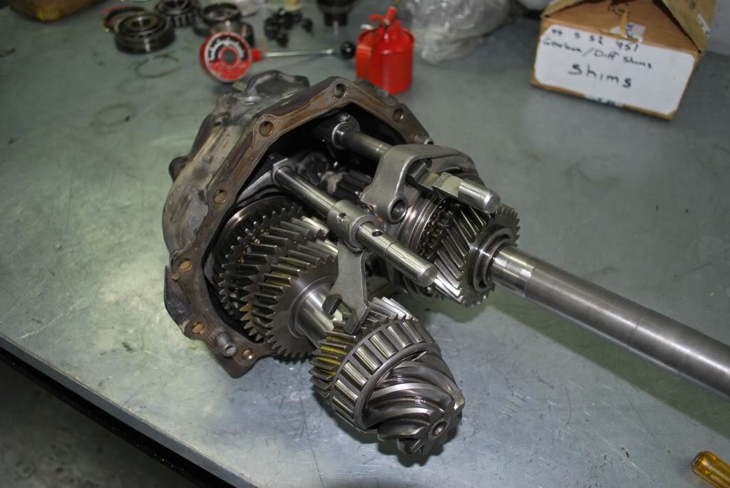
Now remove all of the 13mm bolts holding the main carrier to the diff carrier. Use a drift and tap both sides of the main carrier until it is loose from the diff housing. you can now remove the main carrier with the gearset.
Step 17
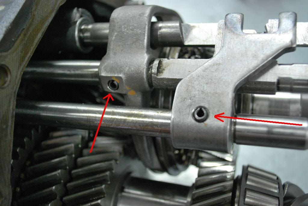
with a punch remove the dowel for 1st/2nd and for 3rd/4th.
Step 18
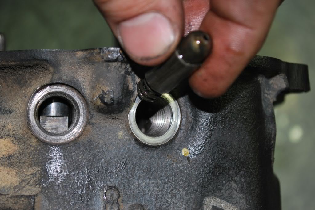
you can now remove 3rd/4th selector Rod. be careful though as there is a small locking detent which lives in the 3rd/4th selector Rod. when removing you will most likely hear it fall into the main carrier case. you will also find a detent and spring beneath the 3rd/4th selector rod
Step 19
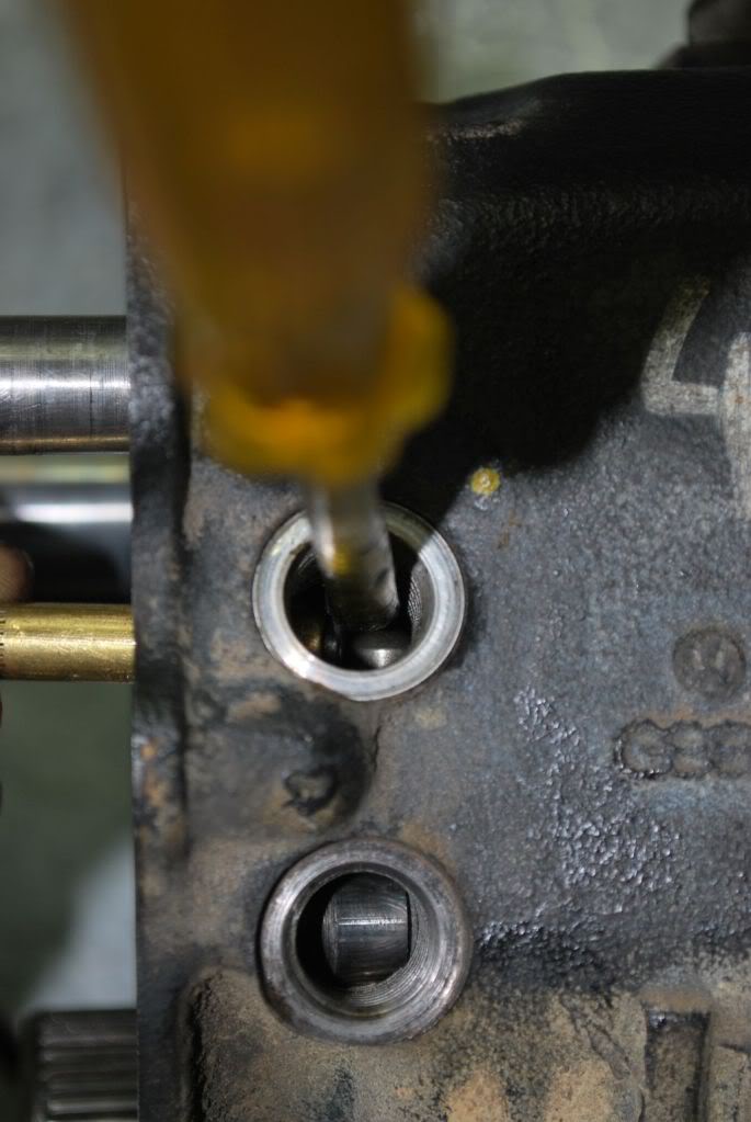
Remove selector Rod Locks with a magnet

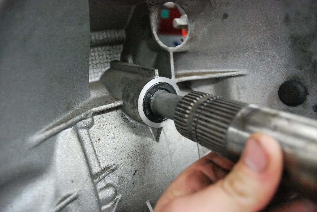
Step 20
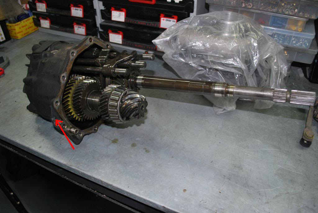
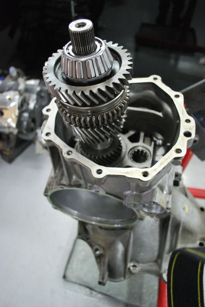
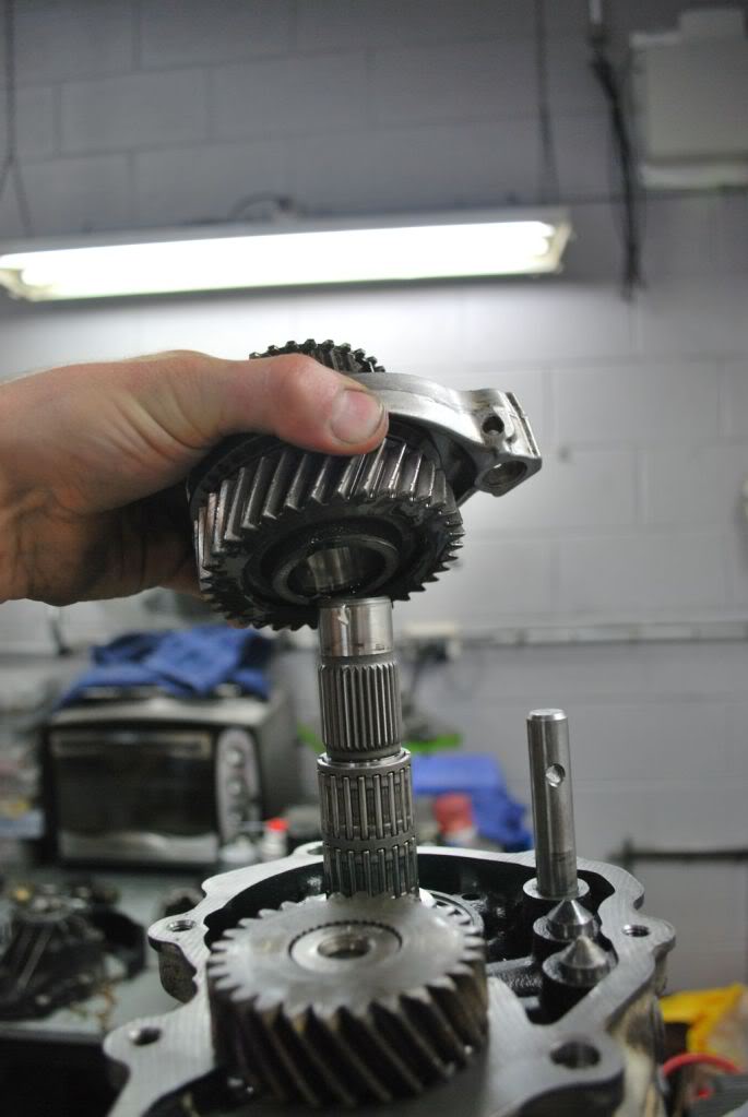
You can now move the pinion forward with 1st/2nd selector rod and now remove the input shaft

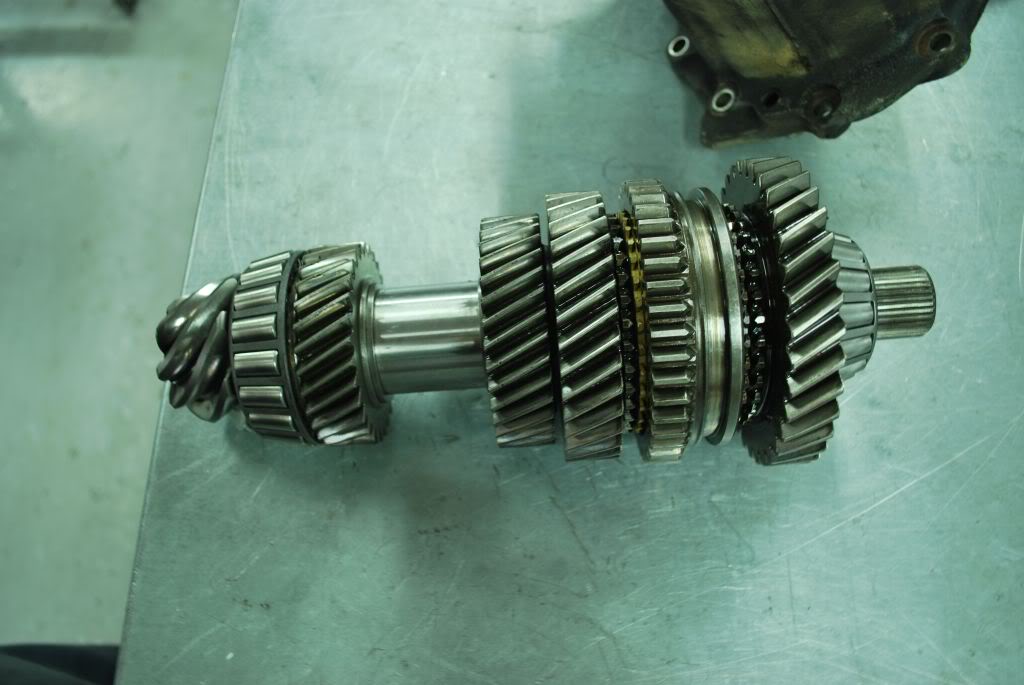
step 21
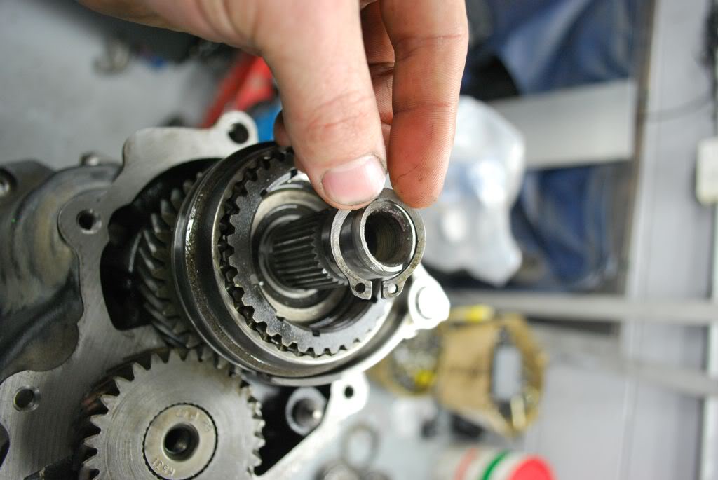
With the pinion removed you can now disassemble it if needed. You will need a press for this. you can see where the circlips are.
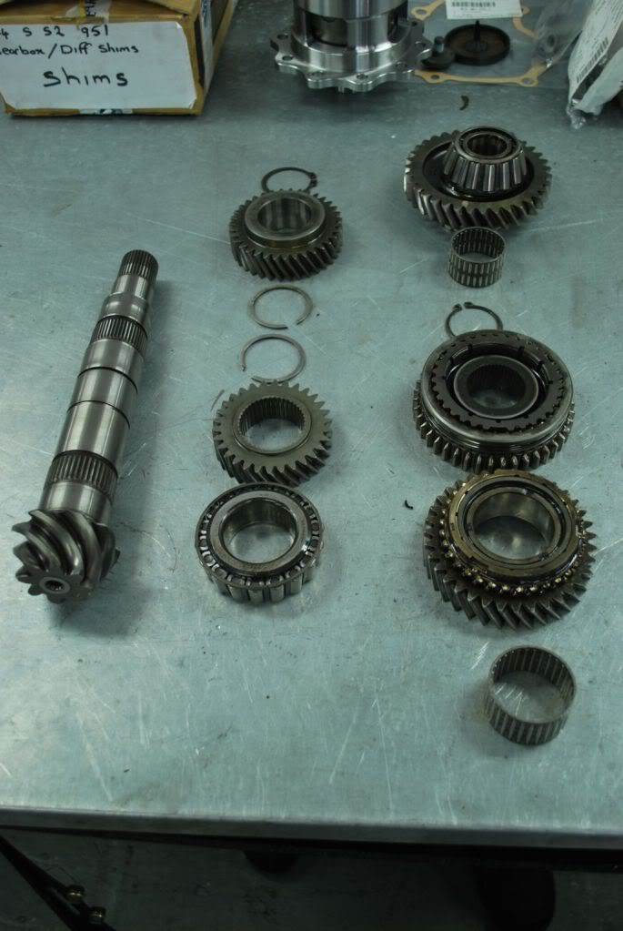
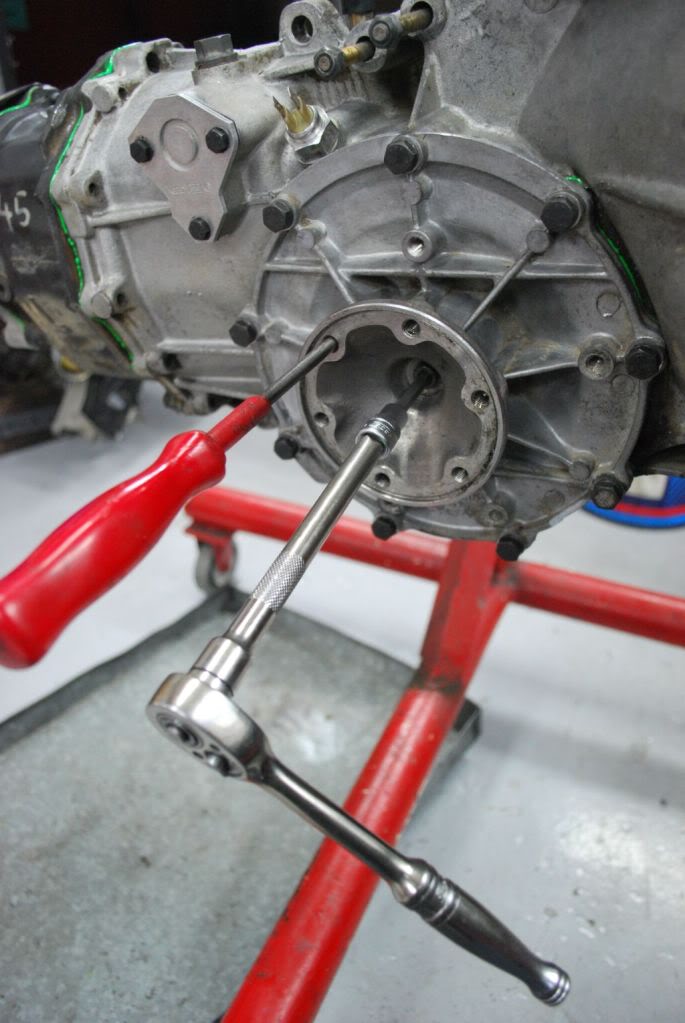
Step 22
Here is the Pinion assembled with new bearings ready to have the pinion preload set. Every time the bearings are replaced the preload will need to be rechecked and modified if necessary. Next photo is of the tools needed to assemble the 944 trans and set pinion preload, pinion depth and diff backlash
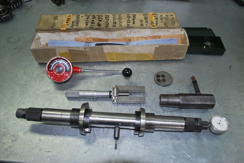
Step 23.
Setting preload. We use the original shims behind the bearing shells to first check pinion preload. remove old bearing shells and replace with the new ones.
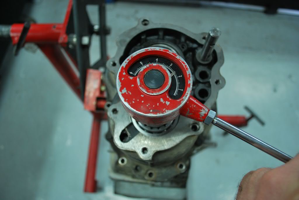
Step 24
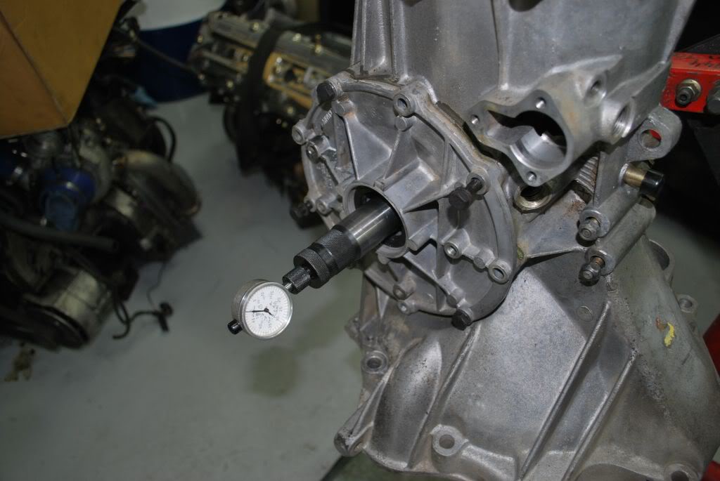
With the Pinion in place and main carrier torqued to the diff case(all bolts) you can now check Pinion preload with a torque gauge as shown. you turn the torque gauge until the Pinion is turning and then take the reading. We use 2.5NM as a good preload. Assemble the shims so that 2.5nm is reached. This may take a few attempts with different shims
So we step into the tear down
Step 1.
set the Gearbox up so that it can be worked on
Step 2
Lock the CV flange with a screw driver and remove the 6mm allen bolts
Step 3
With a screw driver puncture the rear seal and pry it out
Step 4
Remove the 17mm gear selector detent
Step 5
Remove the 3 10mm socket bolts, remove the gear selector plate
Step 6.Lock the input shaft and select a gear. THis will help lock the Pinion so that you can remove the triple square bolt Behind the Rear seal. Remove the triple square bolt.
Step 7
Now remove all the 6mm allen bolts holding on the rear housing. then tap the rear housing off with a drift. alternate sides with the drift until the housing is removed
Step 8
Remove the 17mm bolt on 5th gear
Step 9
Use a puller to remove the rear bearing race and part of the 5th gear assembly.
Step 10
Remove the circlip in the 5th gear assembly
Step 11.
Next remove the 5th gear selector fork dowel with a punch.
Step 12.
With a bit of coercing you can now remove 5th gear.
Step 13.
Use a 2 arm puller to remove the matched 5th gear. It is easier if you heat the gear up with hot air guns before removal
Step 14
Remove the shim for 5th gear. you can see it below sitting atop the main shaft bearing.
Step 15
Remove the 2 6mm stop bolts and the 17mm stop bolts and detents on the main carrier case
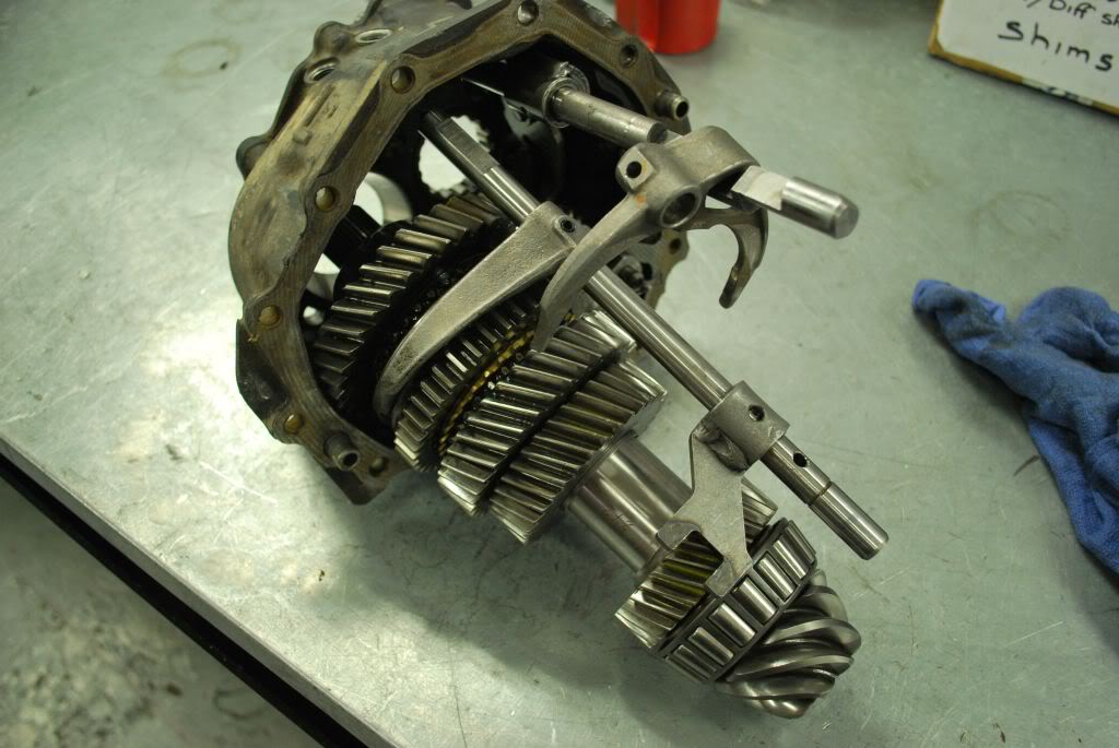
step 16
Now remove all of the 13mm bolts holding the main carrier to the diff carrier. Use a drift and tap both sides of the main carrier until it is loose from the diff housing. you can now remove the main carrier with the gearset.
Step 17
with a punch remove the dowel for 1st/2nd and for 3rd/4th.
Step 18
you can now remove 3rd/4th selector Rod. be careful though as there is a small locking detent which lives in the 3rd/4th selector Rod. when removing you will most likely hear it fall into the main carrier case. you will also find a detent and spring beneath the 3rd/4th selector rod
Step 19
Remove selector Rod Locks with a magnet
Step 20
You can now move the pinion forward with 1st/2nd selector rod and now remove the input shaft
step 21
With the pinion removed you can now disassemble it if needed. You will need a press for this. you can see where the circlips are.
Step 22
Here is the Pinion assembled with new bearings ready to have the pinion preload set. Every time the bearings are replaced the preload will need to be rechecked and modified if necessary. Next photo is of the tools needed to assemble the 944 trans and set pinion preload, pinion depth and diff backlash
Step 23.
Setting preload. We use the original shims behind the bearing shells to first check pinion preload. remove old bearing shells and replace with the new ones.
Step 24
With the Pinion in place and main carrier torqued to the diff case(all bolts) you can now check Pinion preload with a torque gauge as shown. you turn the torque gauge until the Pinion is turning and then take the reading. We use 2.5NM as a good preload. Assemble the shims so that 2.5nm is reached. This may take a few attempts with different shims
Last edited by JET951; 03-21-2012 at 05:45 AM.
 03-20-2012, 07:25 AM
#2
Drifting
Thread Starter
Step 25
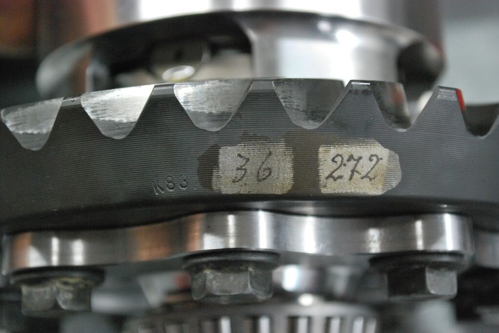
Next up is pinion depth.
The RO distance for the 944 S2 crownwheel and pinion is 59.65mm. to this we add the "quite running" number on the new crown wheel. In our case you can see here is 0.36mm.
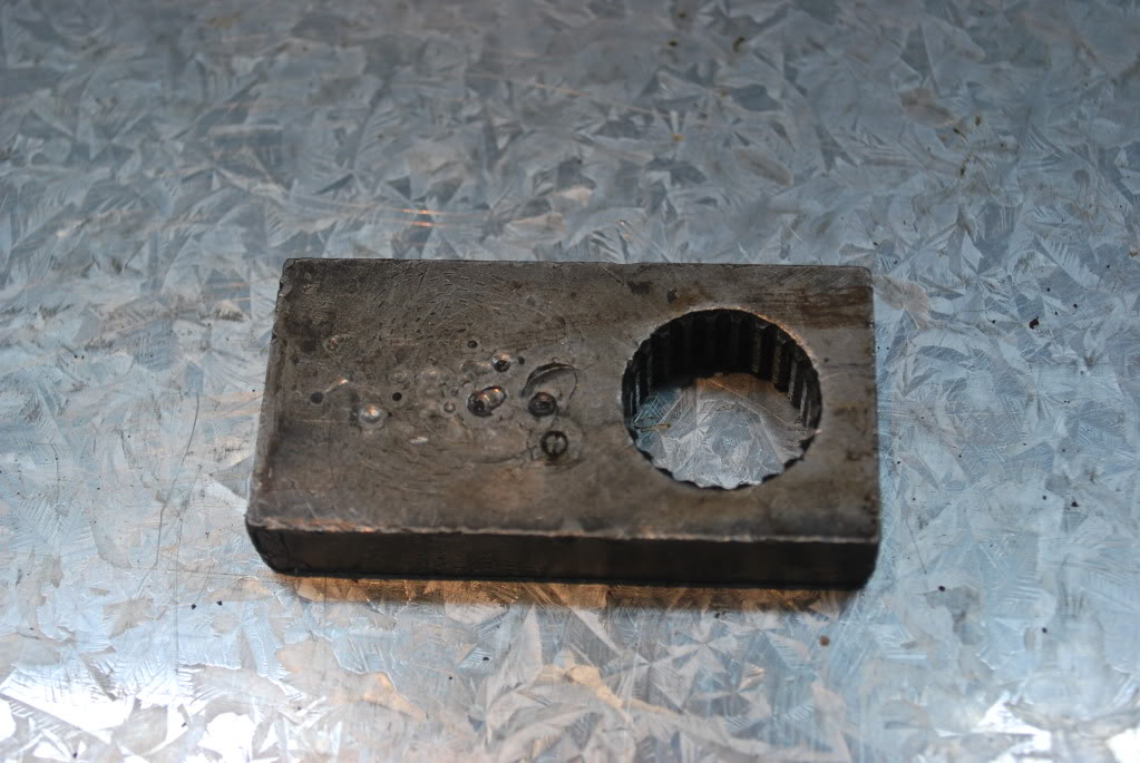
Step 26
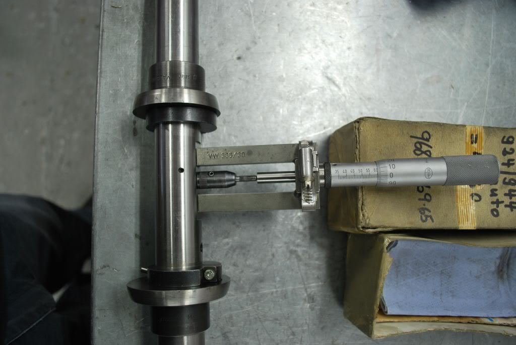
Here you can see us setting the pinion depth tool to our desired level. In our case the number was 60.01mm. We set the dial gauge at 2.5mm depth with the micrometer attached
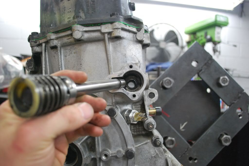
Step 27
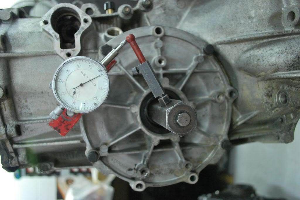
The pinion is in place and torqued. The Pinion also has a special tool(flat magnet) attached to it. This is so we can use the pinion depth tool against it and get an accurate reading.
The tool in placed where the diff would be placed and the diff case torque down. We now turn the tool until we read a maximum depth. We are trying to get as close to Zero as possible on the gauge.(which is our original 60.01 reading) Usually we get it within .01 of our desired quiet running distance. Remember when obtaining the Quiet running distance you will be moving the pinion forward or backwards. Considering the pinion preload is already set you need to remember if you remove shims from one side of the pinion to move it in a certain direction you must then add the exact same thickness shim(s) to the other side to keep your preload correct.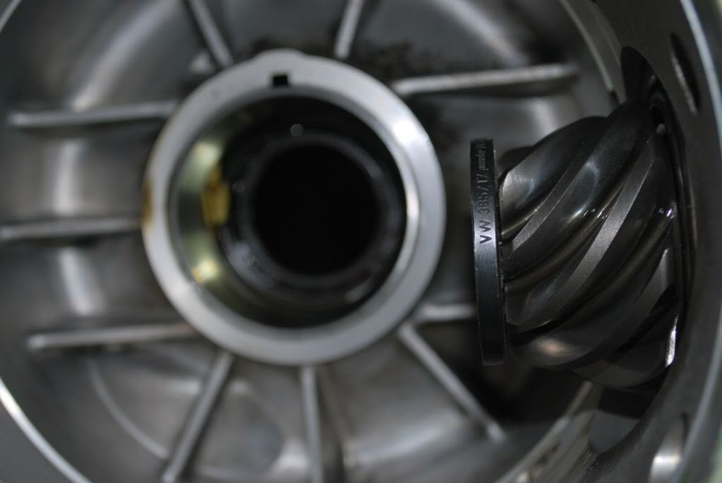
Step 28
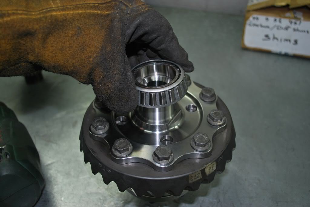
Assemble the diff with new bearings.(and in our case a new crown wheel and pinion, always use new crown wheel bolts) Its best to heat the Bearing with heat guns to aid in installation.
Step 29
Setting diff preload
you can now remove the Pinion again. And set the preload as you did with the Pinion. Using shims behind the new diff side shells Install the Diff and you can now set the diff preload to 2.5NM.
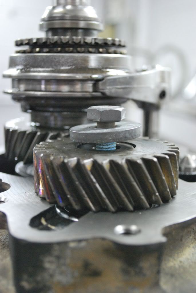
Step 30
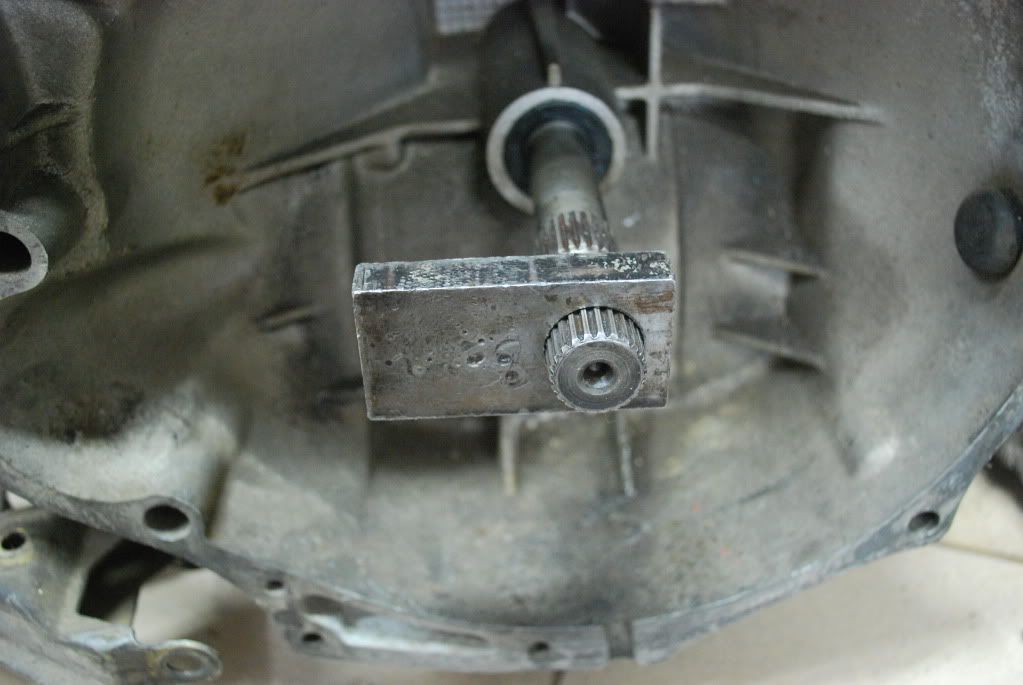
Setting Diff backlash.
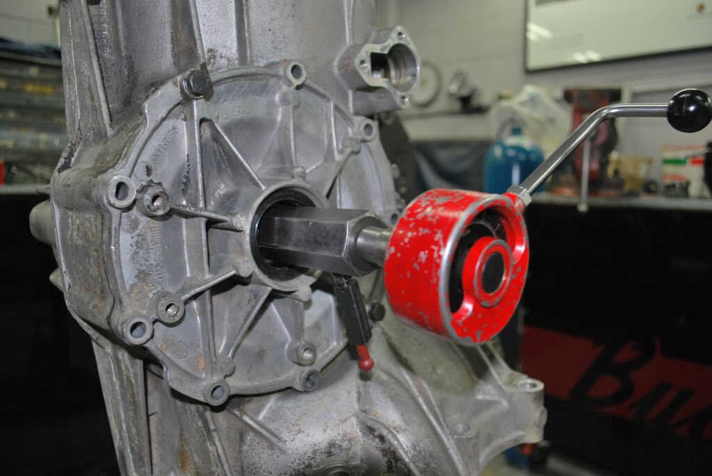
When setting diff backlash we are looking to obtain .10mm of movement on our dial gauge. this is a very small amount of movement so a dial gauge is needed. This is done with the Pinion torqued onto the diff housing with the main case(but without the gearset). The backlash tool is moved side to side to see the freeplay on the dial gauge. this will take some trial and error to get right.
Step 31
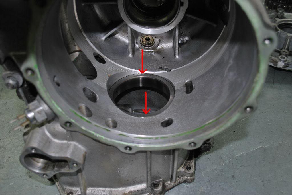
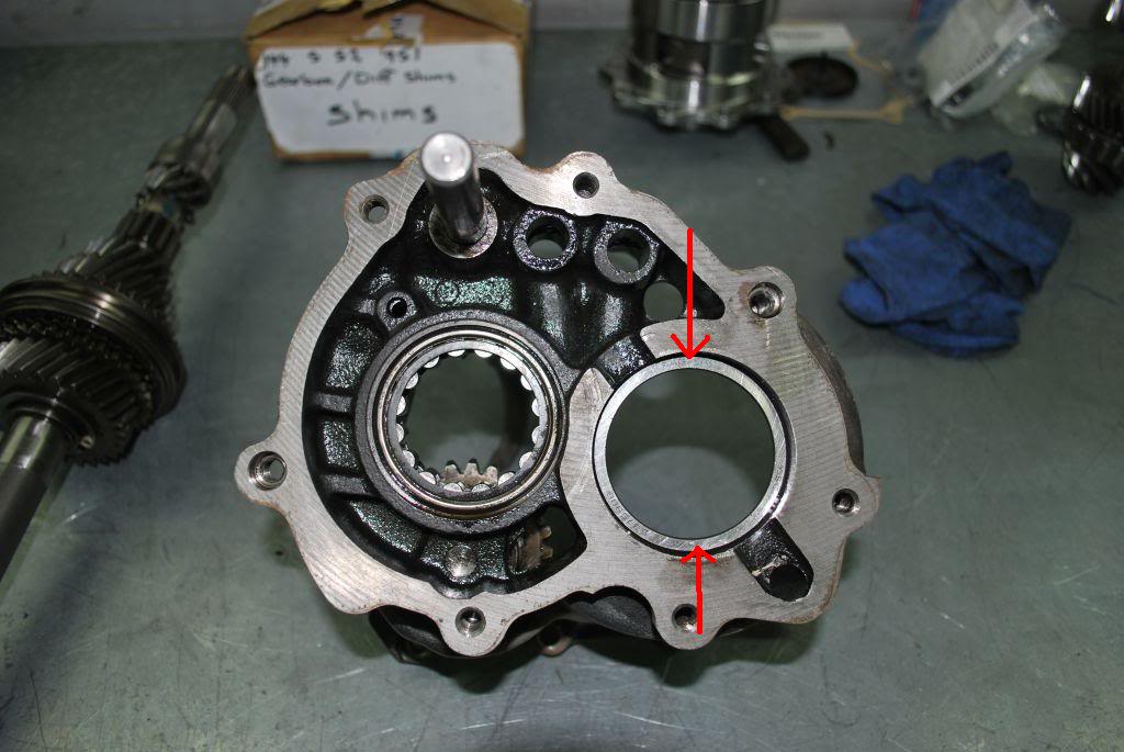
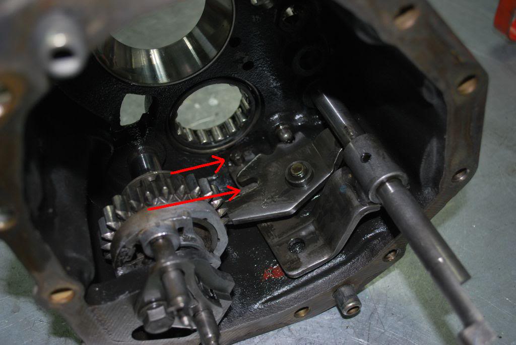
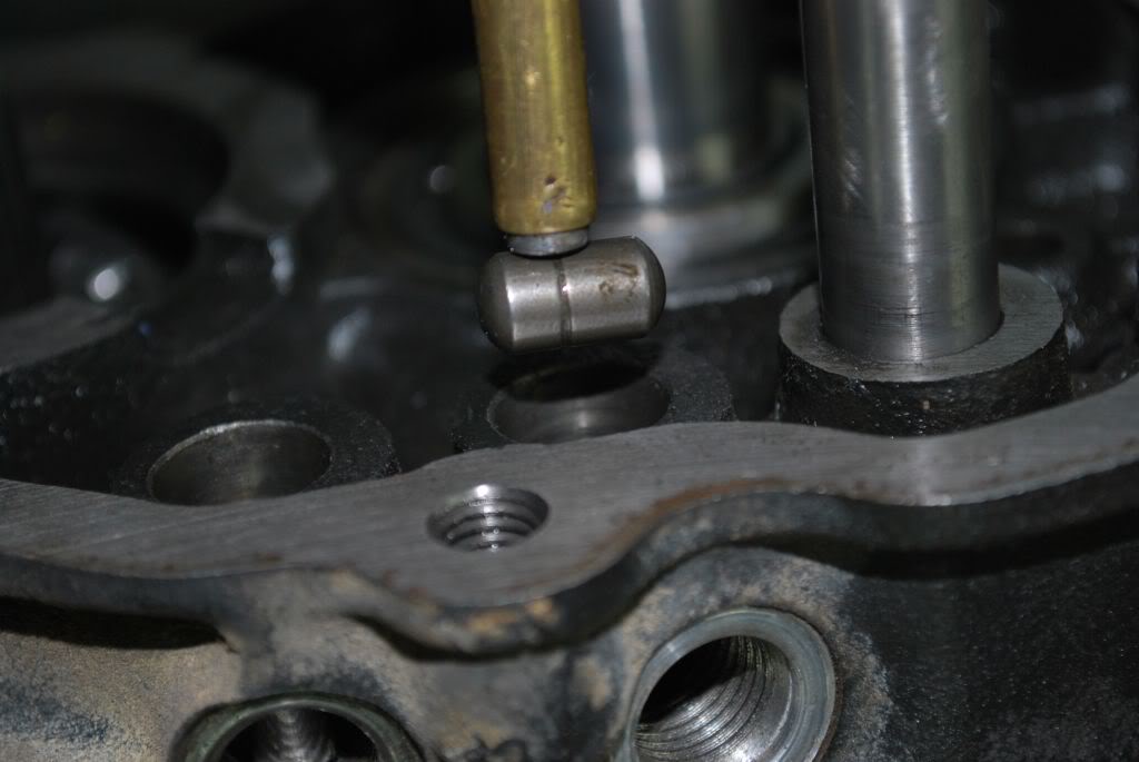
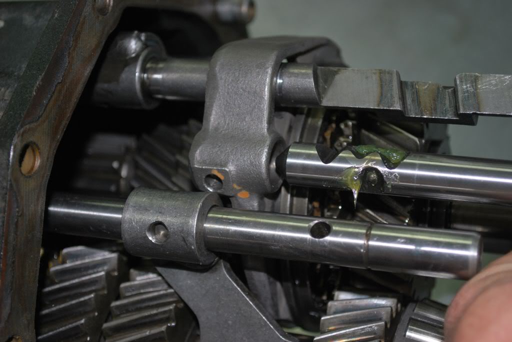
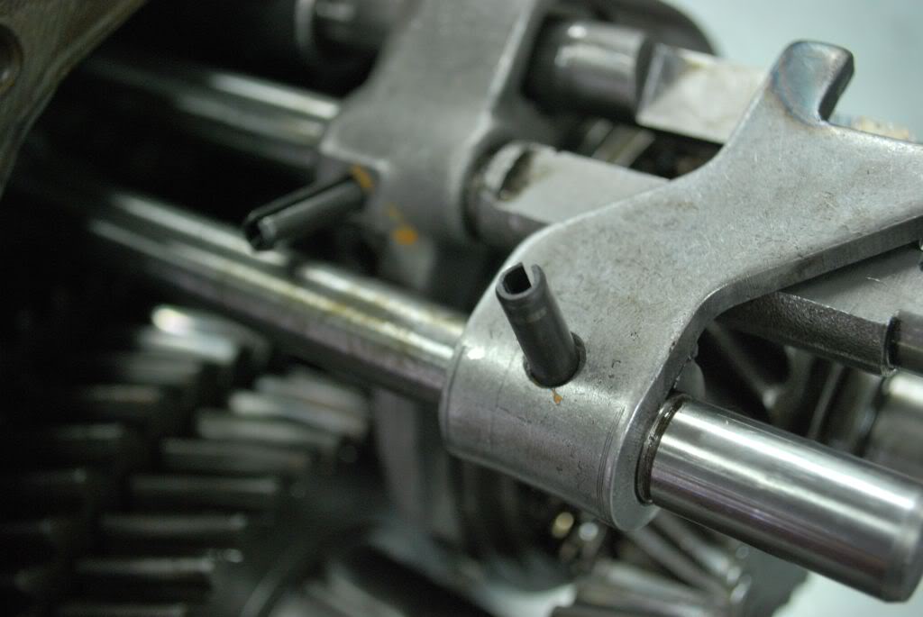
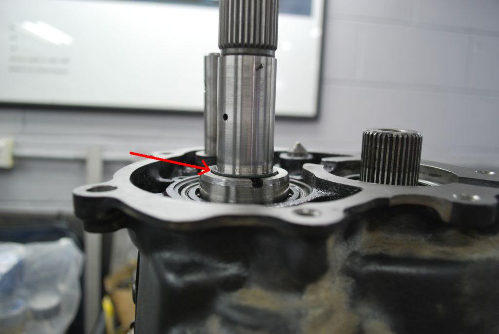
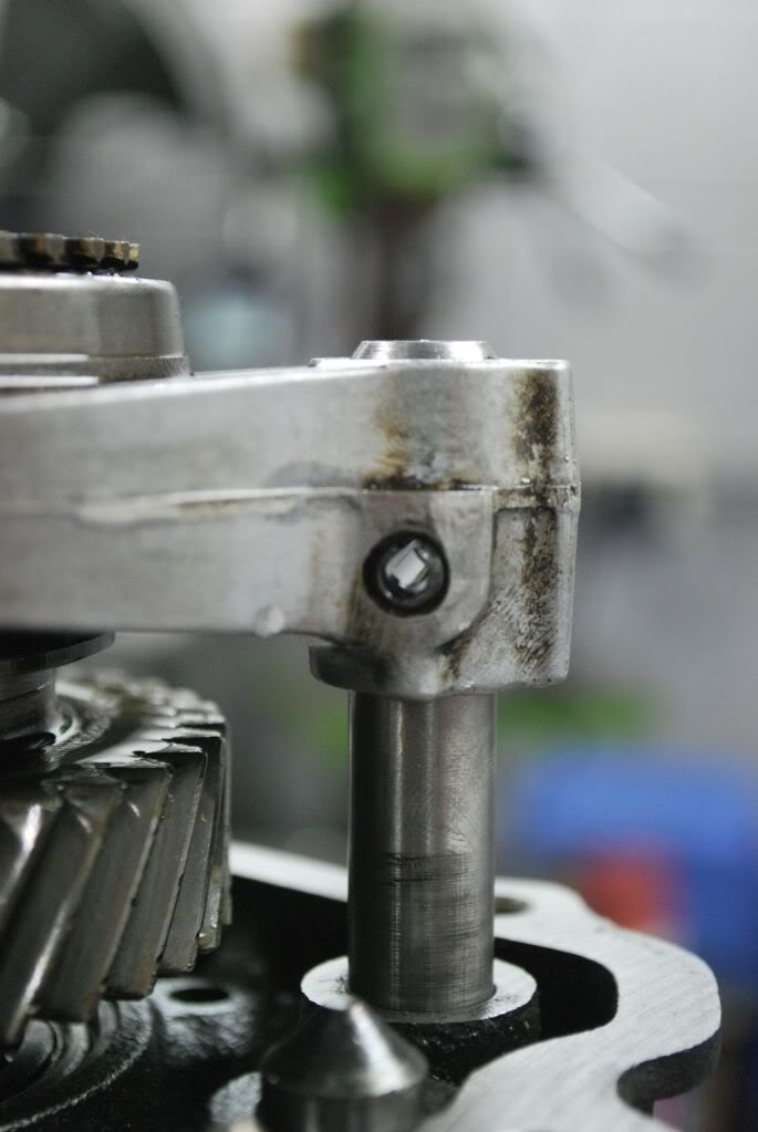
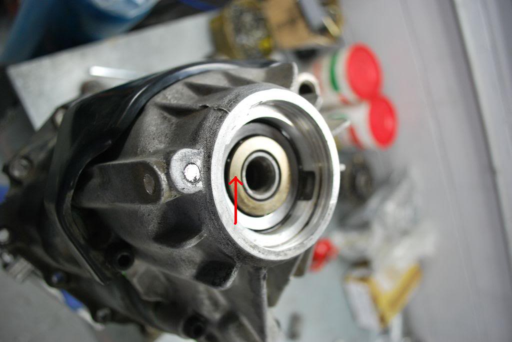
Time to re assessable the transmission. basic reverse of our disassemble. but a few things to look out for.
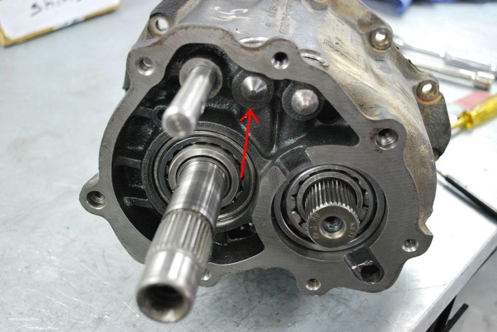
Make sure the pin(short arrow) is in the slot (big arrow) for reverse gear. other wise you will have problems.
Step 32
assemble Pinion with 1st/2nd selector shaft.
Step 33
Place locks in place and detent underneath 3rd/4th selector rod. Make sure the small lock is in place before 3rd/4th selector rod is installed. i use grease to hold it in place
Step 34
install Dowel for 1st/2nd and 3rd/4th selector Rods
Step 35
install stop bolts
Step 36
Put shims back on before 5th gear install
Step 37
Heat 5th gear and install.(it needs to be hot)
Step 38
Install 5th gear set assembly, install dowel, install circlip
Step 39
Heat 5th gear syncromesh ring and install, then heat inner bearing race and install
Step 40
Torque up 5th gear bolt to 70NM
Step 41
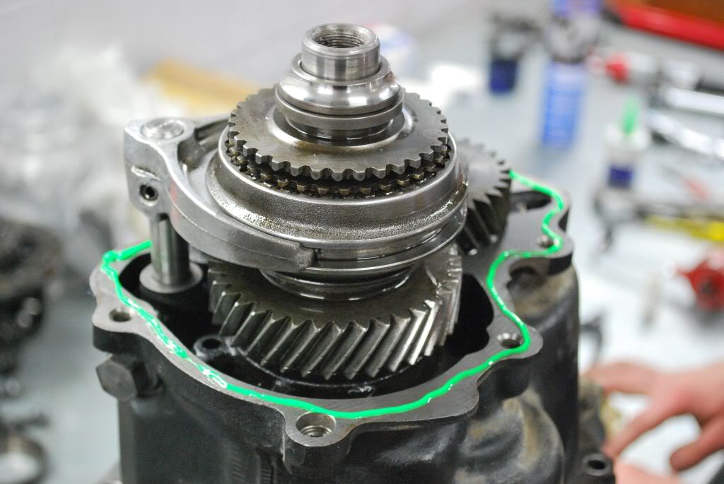
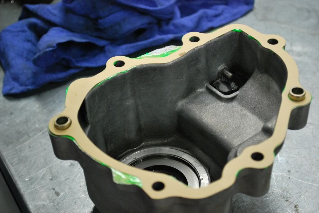
assemble with transmission sealant on gasket and torque together
Step 42
Heat up outer bearing race and install
Step 43
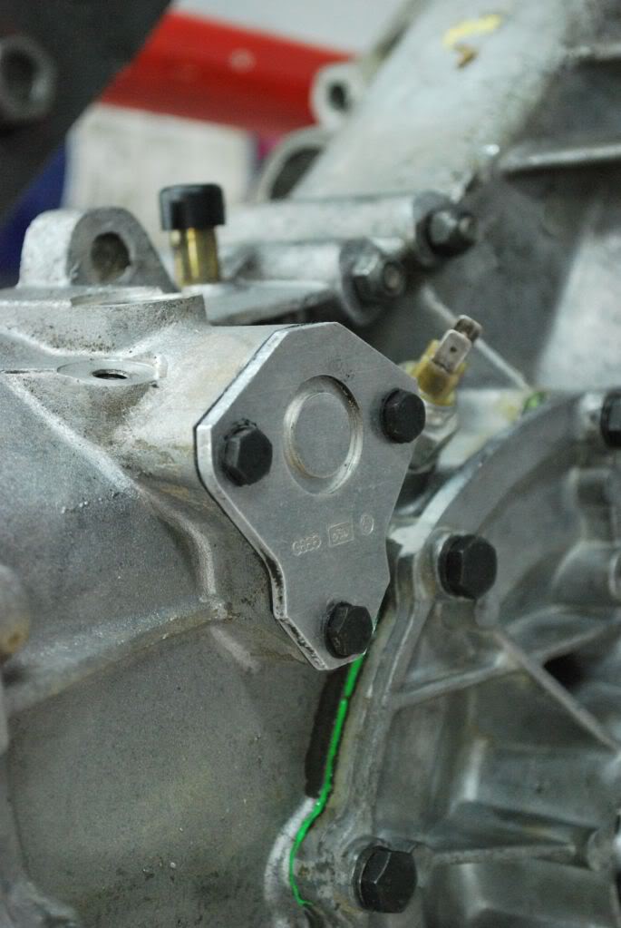
Remove input seal from diff case
Apply transmission sealant to between main case and diff case and torque down.
Step 44
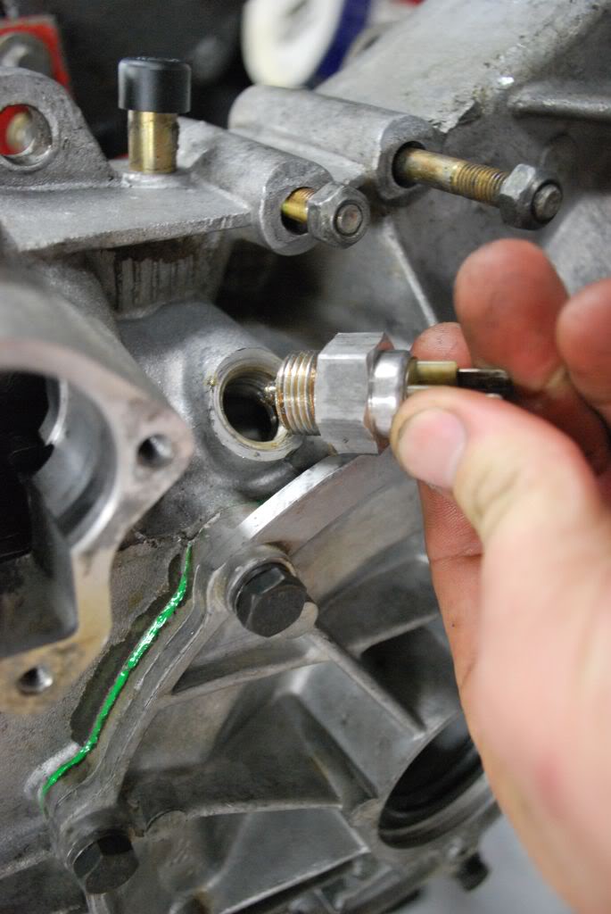
install reverse switch
Step 45
install selector, install selector plate, install top detent

Step 46
Install Rear seal, front seal and torque side flanges
Trans build now complete
regards
Sean
Next up is pinion depth.
The RO distance for the 944 S2 crownwheel and pinion is 59.65mm. to this we add the "quite running" number on the new crown wheel. In our case you can see here is 0.36mm.
Step 26
Here you can see us setting the pinion depth tool to our desired level. In our case the number was 60.01mm. We set the dial gauge at 2.5mm depth with the micrometer attached
Step 27
The pinion is in place and torqued. The Pinion also has a special tool(flat magnet) attached to it. This is so we can use the pinion depth tool against it and get an accurate reading.
The tool in placed where the diff would be placed and the diff case torque down. We now turn the tool until we read a maximum depth. We are trying to get as close to Zero as possible on the gauge.(which is our original 60.01 reading) Usually we get it within .01 of our desired quiet running distance. Remember when obtaining the Quiet running distance you will be moving the pinion forward or backwards. Considering the pinion preload is already set you need to remember if you remove shims from one side of the pinion to move it in a certain direction you must then add the exact same thickness shim(s) to the other side to keep your preload correct.
Step 28
Assemble the diff with new bearings.(and in our case a new crown wheel and pinion, always use new crown wheel bolts) Its best to heat the Bearing with heat guns to aid in installation.
Step 29
Setting diff preload
you can now remove the Pinion again. And set the preload as you did with the Pinion. Using shims behind the new diff side shells Install the Diff and you can now set the diff preload to 2.5NM.
Step 30
Setting Diff backlash.
When setting diff backlash we are looking to obtain .10mm of movement on our dial gauge. this is a very small amount of movement so a dial gauge is needed. This is done with the Pinion torqued onto the diff housing with the main case(but without the gearset). The backlash tool is moved side to side to see the freeplay on the dial gauge. this will take some trial and error to get right.
Step 31
Time to re assessable the transmission. basic reverse of our disassemble. but a few things to look out for.
Make sure the pin(short arrow) is in the slot (big arrow) for reverse gear. other wise you will have problems.
Step 32
assemble Pinion with 1st/2nd selector shaft.
Step 33
Place locks in place and detent underneath 3rd/4th selector rod. Make sure the small lock is in place before 3rd/4th selector rod is installed. i use grease to hold it in place
Step 34
install Dowel for 1st/2nd and 3rd/4th selector Rods
Step 35
install stop bolts
Step 36
Put shims back on before 5th gear install
Step 37
Heat 5th gear and install.(it needs to be hot)
Step 38
Install 5th gear set assembly, install dowel, install circlip
Step 39
Heat 5th gear syncromesh ring and install, then heat inner bearing race and install
Step 40
Torque up 5th gear bolt to 70NM
Step 41
assemble with transmission sealant on gasket and torque together
Step 42
Heat up outer bearing race and install
Step 43
Remove input seal from diff case
Apply transmission sealant to between main case and diff case and torque down.
Step 44
install reverse switch
Step 45
install selector, install selector plate, install top detent
Step 46
Install Rear seal, front seal and torque side flanges
Trans build now complete
regards
Sean
Last edited by JET951; 03-20-2012 at 05:54 PM.
 03-20-2012, 08:37 AM
#5
Rennlist Member
Thank you so much. Have been thinking about doing a aftermarket diff in my gear box, and this has given me a better understanding how the gearbox is put together and if i want to do it my self.
03-20-2012, 08:56 AM
#6
Race Car
Great write-up! Thanks much for posting that. A few questions for you.
1. The factory manual states 0.30mm should be added to the pinion shim thickness for pre-load, and 0.50mm should be added for carrier shim thickness for pre-load. My experience shows these numbers to be too thick by about 0.15 and 0.10mm, respecitvely. Curious as to your experience?
2. Of the three transaxles I have, one of them (came from an S2) has a shim/plate between the gear housing and rear housing that is probably 8mm thick. I have never seen any references to it elsewhere. I'm curious to know if you've seen this, and if so, any info as to whey itis there? FWIW, the rear housing on that transaxle is shorter by that much. The one that has it is the only one wihtout a cooling loop.
3. Any secrets for removing the triple-square bolt from the back of the input shaft? I eventually got them, but they are bears!
Trending Topics
03-20-2012, 09:40 AM
#8
Nordschleife Master
Most excellent write up Sean!
I have been back and forth with buying a used LSD box, or installing the LSD I have on hand to my gearbox... Guess I need to start searching for the special tools... as I am sure I will use them more than once!
the tans reinforcing plate is available, my understanding is it is used to stabilize the rear of the housing when horsepower is stepped up (V8 swaps, and GT40 replica builds)..
Here is just one source I have found over the years for them.. there are others!
http://www.texasperformanceconcepts....sionparts.html
I have been back and forth with buying a used LSD box, or installing the LSD I have on hand to my gearbox... Guess I need to start searching for the special tools... as I am sure I will use them more than once!
Great write-up! Thanks much for posting that. A few questions for you.
1. The factory manual states 0.30mm should be added to the pinion shim thickness for pre-load, and 0.50mm should be added for carrier shim thickness for pre-load. My experience shows these numbers to be too thick by about 0.15 and 0.10mm, respecitvely. Curious as to your experience?
2. Of the three transaxles I have, one of them (came from an S2) has a shim/plate between the gear housing and rear housing that is probably 8mm thick. I have never seen any references to it elsewhere. I'm curious to know if you've seen this, and if so, any info as to whey itis there? FWIW, the rear housing on that transaxle is shorter by that much. The one that has it is the only one wihtout a cooling loop.
3. Any secrets for removing the triple-square bolt from the back of the input shaft? I eventually got them, but they are bears!
1. The factory manual states 0.30mm should be added to the pinion shim thickness for pre-load, and 0.50mm should be added for carrier shim thickness for pre-load. My experience shows these numbers to be too thick by about 0.15 and 0.10mm, respecitvely. Curious as to your experience?
2. Of the three transaxles I have, one of them (came from an S2) has a shim/plate between the gear housing and rear housing that is probably 8mm thick. I have never seen any references to it elsewhere. I'm curious to know if you've seen this, and if so, any info as to whey itis there? FWIW, the rear housing on that transaxle is shorter by that much. The one that has it is the only one wihtout a cooling loop.
3. Any secrets for removing the triple-square bolt from the back of the input shaft? I eventually got them, but they are bears!
Here is just one source I have found over the years for them.. there are others!
http://www.texasperformanceconcepts....sionparts.html
Last edited by JohnKoaWood; 03-20-2012 at 01:45 PM.
 03-20-2012, 10:51 AM
#11
Race Car
Thanks, John! Had never seen that before. Probably won't need it for my mild SP3 car, but at least I know what it is.
03-20-2012, 12:02 PM
#14
Rennlist Member