When you click on links to various merchants on this site and make a purchase, this can result in this site earning a commission. Affiliate programs and affiliations include, but are not limited to, the eBay Partner Network.
I'm trying to find out what current supply I will need for my 8 Beru coil-on-plug units, from a Porsche Cayenne.
I found this data from in an article on the development of the Cayenne coils.
Beru Coil-On-Plug Data
Primary current [A] 9 15
Current-rise time [ms] 1.75 2.4
Secondary voltage [kV] 1 MOhm // 25 pF 26 31
Energy data (secondary load,
1000 V Zener to ISO 6518-2)
Spark duration [ms] 1.7 1.85
Spark current [mA] 60 80
Spark energy [mJ] 45 65
I don't know why they have 2 columns of data for each value?
I just want to know what current is required to feed the 8 coils in service?
Electrical gurus, please?
I see no one has had a shot at this, so I will have a go. I think the two columns of data might be max and min acceptable values. I tried to reconcile the spark voltage, current and energy, but the simple calculation doesn�t work. Must be lots of losses somewhere in the system. What I would say is that the primary current maximum of 15A as the number you should be able to provide. Sure, there are 8 of them, but they will never fire together, and with a very minimal duty cycle, I would say that being able to provide 15A to the sum of all COP�s
I see no one has had a shot at this, so I will have a go. I think the two columns of data might be max and min acceptable values. I tried to reconcile the spark voltage, current and energy, but the simple calculation doesn�t work. Must be lots of losses somewhere in the system. What I would say is that the primary current maximum of 15A as the number you should be able to provide. Sure, there are 8 of them, but they will never fire together, and with a very minimal duty cycle, I would say that being able to provide 15A to the sum of all COP�s
Albin
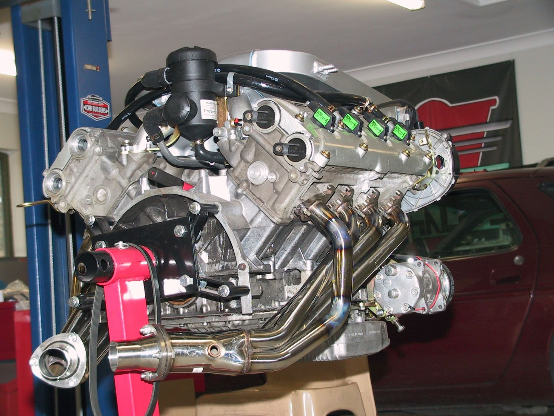
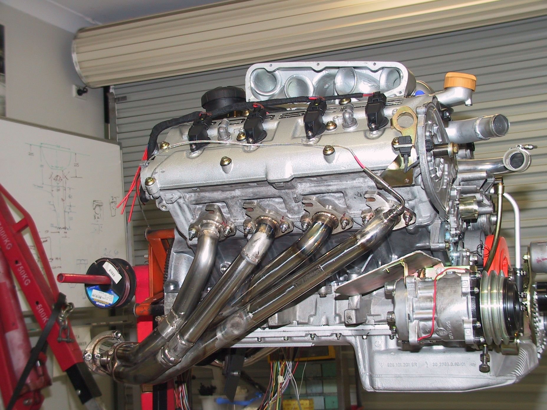
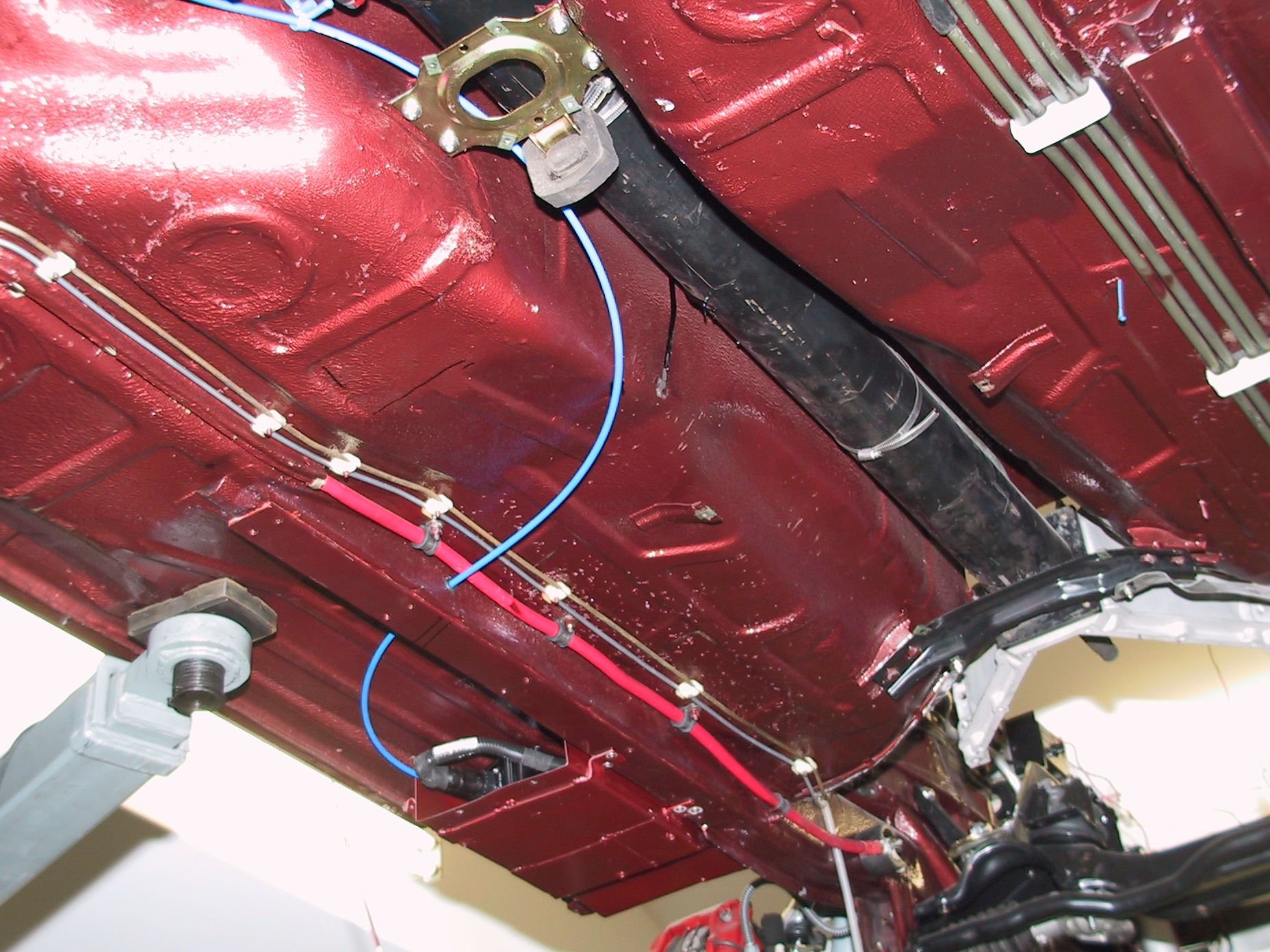
I've decided to go for 15 amp /coil system as I have the capacity and it's easy at this stage but not later!. I bought a 120 amp solid state relay [ouch] to feed the coils. 4 coil power wires join at the rear of each head, then 2 larger wires go into the foot-well to the SSR. Earths go into the valley to the old throttle body mounts.
Link EMS advised me to run all 8 earths there and NOT to take any back to the EMS unit.
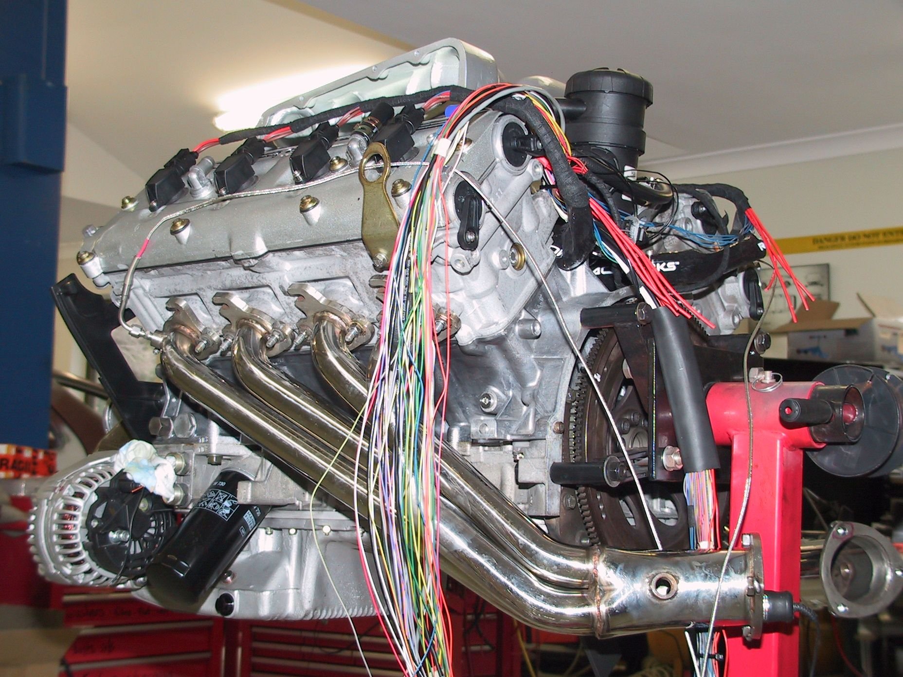
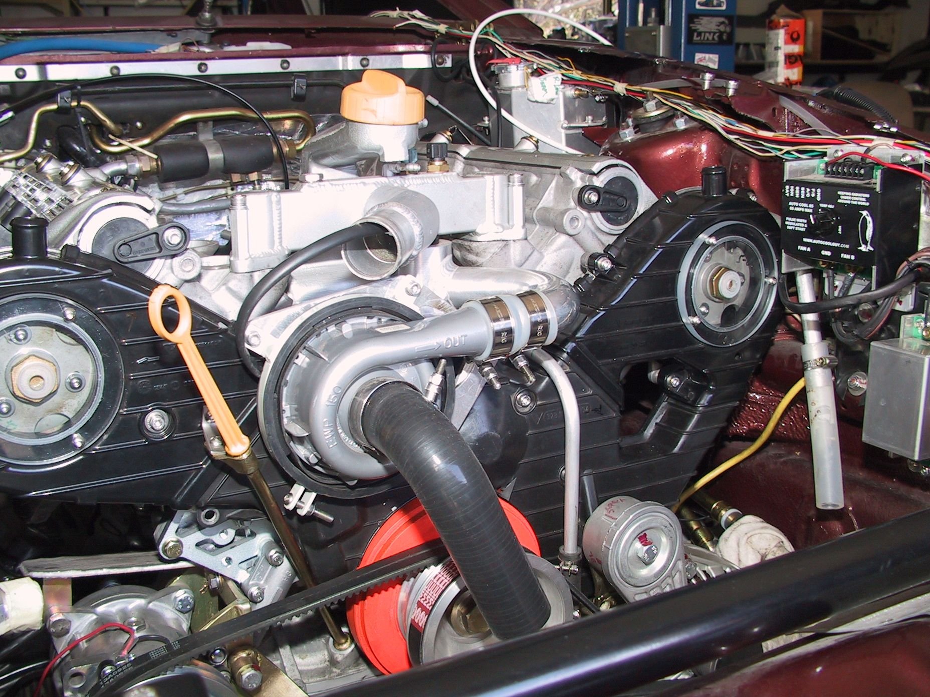
Engine now all sealed up, time for some serious wiring before it's final fit into the chassis.
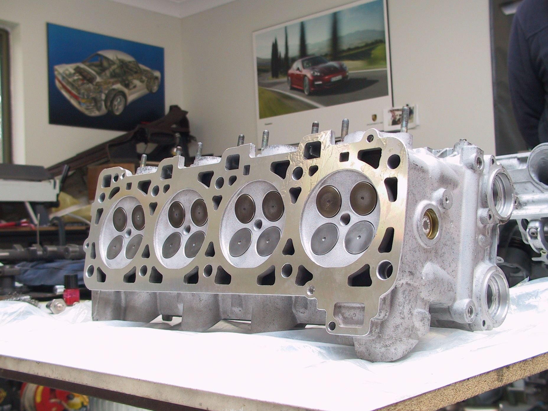
Heads back from rebuild Thermal disk in welch plug. If overheated, disk drops out. Tested for flat, twist, bend, hardness and pressure. New K-lined exhaust guides. Masses of wiring, plus header mods for RHD More wiring
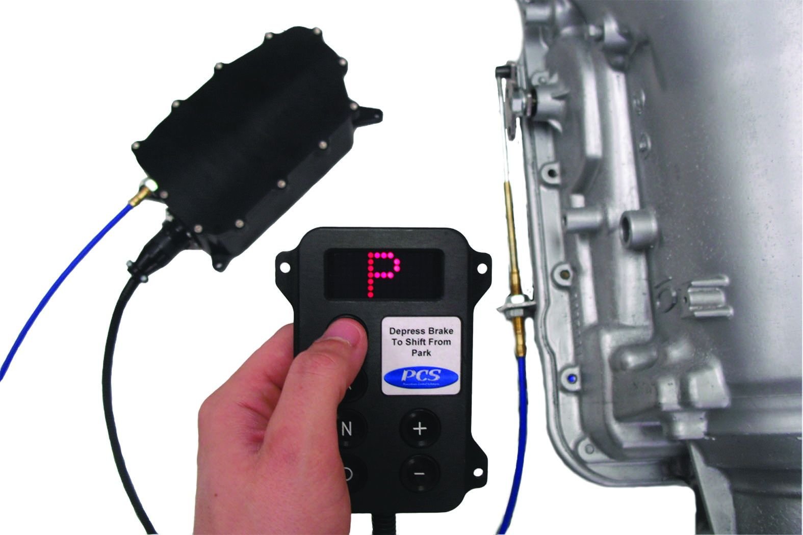
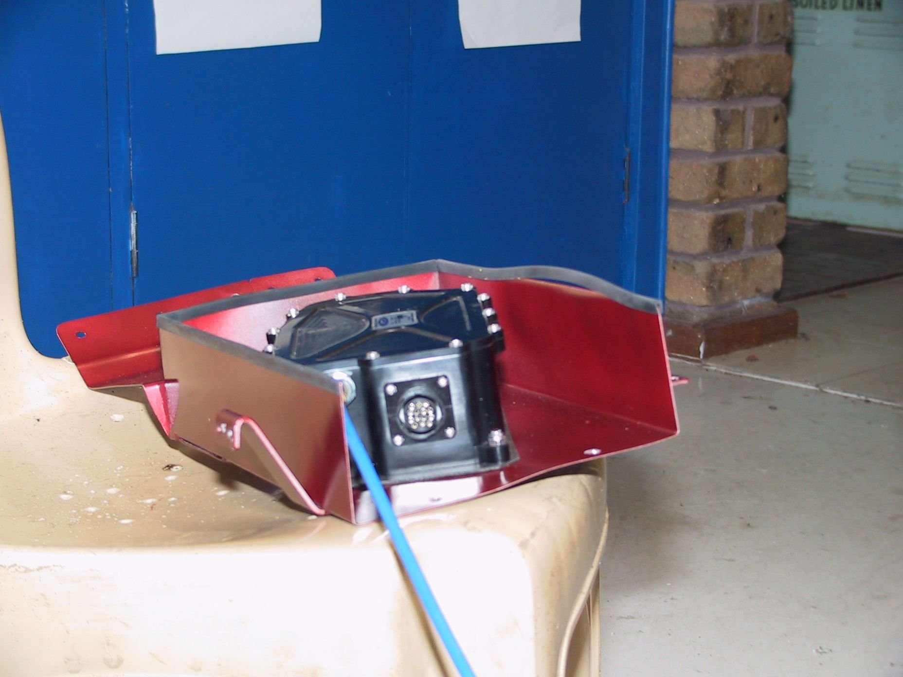
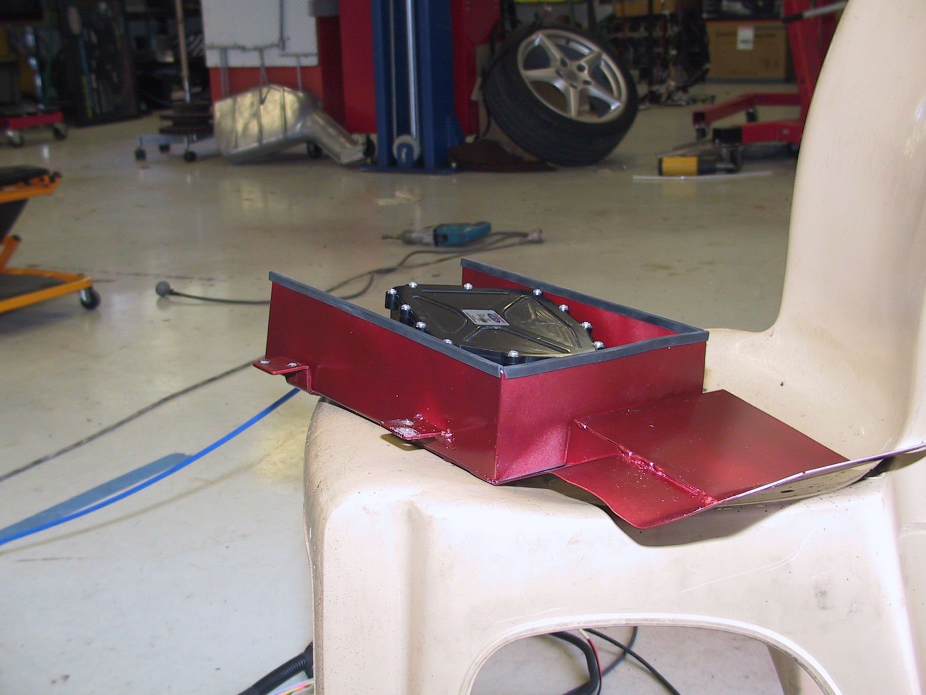
Finally got the Powertrain Control Solutions GSM-5000 gear shifter installed and working.
Biggest hurdle by far was finding a place for the quite bulky 'Cable Motor' unit. The cable is 6' long and using that length up in the 928 was a challenge.
Initially I wanted to put it under the passengers seat but that would leave no foot room for any rear passenger.
Then I went for passenger's foot well against the tunnel but too bulky. Up in the rear mudguard where the radio antenna used to be? Too hard to get the cable to the trans and very long wiring loom path, which is CAN bus for the driver's button panel and the paddle shift option.
Finally it was decided to tuck it up under the LH side front lift point where it is pretty well protected by chassis rails.
It is housed in a stainless steel box with a 'skid sheet' front to deflect any dirt and muck which will come its way, a position for the lift point and sealed against the under floor. it has a yet to be fitted rear door to protect the wiring loom. The wiring loom goes up into the cabin under the ECU.
The programming was very simple and its operation is pleasingly fast. The original Porsche external cable mount was perfect but the Porsche selector lever had to be shortened by 20mm to match the cable's range of travel. A simple extension that also converted the PCS 3/16" UNF cable thread to M5 for the Porsche ball cup, made up the inner cable length. Most of the cable gets covered by the exhaust heat shield.
Other niceties are that it now requires the brake pedal to be pressed to move out of park. It also takes over the park/neutral safety switch as well as reverse light and brake pedal input.
It is one touch to any gear selection, or +/- to go up or down through the gears. So one touch to go from park to second.
Now to fit the paddle shifter to my Momo steering wheel. It is CAN bus to a wireless module that communicates with the paddles.
The video is impressive. I have been wondering if you have progressed much since I saw the car. I will return the alternator one day. Let me know if you want it any earlier.
The video is impressive. I have been wondering if you have progressed much since I saw the car. I will return the alternator one day. Let me know if you want it any earlier.
Greg
Mostly wiring for the Link Thunder ECU. Then before we put the motor in permanently, we wanted to know where the main electrical components were to be physically located, for wire loom paths.
That took us to fitting the gear selector unit.
Now I just want to sort out the ABS to ECU wheel speed sensor wiring [needed for traction control], so we don't have to mess with the ECU wiring once it's all in place.
I've learnt that it is much easier to pull something apart and put it back as it was originally designed! but where is the fun in that?
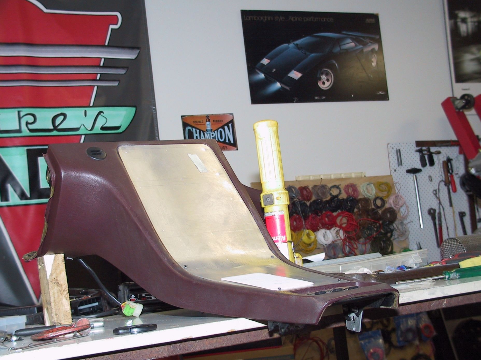
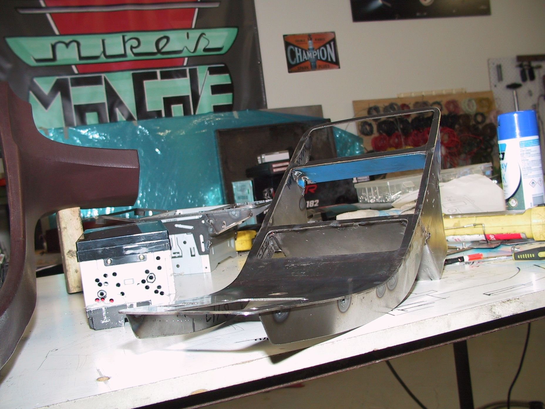
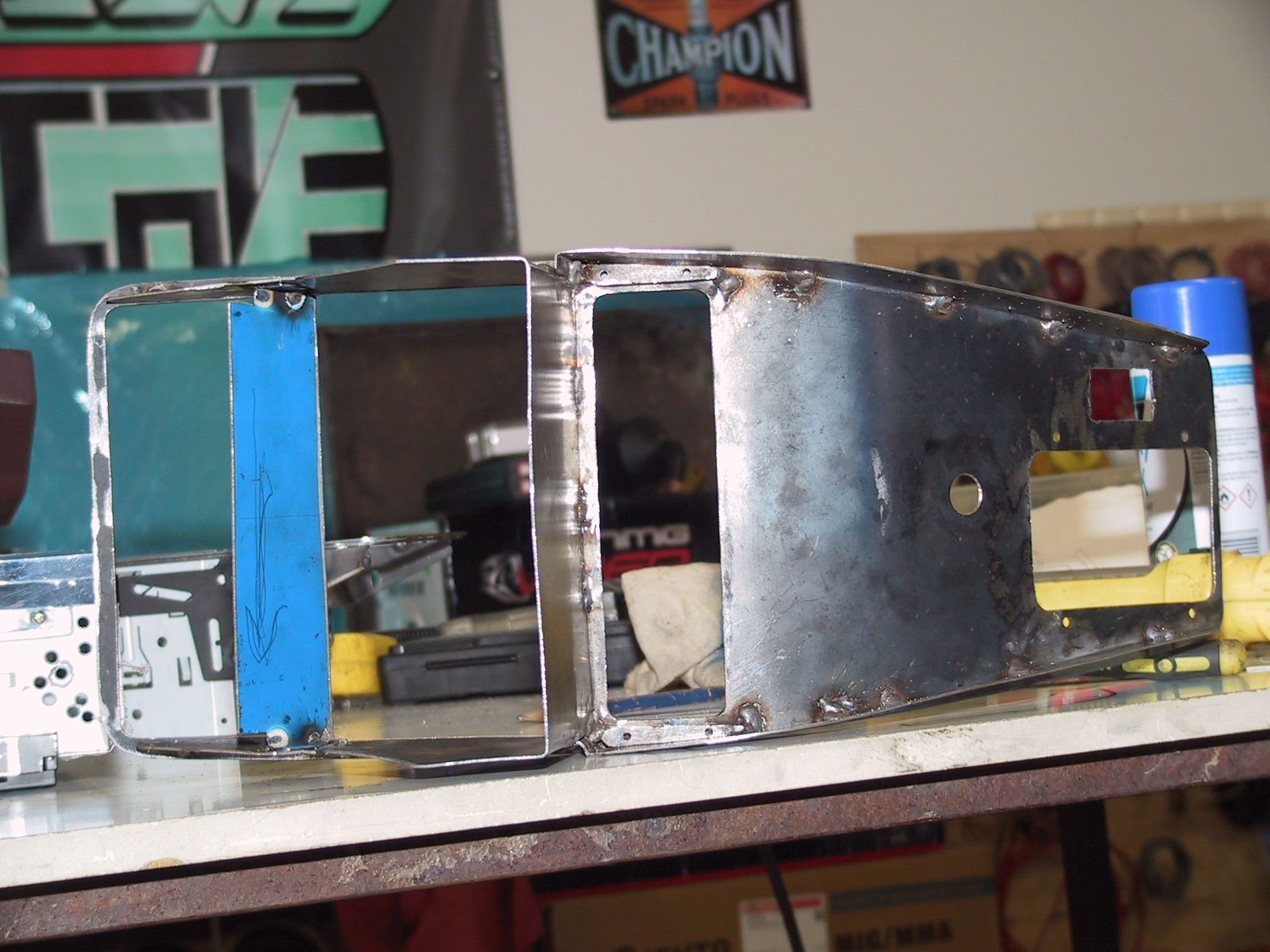
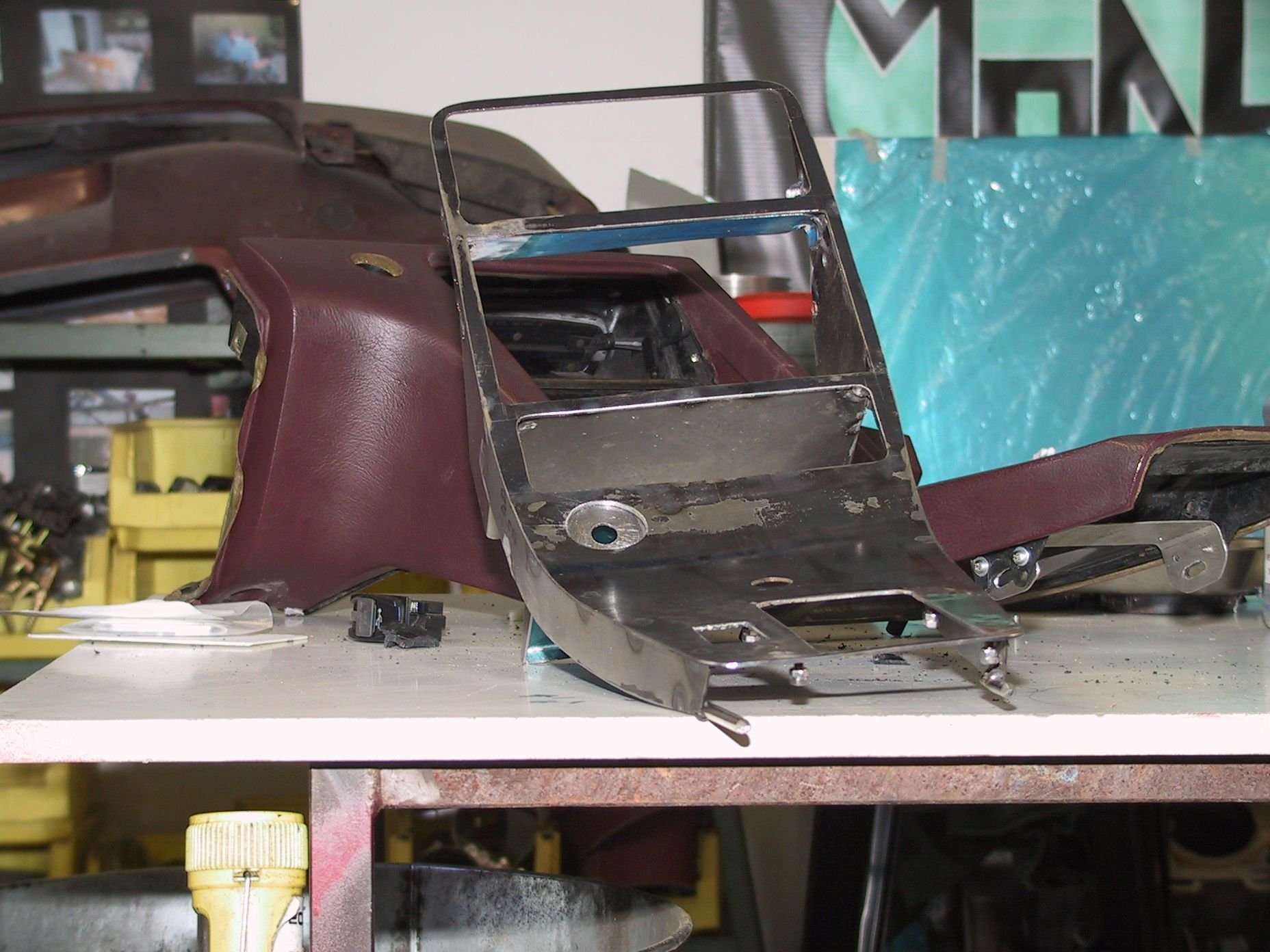
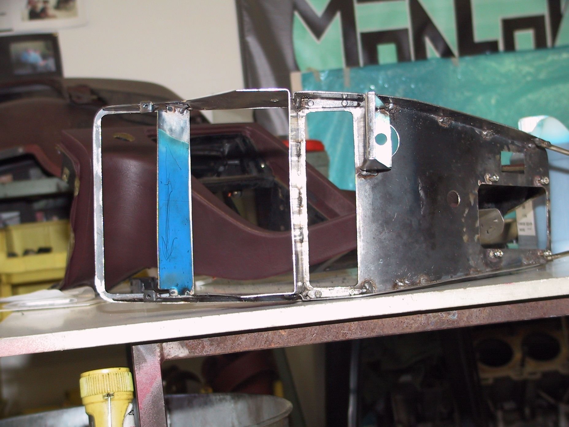
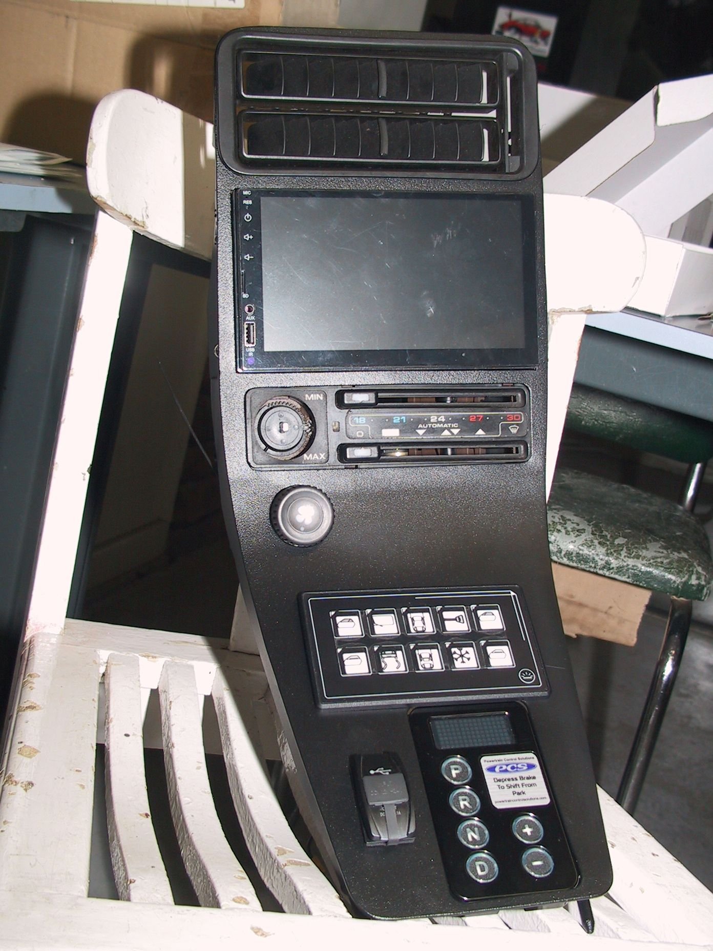
After a few failed attempts, I've settled on this setup for my centre console mod.
Still have to cover over the old HVAC ****, probably with a Porsche logo or something similar, as the blower fan is now controlled by a PWM unit just below its original spot. first failure! raw, no mounts raw back side raw, complete back side complete ready for the old fan **** to be covered
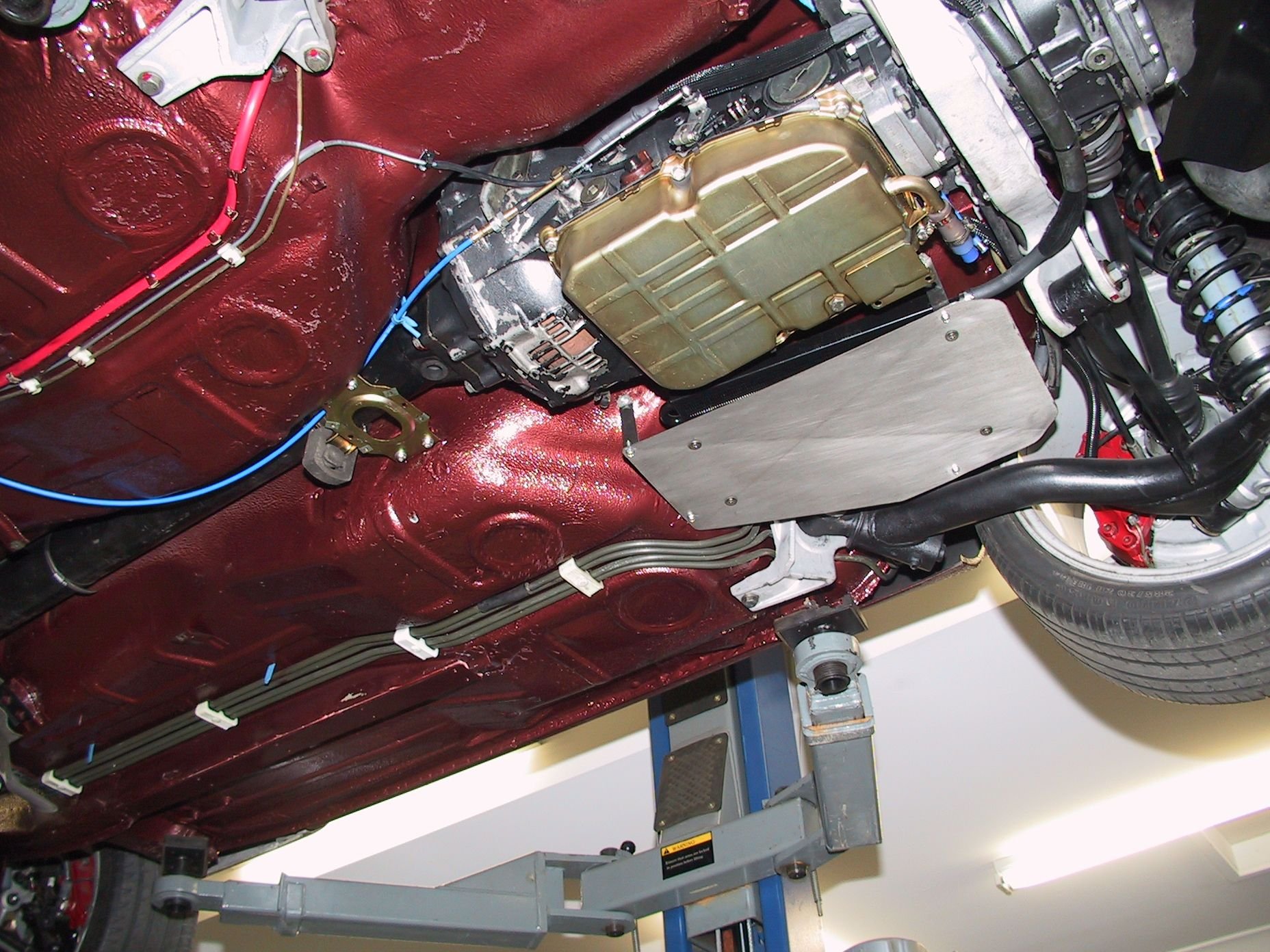
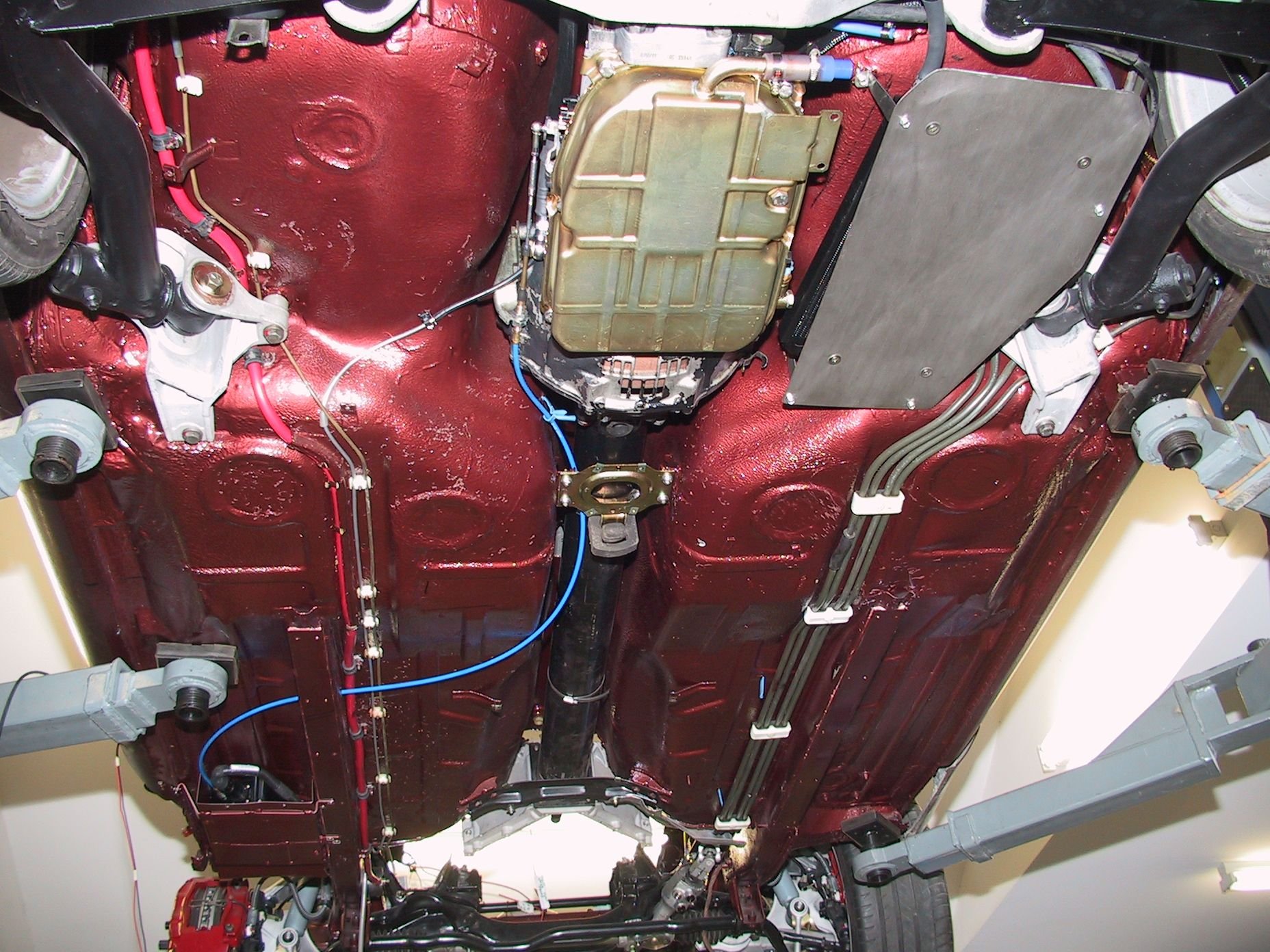
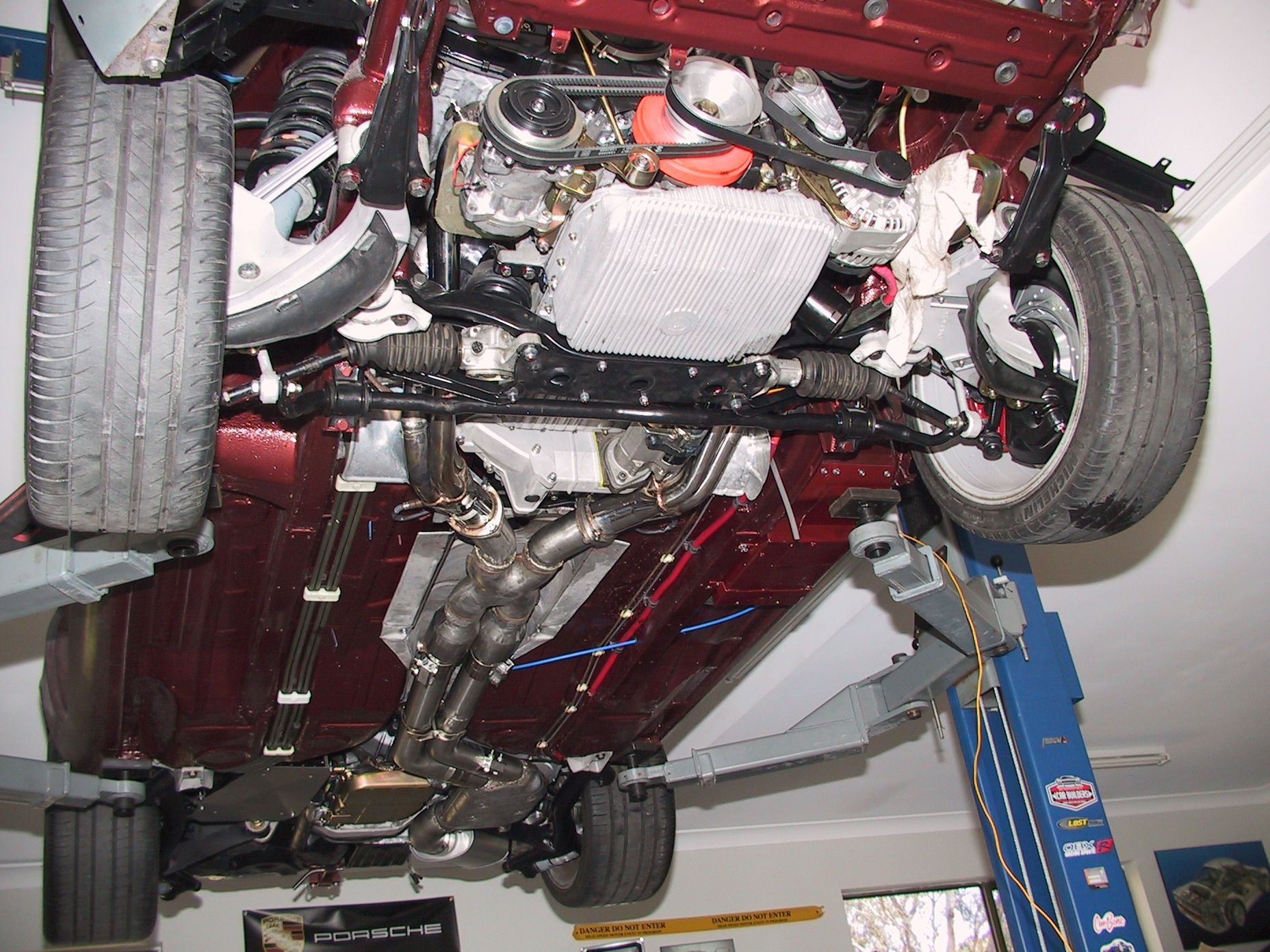
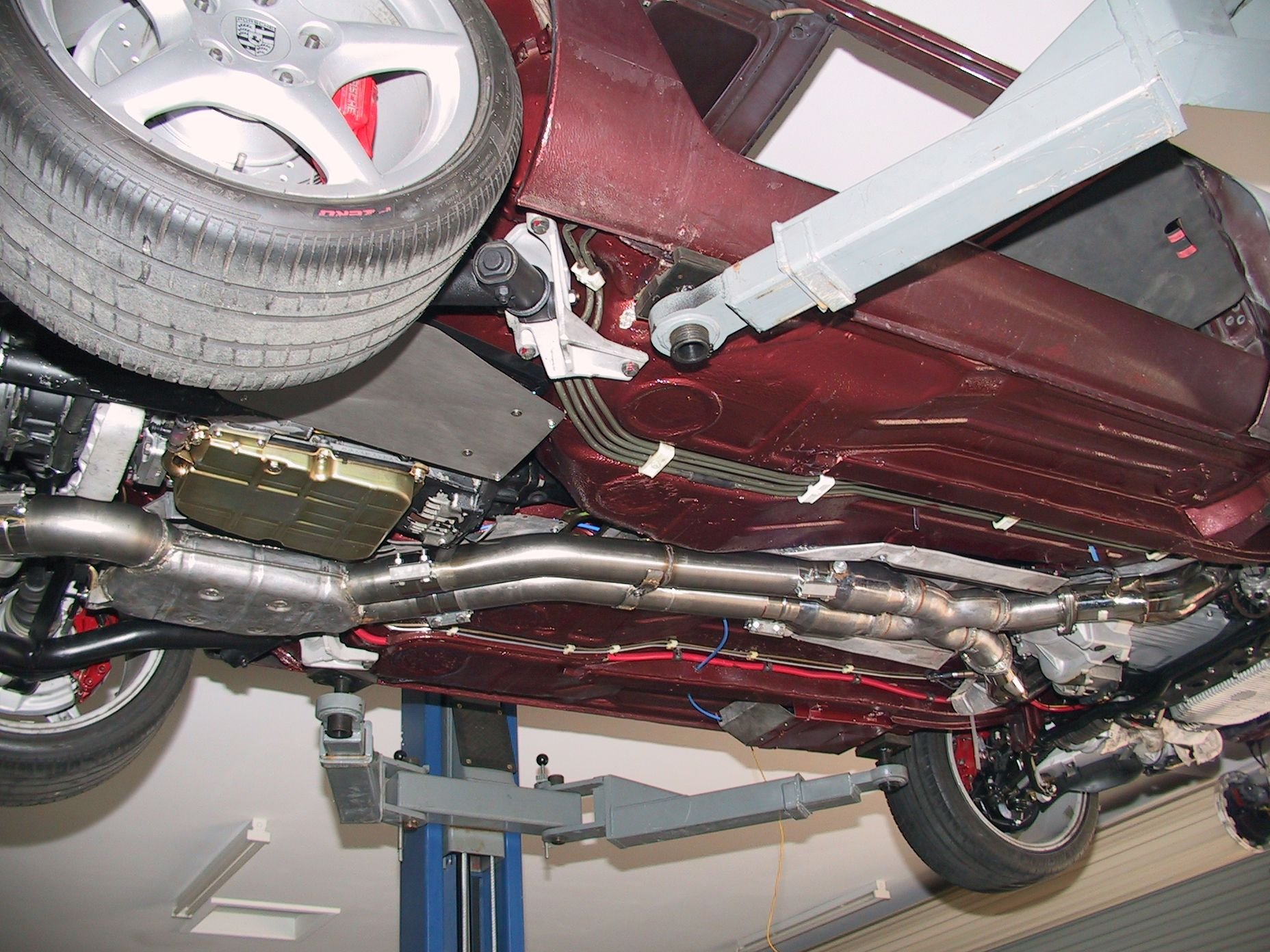
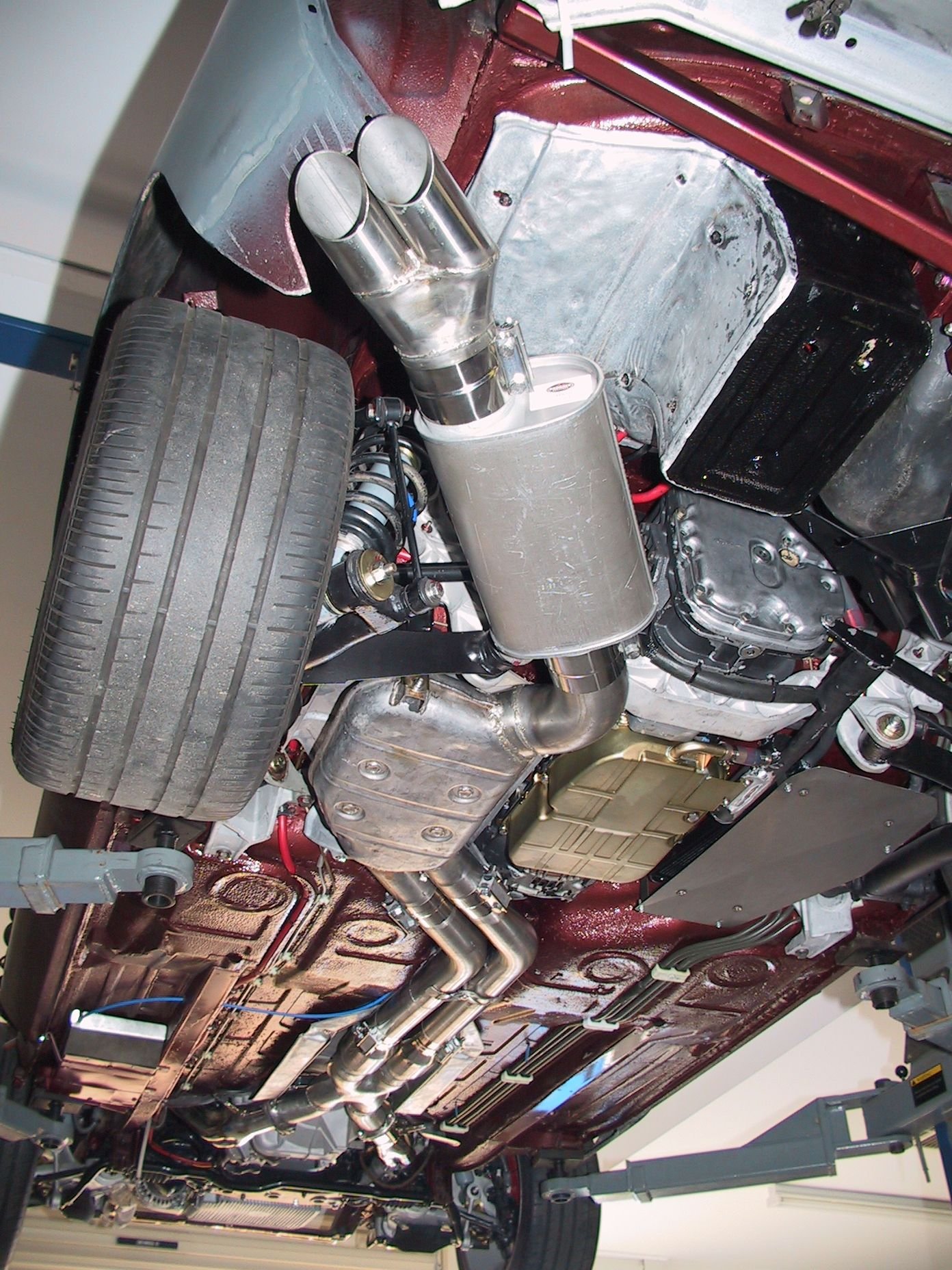
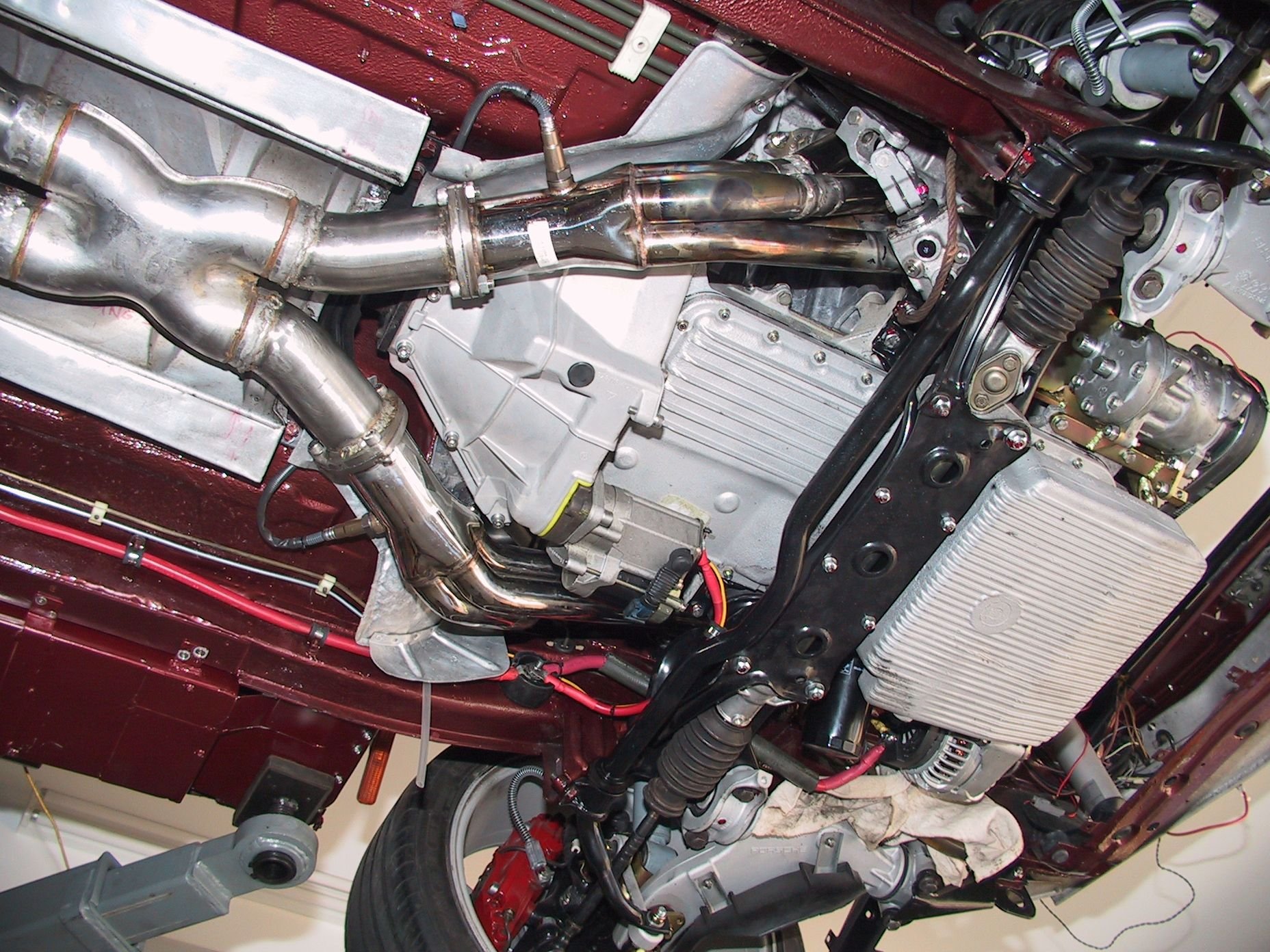
With the exhaust system and steering both in and eventually playing nicely together, the mini torque starter in, just, and able to crank the motor, there is not a lot left to do underneath.
I am considering 2 under trays, from the front chassis member back to the steering cross member and from just behind the steering cross member back to the rear passenger's foot well.
I hope that would smooth off the underneath and keep the muck out.
Meanwhile, still lots of bits to fit to the engine. More bits bolted on went 4" to get under the rear cross member easier than 2 x 3" 2 x wideband O2 sensors mini torque starter
I wish you would get this thing finished off and running- the suspense/sense of anticipation is killing me!
This has to be one of the top 10 all time 928 special project builds in terms of lateral thinking, innovation and application
Well thanks Fred but I'm very careful not to set schedules for it or stages, then I may feel pushed or the urge to rush and there is no rush.
This will be my last 'serious' project and it's complex in some parts [my fault I know] and expensive in most. My wife is incredibly understanding but I must work to a budget.
I'm past most of the big spends, except painting the exterior, 20K maybe? and the CAN bus electrical system still evades me. I did buy the infinitybox system [they should have kept the name isis!] but after countless lies and 2.5 years to deliver what was promised in 6 weeks ish, only to discover it wasn't even finished, I sent it all back. I got a refund and a penalty payment but it was stressful.
We are approaching firing it up. That will require some temporary wiring to liven up the various sub systems like EMS, fuel pumps, steering, gear shift controller for example but doable.
I've got my Radium FPR-D, thanks for the tip and what a beautiful piece of craftsmanship. Complete with a bunch of fitting to match a variety of couplings and some internal spares. So I now have all of the necessary fuel system bit although I think my 547 cc/min injectors may be too generous?
Yesterday, we almost finished the external oil cooler, located under the LHS headlamp to catch air coming in from the brake duct vent. This is version 3 but I'm confident it will get the nod.

 09-26-2020, 04:42 AM