When you click on links to various merchants on this site and make a purchase, this can result in this site earning a commission. Affiliate programs and affiliations include, but are not limited to, the eBay Partner Network.
The AC circuit also goes through the rear defog switch; if it's in de-ice mode (as opposed to de-fog) the buck stops there. Don't know where exactly it is in the order of things but it's my understanding it's before current is presented to the evaporator freeze switch.
Porsche says you don't deserve Air Conditioning if you are melting ice off the rear window....now go to your room.
No - this is not how it works. Rear defrost/defog is not related to AC in any way.
ramcram you are doing some very interesting things with your build!
Nice job on the exhaust system, I'll bet it will be on the loud side!
I truly hope it is not loud.
I'm about to do some not very scientific noise tests. I will put my sound meter at one end of the modified muffler and a horn at the other end then measure the sound level.
Then repeat it with the 4" in/out commercial muffler I have for the rear.
Then again with the horn and the meter the same distance apart with nothing between them.
I guess I can always put 2 'hot dog' resonators after the 4" muffler if it is too loud?
ramcram you are doing some very interesting things with your build!
Alan
Thanks Alan, I think? or is that like telling a politician that he's making a 'brave' decision?
I confess to often wanting to 'go my own way' as it were but I do base my plans on a lot of reading and learning from other's adventurers.
I finished my apprenticeship as a motor mechanic in the early 1970s and worked on things like Caterpillar bulldozers, right down to chainsaws and dirt wakkas, so I have seen inside a few machines.
My plan with this project is still to end up with a car that still looks like a stock 928S but has 2020 [or 2030 when I get there] technology under the skin.
To that end, I have just ordered a Powertrain Control Solutions GSM5000 transmission control system. This will let me select/shift gears by the touch of a button, or by wireless paddle shifter but I do't think I need that option.
Mike
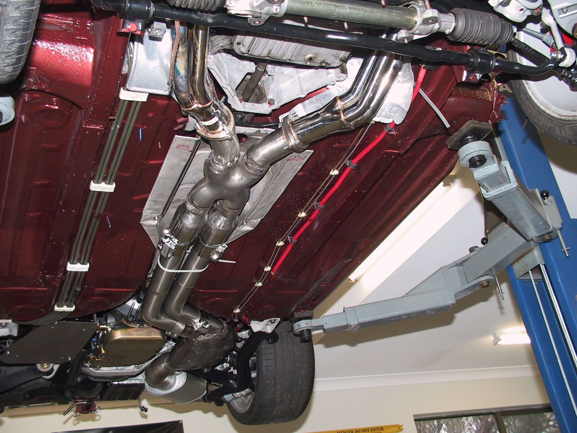
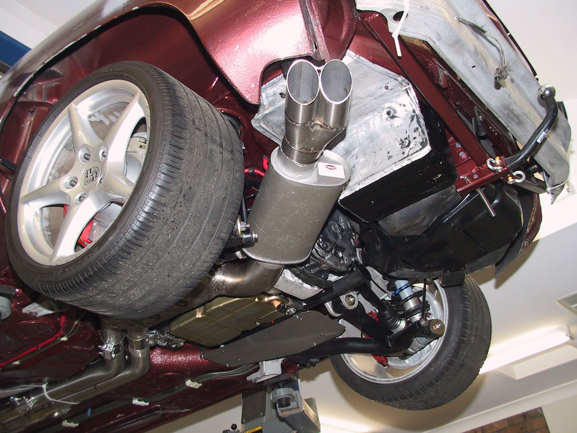
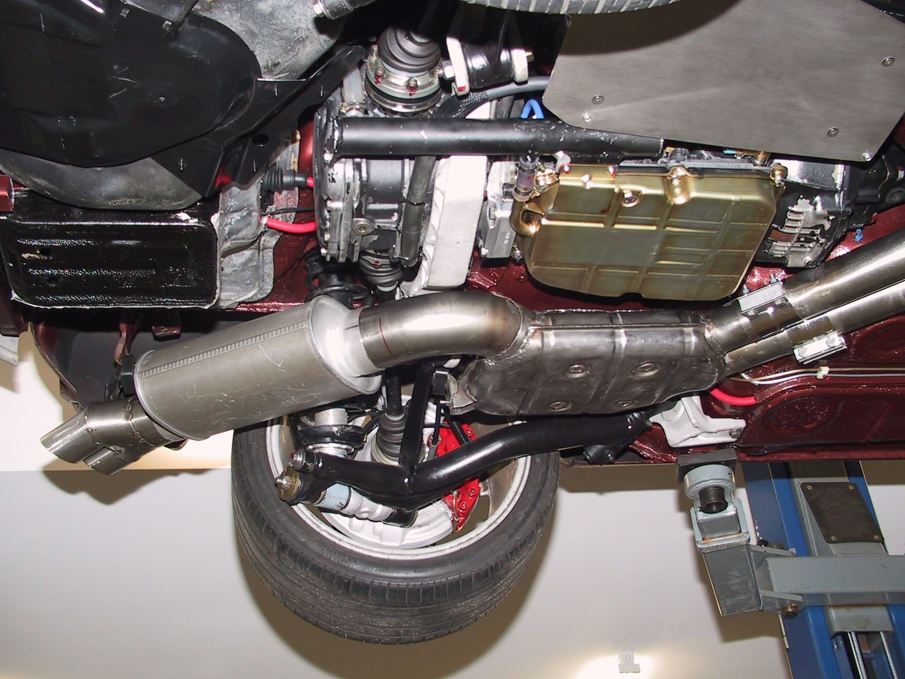
Finally got the new exhaust system tacked up ready for the welder to finish off.
I'm pleased with the out come of the centre muffler in particular, worth all the stuffing around. It clears every thing, just and the tail pipes will look pretty 'normal' from the outside when it's on its wheels.
Now the headers need to be finished off so they clear the RHD steering column.
Ah, well!
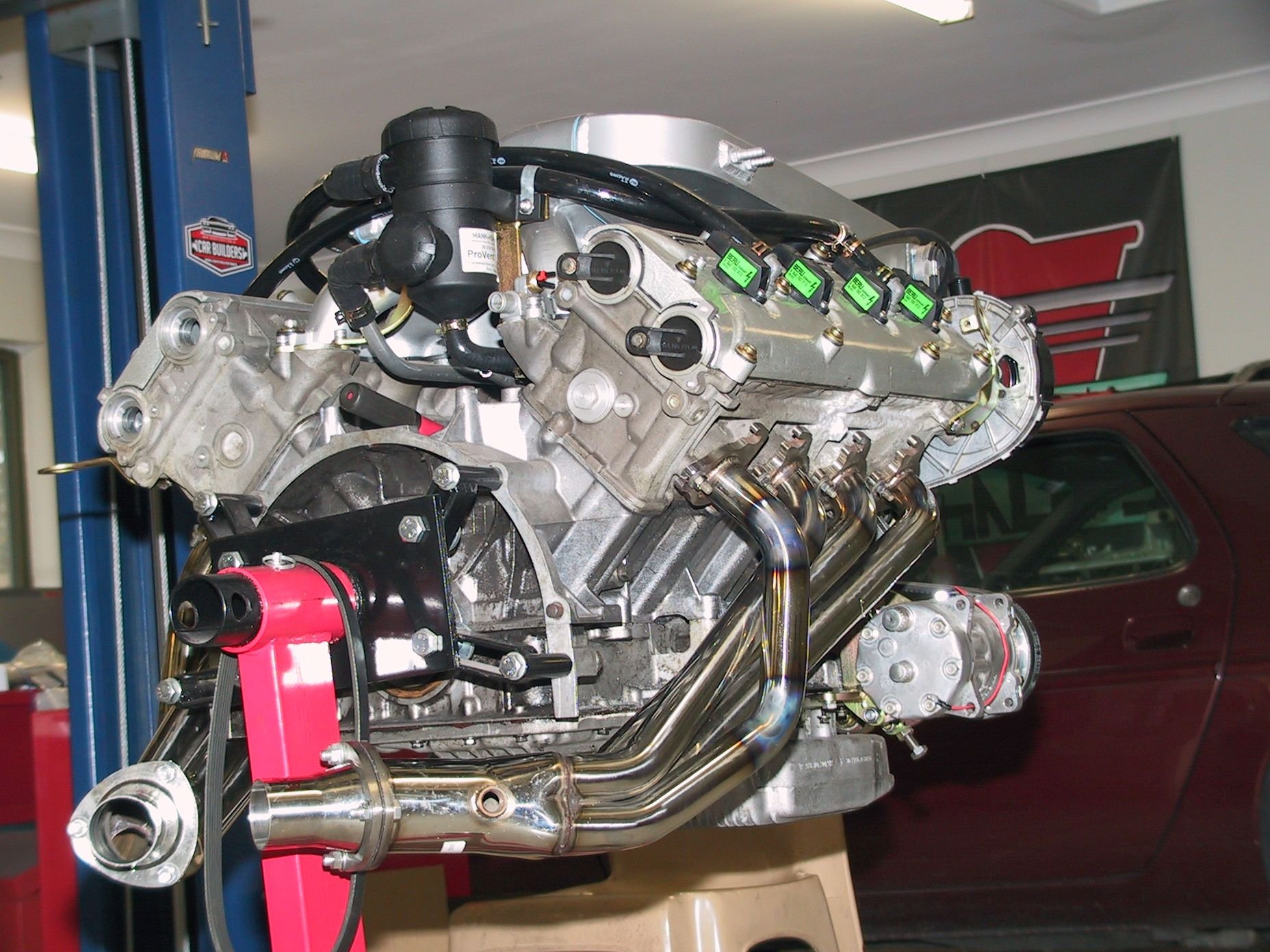
Now the pipes can come off to be fully welded, the dummy motor can come out, which has the 'real' heads on it, they can then be permanently fitted to the 'real' motor and it can be fitted in the chassis.
Before the motor goes in, I want to wire it up for the Link Thunder ECU, on the engine stand, just for comfort and while this is happening, the car will go to the body shop for some minor work, like filling he door key holes and the side strip holes.
Then, motor in, connect up a few things and time for some noise, sorry, music.
So, maybe, sometime later this year? There is still a heap of things to do, and why rush while it's still fun?
I'm trying to find out what current supply I will need for my 8 Beru coil-on-plug units, from a Porsche Cayenne.
I found this data from in an article on the development of the Cayenne coils.
Beru Coil-On-Plug Data
Primary current [A] 9 15
Current-rise time [ms] 1.75 2.4
Secondary voltage [kV] 1 MOhm // 25 pF 26 31
Energy data (secondary load,
1000 V Zener to ISO 6518-2)
Spark duration [ms] 1.7 1.85
Spark current [mA] 60 80
Spark energy [mJ] 45 65
I don't know why they have 2 columns of data for each value?
I just want to know what current is required to feed the 8 coils in service?
It seems a huge current for sure. Maybe buy one and see what the d.c resistance is and do some tests.
John, I have the 8 of them but I don't know how to achieve what your suggesting?
Here's the info I've collected.
5V falling edge, min 18mA
pin-1=ecu ground
pin-2=engine ground
pin-3=12V constant
pin-4=5V trigger
John, I have the 8 of them but I don't know how to achieve what your suggesting?
Here's the info I've collected.
5V falling edge, min 18mA
pin-1=ecu ground
pin-2=engine ground
pin-3=12V constant
pin-4=5V trigger
Mike
Just measure between the (two?) terminals with a meter on ohms for a start.

 06-04-2020, 05:27 PM