When you click on links to various merchants on this site and make a purchase, this can result in this site earning a commission. Affiliate programs and affiliations include, but are not limited to, the eBay Partner Network.
Yes, 12v from the relay in the aircon control head goes via the Thermoswitch (Evaporator switch) to K21 CE and to the suppressor relay X! which is diode to ground. 12v then goes out of the CE panel on M12 to the low pressure switch and finally to the compressor clutch.
OK John I've got it, thanks.
What does the 'suppressor' do? me thinks it probably stops radio interference when the compressor cuts in and out?
We [my buddy and I] are rewiring the whole car but not as stock. I'm going to use Power Distribution modules front and back to limit the amount of 'load carrying' cables in the system.
I am however, using the stock wires where ever I can so I don't have to write a whole new wiring diagram! Plus it's hard to find all the different colours/weight combinations used in the car.
A lot of my wiring will only be carrying 'signal current' to the central controller, so they will be on light duty as it were.
Also, all lights are LED which drops the load a lot.
The 'suppressor' is just a diode. It is reverse biased when +12v is applied to it. But the compressor clutch solenoid is a highly inductive low impedance load. Switching it can cause large negative spikes (below ground potential of battery negative.) The diode is there to suppress that possible negative spike.
I've been following your project with great interest, a fantastic job :-)
Originally Posted by ramcram
OK John I've got it, thanks.
What does the 'suppressor' do? me thinks it probably stops radio interference when the compressor cuts in and out?
We [my buddy and I] are rewiring the whole car but not as stock. I'm going to use Power Distribution modules front and back to limit the amount of 'load carrying' cables in the system.
I am however, using the stock wires where ever I can so I don't have to write a whole new wiring diagram! Plus it's hard to find all the different colours/weight combinations used in the car.
A lot of my wiring will only be carrying 'signal current' to the central controller, so they will be on light duty as it were.
Also, all lights are LED which drops the load a lot.
The AC circuit also goes through the rear defog switch; if it's in de-ice mode (as opposed to de-fog) the buck stops there. Don't know where exactly it is in the order of things but it's my understanding it's before current is presented to the evaporator freeze switch.
Porsche says you don't deserve Air Conditioning if you are melting ice off the rear window....now go to your room.
Yes, the defrost system turns the blower on max. I'm not letting it do that because I'm using a PWM fan controller instead of the old resistor bank. This seriously reduces the current draw and inrush, which I'd loose if I let it go full blast.
Here's my schematic if anyone is interested.
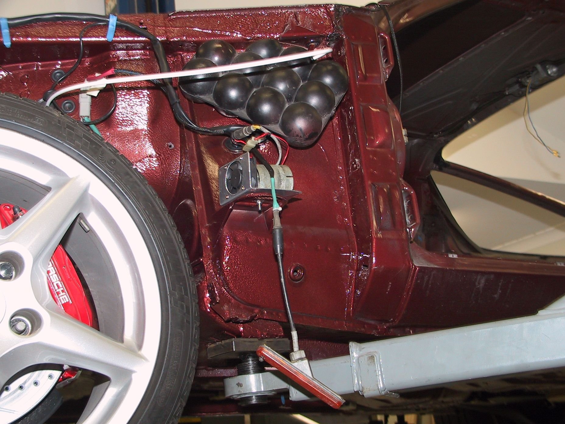
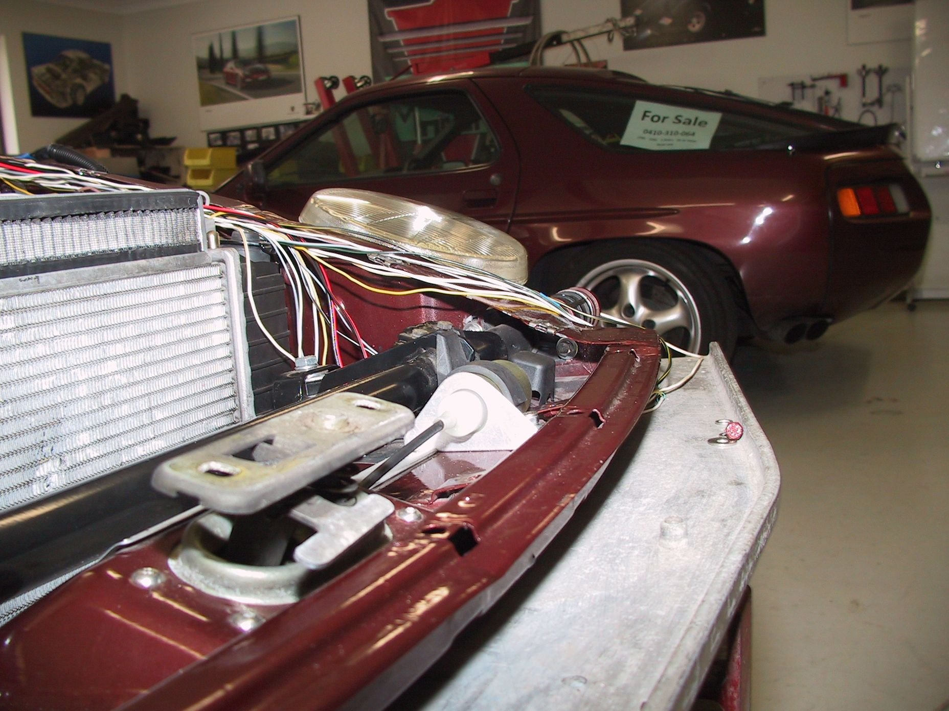
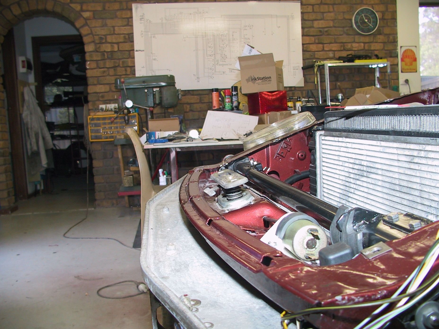
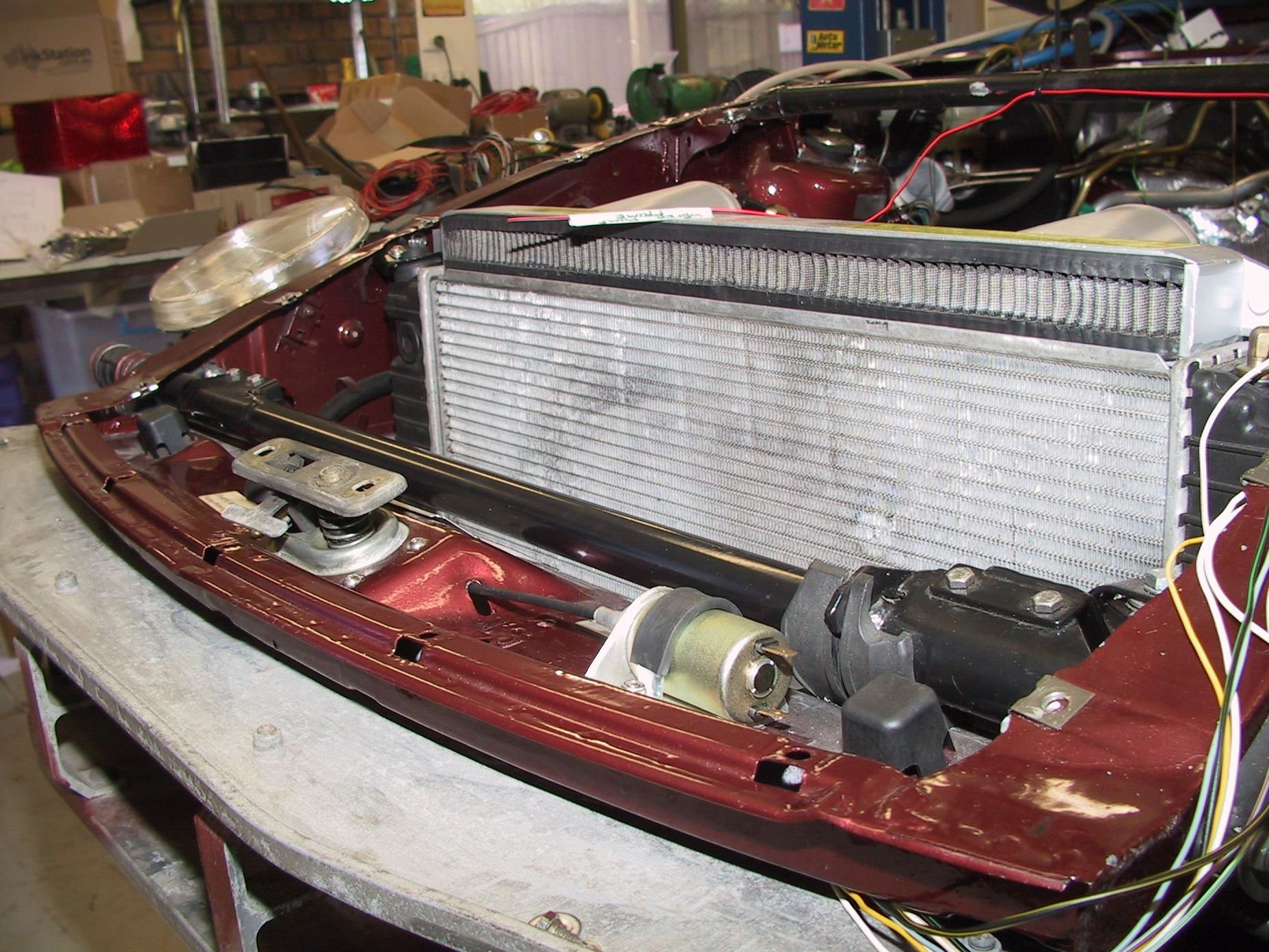
On the wiring!! my biggest system mod, some progress has been made. The external temp sensor got moved from the front of the LH guard [fender] to the rear, sitting on the old cruise mount that is no longer required. Cruise now handled by the engine management module and ETBs. Stuck in here I thought it might need some air flow, so it has a 60mm computer case fan, same idea as the stock cabin sensor.
My alternator has 2 internal fans and no way to use the duct tube to breath on the temp sensor, plus I have an engine oil cooler and fan going under/behind the LH headlamp.
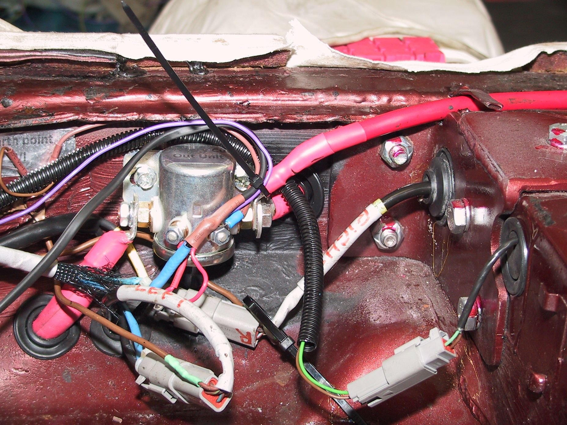
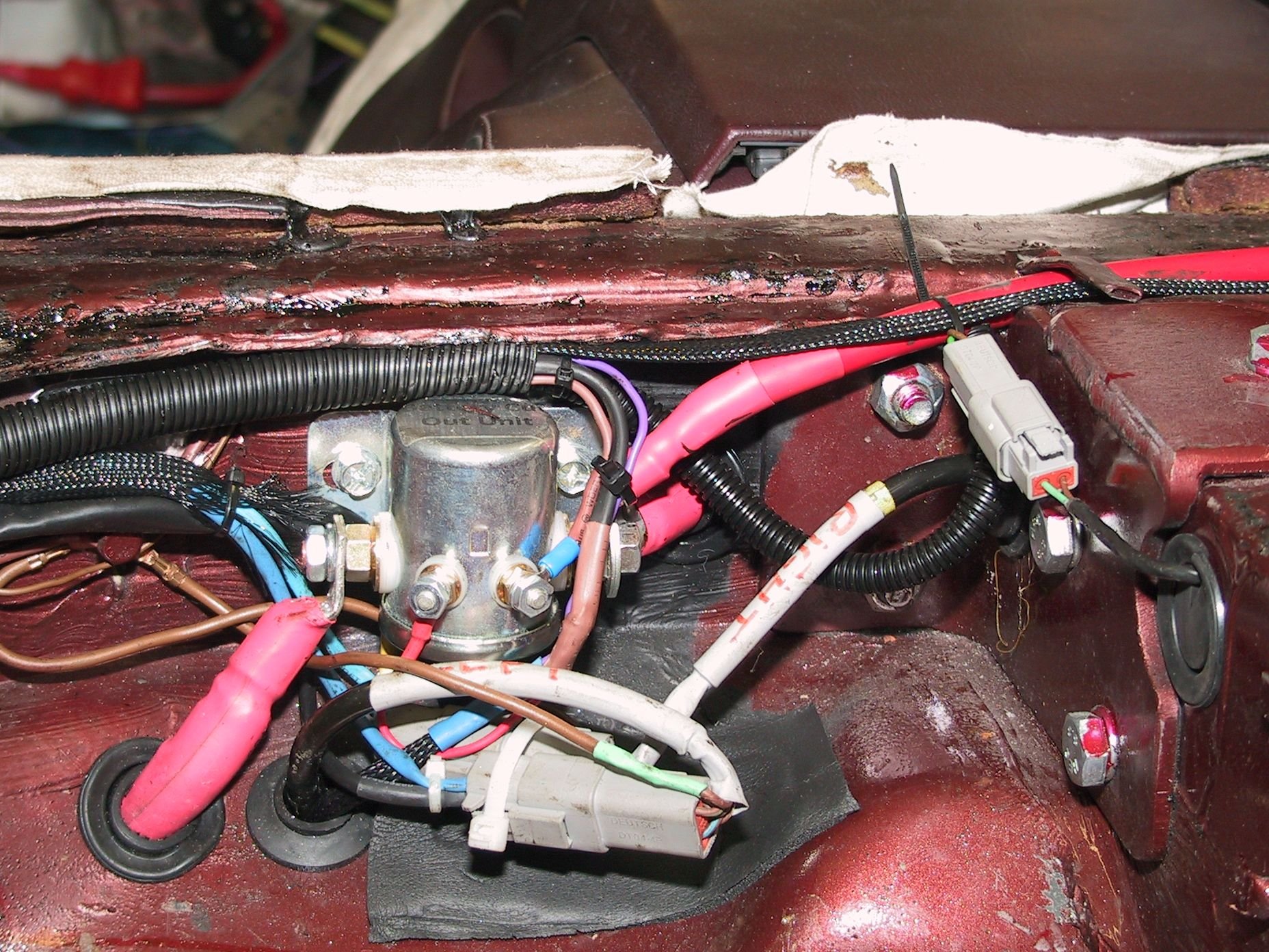
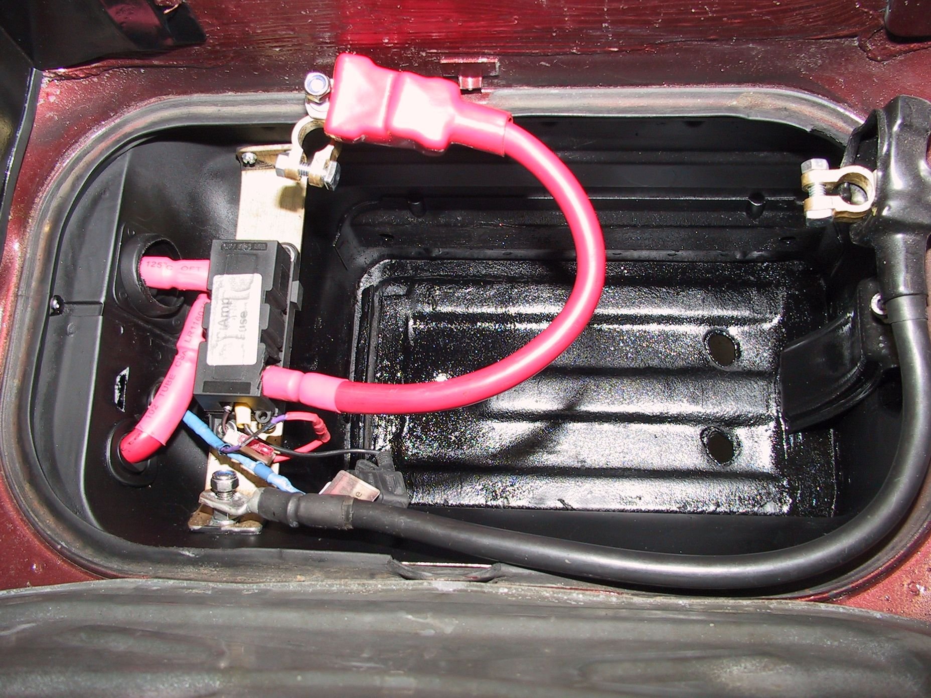
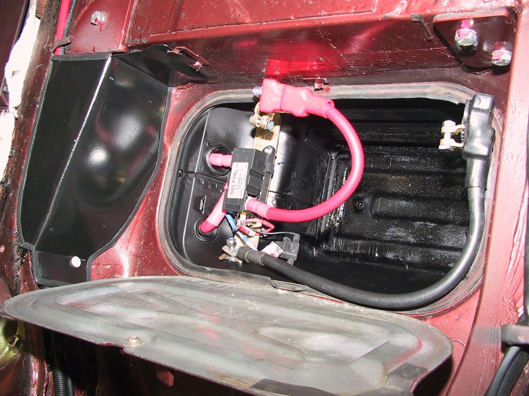
Finally got the battery cables sorted, through a 400 Amp Megafuse and a low voltage disconnect solenoid which is button controlled from just inside the hatch in the tool compartment. This will drop out if the battery voltage falls too low, or it can be forced to 'unlatch' by pressing the button.
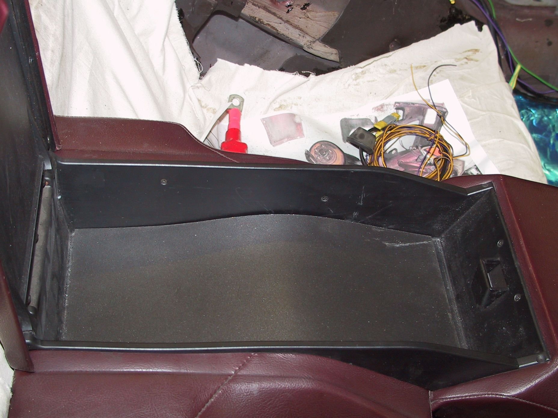
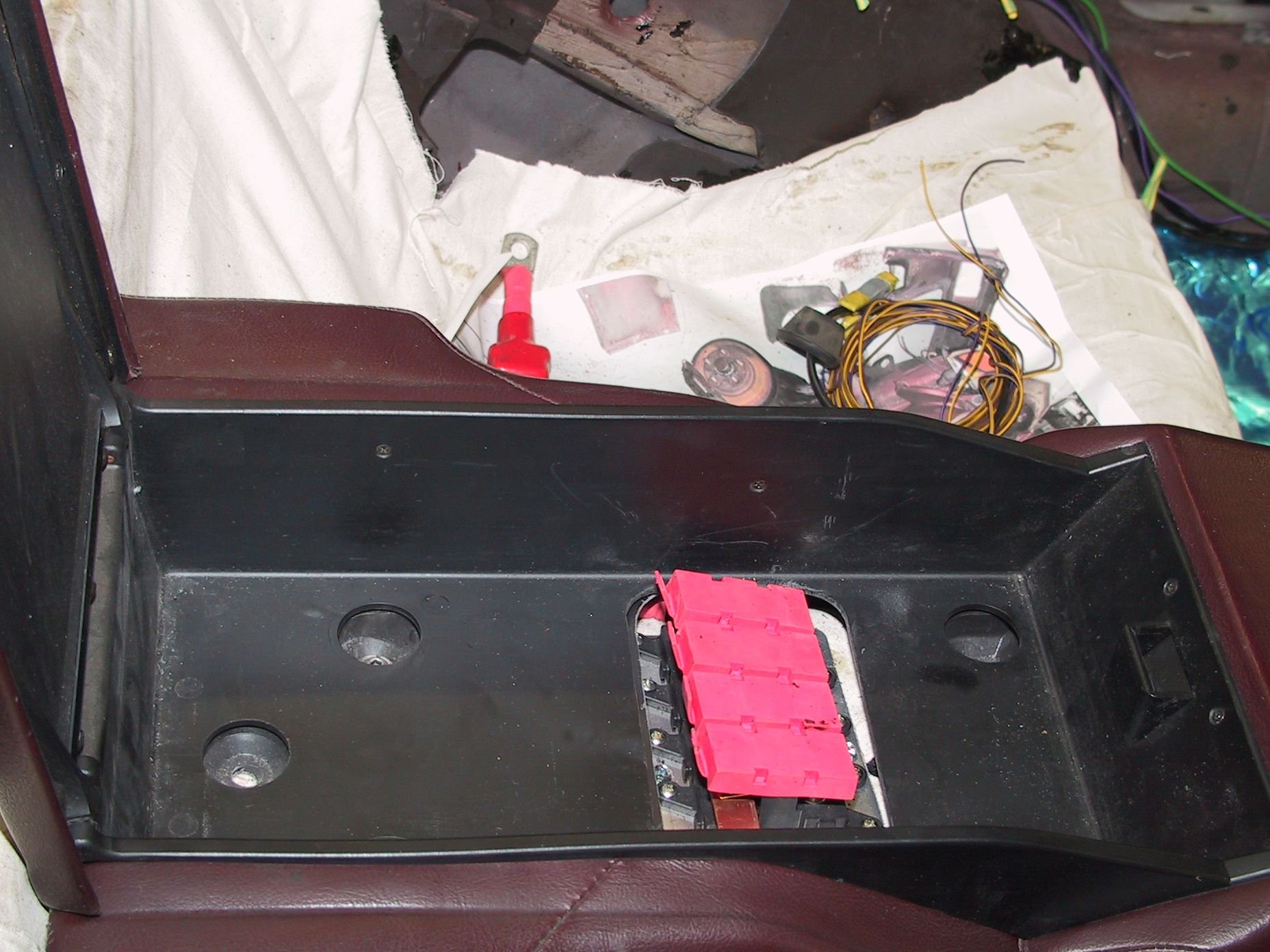
Fitted 4 x 70 Amp Minifuses inside the rear storage box. These will feed 4 6AWG cables to the passenger's footwell [well away from starter pulses] and power most of the front electrics.
I want to use the original cable colour and size where I can, for later diagnostics,so a lot of labeling and laying wires in there rough paths at the moment.
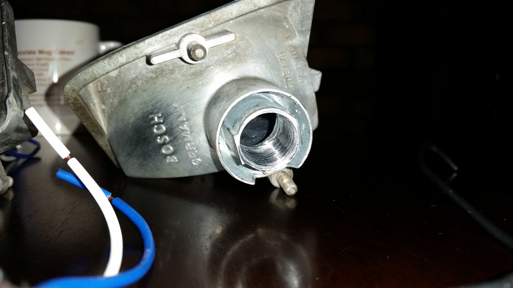
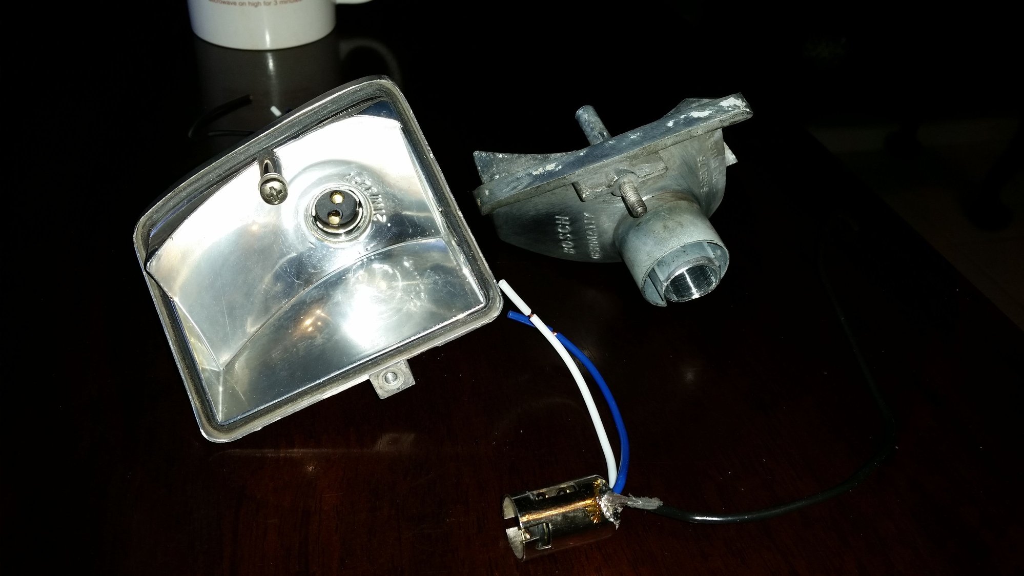
Got the Day Running Lights sorted. Used 'switchback' LED bulbs that will power up white on engine start but drop the white when the amber detects voltage. They automatically switch back to white after a few seconds of no voltage on the amber circuit. Using clear front indicator lenses. Had to drill out the cast bayonet single filament mount and fit a double pole mount.
Lots of tidying up, then a wheel well cover to be made.
Relocated the external temp sensor with its own fan, now that the alternator can't circulate air through it and the oil cooler will crowd out its original home. Will wire it through the PWM controller for the blower fan.
Finally tidied up the battery cutout and the battery box/fuse setup. The brass bar that holds the 400 Amp fuse is both bolted and soldered to the body to ensure a good earth.
The new battery cables, to cope with the new alternator, are way too fat to use the original path.
Ran a separate 'hot' wire for the radio so I don't have to reset the radio every time the battery is disconnected. Tidied wires. New [smaller] ABS plugs New earth strap + battery main fuse New cover for battery latch etc.
Where are you tapping into the intake manifold to get the MAP signal for the Link ECU? Use the bottom hole of the flappy axis?
I have a boss into the top of the '89 manifold in the cross port where the flappy was, angled to give more bonnet [hood] clearance. I have read that it may not be necessary with the Thunder, with built in barometric sensor for NA engine???
I've fitted the IAT sensor into one of the inlet pipes from the air cleaner.
So, school's still out there!
I have a boss into the top of the '89 manifold in the cross port where the flappy was, angled to give more bonnet [hood] clearance. I have read that it may not be necessary with the Thunder, with built in barometric sensor for NA engine???
Well, the ECU needs an analog input for load, whether it be MAF, MAP or TPS, and using MAP with a Link G4(+) ECU and a non-ITB set up is probably the most straightforward way to go to, feeding the internal barometric sensor with the MAP signal.
The barometric sensor needs no MAP input if you decide to use MAF for load, and can be used to ponder fuel delivery in function of altitude. Doesn't the original LH use a barometric sensor for this already?
I have jump terminals by the number plate lights, plus I can open the hatch, plus the release mechanism is accessible from under the front of the car.
I hope I don't get too many dead battery issues [hope is wonderful!] with a low voltage latch which will disengage the battery if the voltage falls.

 12-11-2019, 02:05 AM