Low cost MINI-STARTER
#48
Also, confirmed the starter motor itself if a stronger 1.6KW for the larger high compression 928 motors.
The one thing I will need to do is cut the ring connector for the starter switch from my new harness and change it to the spade connecter for this. That's a bit of a bumper. I wish this had a post style so I didn't have to modify my harness. It will be a while before I install this guy, I need to finish some interior and AC work first. Maybe this spring.
#49
Well, if altering the harness is important, you could simply attach a ring terminal to a spade terminal. Use the shortest bolt possible to attach the two rings and make sure you insulate the connection well.
A short section of vac hose, or the 'self vulcanizing' tape would be my choices.
A short section of vac hose, or the 'self vulcanizing' tape would be my choices.
#50
Well, if altering the harness is important, you could simply attach a ring terminal to a spade terminal. Use the shortest bolt possible to attach the two rings and make sure you insulate the connection well.
A short section of vac hose, or the 'self vulcanizing' tape would be my choices.
A short section of vac hose, or the 'self vulcanizing' tape would be my choices.
#54
My 84 has three wire connections. The large battery cable, the medium sized starter switch cable and a small cable that goes to the coil and resistor circuit.
Thanks,
Dave
Thanks,
Dave
#55
I called the vendor can confirmed a couple details about the starter. Yes the is clocked properly already so I will not need to make any adjustments. The aluminum adapter bracket and drive gear are specific to this starter and are designed to match up to the ring gear completely.
Here's the same IMI-101-928 starter in situ on our '90 GT, with the starter inboard and tucked under the engine oil pan. This is necessary given the bundle of snakes (Devek L2 headers) outboard of the starter. This puts the spade terminal on top and the big wires on the outboard side.
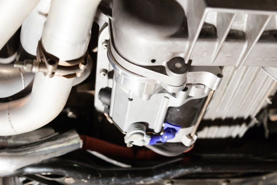
If this is the orientation that you prefer then you need to reverse the mounting plate. Easy to do, two Allen-head screws.
Here is the issue: Note that the mounting plate is asymmetric: The side with the "IMI-101-928" stamping is wider than the other side. If you want the motor oriented inboard (as above) the "IMI" designation wants to be inboard, TOWARDS the motor, thusly:
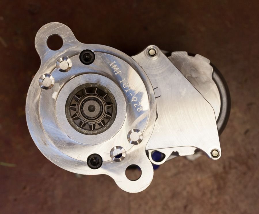
Here is the starter clocked as above, mounted on an engine on a stand (no bellhousing, no oil pan). The pinion-gear mesh is perfect.
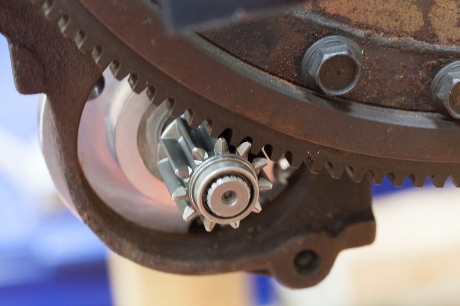
Now here is the same orientation except with the "IMI" designation AWAY from the motor (as yours was shipped):. This is NOT going to work:
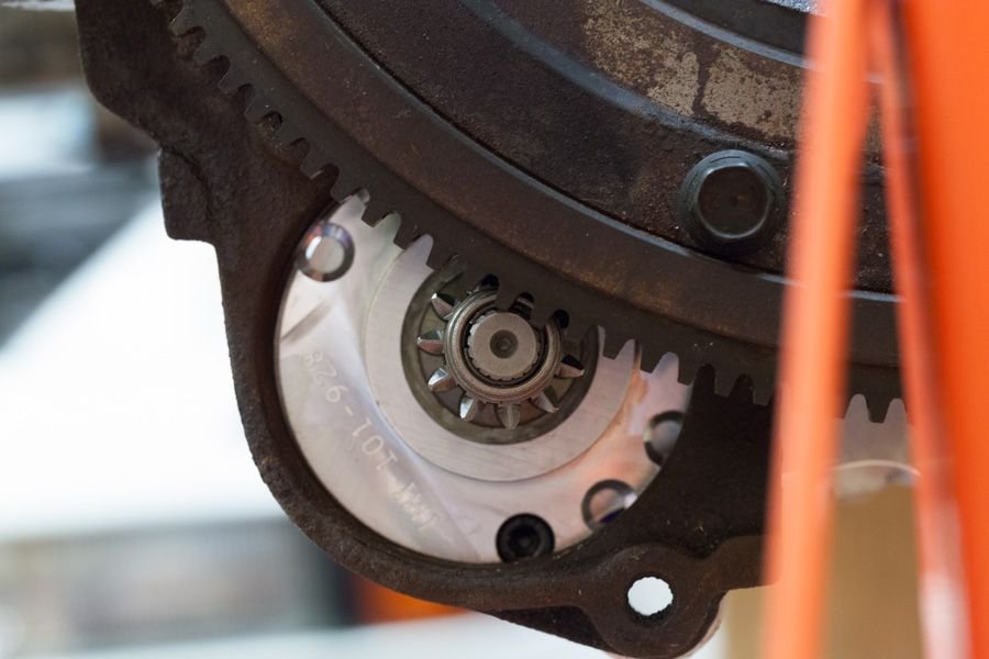
Now here is the same clocking except with the starter turned over and oriented with the motor outboard of the oil pan, fits perfectly:
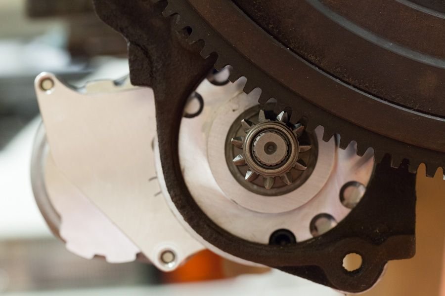
Viola, pinion gear engages perfectly but the motor is outboard of the oil pan, and AWAY from the "IMI" designation. That will not work with headers, but might work with stock exhaust. .
So rule of thumb: The "IMI" part number (and the wider part of the mounting plate) always goes inboard of the starter pinion, then clock the motor wherever you want it. Putting in inboard (as in the first pic) gets the motor farthest from the exhaust heat and is what I would personally call "properly clocked".
#57
I have an email into IMI, but I am concerned about wire connections to this beautiful item. My 84 does indeed have three wires to connect to the starter. Is there a third terminal on this starter? Maybe under the blue cover? Can I wire it in some other way to make it work for my car? My third wire goes to my coil and resistor circuit, and somewhere Greg Brown mentioned attaching this to the starter switch terminal with a diode. Any help appreciated before I order.
Thanks,
Dave
Thanks,
Dave
Last edited by j.kenzie@sbcglobal.net; 03-05-2018 at 10:24 AM.
#58
I have an email into IMI, but I am concerned about wire connections to this beautiful item. My 84 does indeed have three wires to connect to the starter. Is there a third terminal on this starter? Maybe under the blue cover? Can I wire it in some other way to make it work for my car? My third wire goes to my coil and resistor circuit, and somewhere Greg Brown mentioned attaching this to the starter switch terminal with a diode. Any help appreciated before I order.
Thanks,
Dave
Thanks,
Dave
The wiring diagram for the '84 does indeed show a third connection on the starter for the US/Japan cars, so I guess you are not crazy

The extra connection is a second switch contact which connects the 12v battery lead directly to the ignition coils, bypassing the two resistors. Prior to electronic ignition, coils would overheat if fed with a constant 12 volts so a ballast resistor was used to limit the current. However the battery voltage drops when starting, so there is a bypass to provide full voltage to the coils when cranking. This is the third terminal.
And yes, a diode from the starter-switch contact will accomplish the same thing and work fine. (Never bet against GB, by the way). I don't know what the coil current would be, but I would think a 10 or 20-amp rectifier diode would do nicely. The "arrow" (direction of current flow) points towards the coil.
But are you sure that your starter is the problem? I would check over the connections and terminals carefully first. The IMI starters work fine and are really nicely made, but it is hard to say that they are "better" than the stock starter for stock applications. Mostly they get used to provide clearance for a pan spacer or some other necessity.
There is one more wrinkle with the IMI, the orientation of the 12v stud which I will post shortly.
Last edited by jcorenman; 03-05-2018 at 03:02 PM. Reason: typo
#59
Thanks, Jim. I'm still holding out hope for my Bosch starter, since it has been working great since I cleaned the terminals (which seemed fien) and fully charged my battery. The IMI is a fall back plan for me if my starter begins to fail again, after repetitive testing.
Thanks again,
Dave
Thanks again,
Dave
#60
Well, I caved in and ordered the IMI-101-928 mini starter. I will wire with a 15 amp diode to the coil resistor circuit from the starter switch terminal. I was stranded recently, and just don't have confidence in my Bosch starter. My car is an automatic, so push starting is not an option.
Thanks for all the great information and support. I don't know what I would do without the people on this forum,
Dave
Thanks for all the great information and support. I don't know what I would do without the people on this forum,
Dave


