When you click on links to various merchants on this site and make a purchase, this can result in this site earning a commission. Affiliate programs and affiliations include, but are not limited to, the eBay Partner Network.
Mike it looks like you could use a heat shield for the new starter,
and also get a Greg Brown flex line for the slave cylinder.
This fits from the slave to the sway bar mount and its a lifetime line
For some extra oomph fit an X pipe
Here ya go with heat shield. On a side note, drove my '86.5 after months of Winter storage, and forgot what an awesome sound the X-pipe & RMB they have.
Hi Alex,
The starter has been fine. It does sound a little different, but I've forgotten exactly how the old one sounded. I got the diode on Amazon. The starter comes with a pigtail, so you won't need the female spade in my diagram. I also used the starter power terminal right angle adapter pictured earlier in the thread. I had to buy 20 diodes for $7, so if you want a couple, just PM your address.
Good luck,
Dave
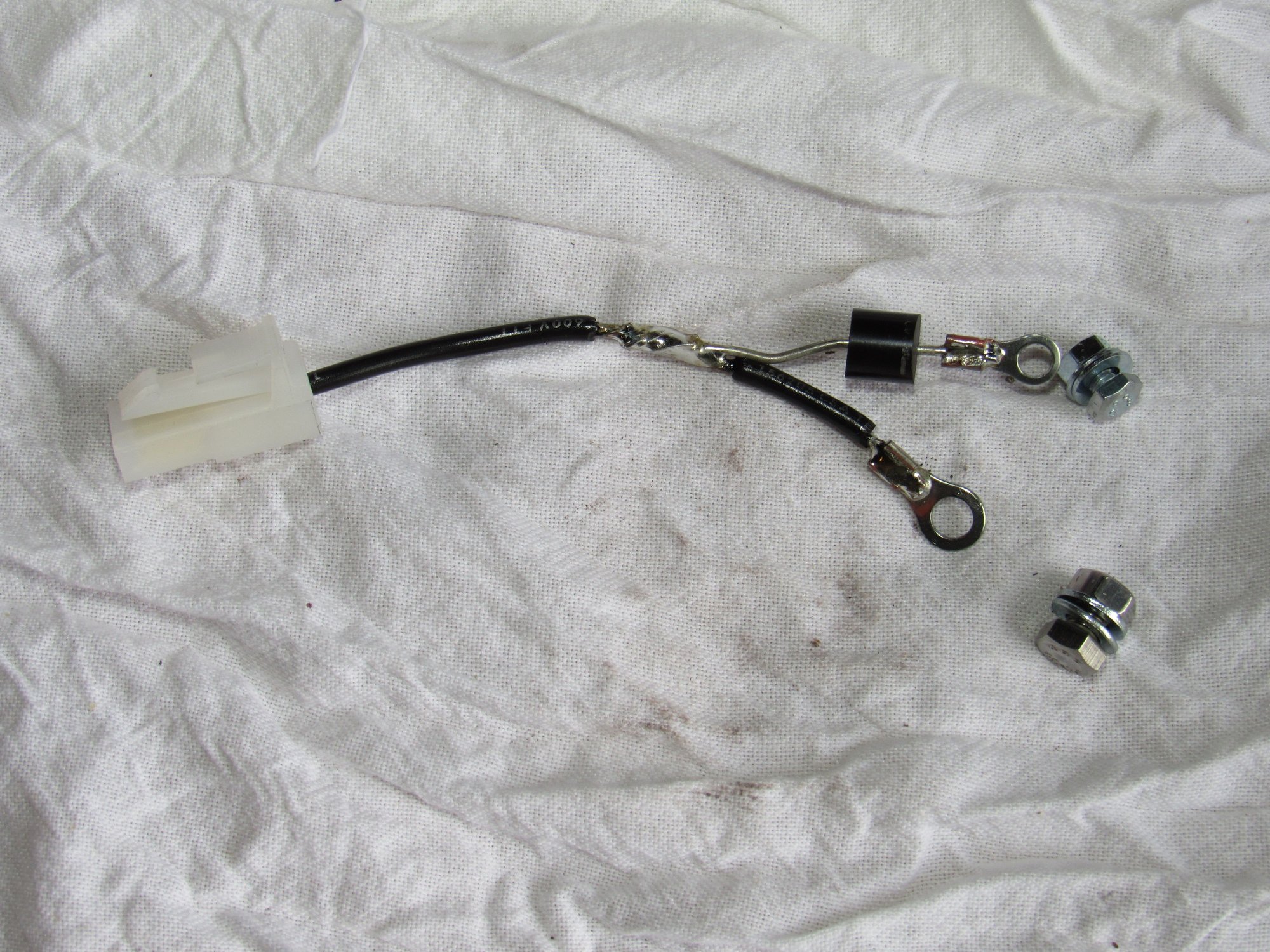
So I took up Dave's offer for the diode's (thanks again!) and after at least twenty starts over the past two months I can confidently say that the mini starter works great. I think the common failure of the stock starter is that the solenoid gets gummed up and stuck because I can only extend it out with a pry bar. Here is the harness I made. My only mistake is that the large ring terminal should go with the diode. I fastened the terminals to the engine harness with a 4mm and 5mm nut and bolt.
So I took up Dave's offer for the diode's (thanks again!) and after at least twenty starts over the past two months I can confidently say that the mini starter works great. I think the common failure of the stock starter is that the solenoid gets gummed up and stuck because I can only extend it out with a pry bar. Here is the harness I made. My only mistake is that the large ring terminal should go with the diode. I fastened the terminals to the engine harness with a 4mm and 5mm nut and bolt.
Wired the way you show it, that diode install is a waste. Absent the aux terminal that offers switched battery voltage while the solenoid is engaged, you need a relay to duplicate the function. It's essentially wired in parallel with the starter solenoid, so the trigger 50 lead closes the relay as it engages the solenoid. Then battery lead connects to the relay contact (30), other contact is the connection to the ignition resistors.
Wired the way you show it, that diode install is a waste. Absent the aux terminal that offers switched battery voltage while the solenoid is engaged, you need a relay to duplicate the function. It's essentially wired in parallel with the starter solenoid, so the trigger 50 lead closes the relay as it engages the solenoid. Then battery lead connects to the relay contact (30), other contact is the connection to the ignition resistors.
I'm looking at the wiring diagrams now and I don't understand how the stock setup works. I thought the black/yellow wire at the starter bypassed the resistors when energized but it leads directly to them.
During normal engine running the coil is fed from the transistor unit through BOTH resistors.
During cranking the black/yellow wire is energized and bypasses the 0.4 ohm resistor but is still feeding the coil through the 0.6 ohm resistor.
With that said, I don't see how my little harness does not accomplish the same thing?
When the starter is engaged the blk/yel wire is energized through the diode is it not?
The original system dumped current to the ignition without all the voltage drop between the starter end of the battery terminal and the end of the wire from the 50 circuit that you are using, plus the 0.7 Volt drop through the silicon diode. The idea of using the same source through a small relay means the ignition box and coil see the same voltage while cranking that they would in normal run condition.
For grins, connect your better DMM to measure coil voltage. Take a reading with and without your piece connected, and see if the volts while cranking are any different. I predict that there will be virtually no difference. Now run a short heavy jumper between the battery terminal on the starter directly to the black/yellow wire, and test again while cranking. Voltage at the coil will be higher than the previous readings. Now install the relay to duplicate the bypass function but only while the starter is engaged.
During normal engine running the coil is fed from the transistor unit through BOTH resistors.
During cranking the black/yellow wire is energized and bypasses the 0.4 ohm resistor but is still feeding the coil through the 0.6 ohm resistor.
With that said, I don't see how my little harness does not accomplish the same thing?
When the starter is engaged the blk/yel wire is energized through the diode is it not?
I agree with Alex. I actually had an OEM starter that did not energize the yellow/black wire. The car started, but would die as soon as I released the key. The starter has a DPDT (?) relay that was faulty. New OEM starter fixed it for years. The simpler hookup of this mini-starter eliminates that possibility. (I'm working from memory, so I might have mis-stated some of the above, but it's mostly right.)
Dave
The original system dumped current to the ignition without all the voltage drop between the starter end of the battery terminal and the end of the wire from the 50 circuit that you are using, plus the 0.7 Volt drop through the silicon diode. The idea of using the same source through a small relay means the ignition box and coil see the same voltage while cranking that they would in normal run condition.
For grins, connect your better DMM to measure coil voltage. Take a reading with and without your piece connected, and see if the volts while cranking are any different. I predict that there will be virtually no difference. Now run a short heavy jumper between the battery terminal on the starter directly to the black/yellow wire, and test again while cranking. Voltage at the coil will be higher than the previous readings. Now install the relay to duplicate the bypass function but only while the starter is engaged.
Now I've got it through my head and it all makes sense. To reiterate, the yellow wire's only duty is to activate the starter solenoid and that is why it is smaller and uses a smaller ring terminal. When the solenoid is active it effectively connects the blk/yel wire to the thick primary battery cable, bypassing all other wiring in the car and the one resistor.
Done properly, instead of a diode, that wire on my harness should be a trigger for a relay between the blk/yel wire and a new wire run to the battery cable stud on the starter. Got it.
That should be simple enough to do but for now it starts just fine though it could be a problem with a lower battery charge. I will revisit.
OK. Thanks for the explanation. It works as is though, but will follow. That's a tough area for a relay, so might need to run from starter up to engine bay. OTOH with a waterproof relay, I could make a short lead and locate the device very near the starter. Like this:


 05-02-2018 | 12:02 PM