
Need Help With A Couple Of Electrical Issues...SOLVED!
 10-05-2011, 11:49 PM
#1
Addict
Rennlist Member
Rennlist Member
Thread Starter
MY 1993 GTS
Brake Pad Sensors- I've had this issue for a while and just delete the cluster warning at the combination switch after each time the car is started. I thought it may have been a bad sensor in the past and it just wasn't important enough for me to troubleshoot for the last few years. I've been doing some work to the car this summer and refreshed all of the brakes including new sensors. Low and behold, the BRAKE PAD SERVICE light comes on as it always did. Since the car is on jack stands and I have access to everything I figured I would tackle this issue once and for all.
First off, the sensors are good...cheeked them with a multi meter. Also checked the grounds at each wheel, even cleaned them just for the heck of it.(there would have been other warnings if a ground was bad) I broke out the wiring schematics and traced the wiring path. Of course we know its just a loop, but I wanted to test the continuity through all the sensors at T23, pins 15 and 16. Only issue is, I can't locate the terminal. Notes show T23 at the ABS unit, but it is not specific where that actually is. Anyone know? Of course, if there is no signal between pins 15 and 16, then it should be easy enough to locate the break in the line.
Now, providing the signal is unbroken between the two pins, what would be suggested as to the next place to track this issue down?
Incidentally, the wiring from the sensors also go to the cluster at Plug 4, Contact 9 (Brake Pad Wear Indicator 1) and Plug 3, Contact 1 (Brake Pad Wear Indicator 2) IIRC this leads also come from T23. That's pretty much the end of the wiring for the brake pad sensors.
Turn Signal Indicator- This is another ghost. I have no turn signal indicator light on my cluster. The bulb is fine. It's an LED that I changed over back when I did the LED conversion. It worked fine until I took the cluster out for a LED backlight upgrade. It's pole specific and I know it is correct as I methodically did a full check on the cluster lighting from the 4 plug contacts. So here is the weird part. With the circuit energized, (key in all but "0" position) turn signals work, but indicator light does not. Even with the Emergency Flashers engaged, indicator light does not work. All exterior lights work and blink/flash. If I turn the key to the "0" position (key in or removed), engage Emergency Flasher button the indicator light works. I thought maybe there was an issue with the combination switch, but that wouldn't explain why the flashers do not light the indicator.
Hopefully, I had given enough info for any of the "circuit heads" out there to help me troubleshoot these two minor problems.
Thank you in advance!
Last edited by 928ntslow; 10-09-2011 at 12:47 AM. Reason: Solved issue
 10-06-2011, 12:03 AM
#2
Drifting

Per Wiring diagram, connector T23 is located - Footwell at Left Side Panel
Usually, the cluster turn signal problem is when exterior lamps are upgraded to LED. To avoid this, rear turn signals should remain as incandescent or rear LEDs turn signals lamps added with load resistor. Front LED turn signals can be added without any problems. You never said if you did the external LED mod? So, I'd say your problem sounds like a bad cluster LED.
Usually, the cluster turn signal problem is when exterior lamps are upgraded to LED. To avoid this, rear turn signals should remain as incandescent or rear LEDs turn signals lamps added with load resistor. Front LED turn signals can be added without any problems. You never said if you did the external LED mod? So, I'd say your problem sounds like a bad cluster LED.
10-06-2011, 04:20 AM
#3

Hi Keith - not trying to be a smart ***, but why not just put an OEM indicator bulb back into the dash? Sounds like that might fix the problem pretty simply and I wouldn't think having an incandescent indicator flash v LED would make much of a different driving experience?
10-06-2011, 05:10 AM
#4
Addict
Rennlist Member
Rennlist Member
Thread Starter
Thanks for the response guys, but it seems you may not have read my post closely enough.
I know what the wiring diagram says as well as the notes (I actually have full sized blue prints from Porsche) Was asking EXACTLY where it was.
No exterior LED, very well aware of the light control module issue and as I had said, exterior lights work fine. There would be other warnings associated with exterior LED anyway.
The LED again is fine...has worked for over 3 years until I took the cluster out recently.
10-06-2011, 06:02 AM
#5
Under the Lift
Lifetime Rennlist
Member
Lifetime Rennlist
Member
Hi Keith:
T23 is NOT "at the ABS". Go back and look at the plug connections sheet in the wiring diagrams. It's inside the passenger compartment under the dash on the driver side near the outer wall. The chart gives the coordinates as 7dQ. It's a 21-pin connector. If pins 15 and 16 show continuity (I doubt they will) then the problem is somewhere between that and the instrument panel. The wiring diagram shows pin 9 on plug 4 and pin 1 on plug 3 at the instrument panel. You could check continuity there. But most likely there will not be continuity at pin 15 and 16 on T23. This gives you no clue as to where the problem is other than there is a break in the sensor loop between all the brake pad sensors. Note the ground wire has nothing to do with it. If all the sensors themselves test good then perhaps a pin is broken in one of the junction blocks.
T23 is NOT "at the ABS". Go back and look at the plug connections sheet in the wiring diagrams. It's inside the passenger compartment under the dash on the driver side near the outer wall. The chart gives the coordinates as 7dQ. It's a 21-pin connector. If pins 15 and 16 show continuity (I doubt they will) then the problem is somewhere between that and the instrument panel. The wiring diagram shows pin 9 on plug 4 and pin 1 on plug 3 at the instrument panel. You could check continuity there. But most likely there will not be continuity at pin 15 and 16 on T23. This gives you no clue as to where the problem is other than there is a break in the sensor loop between all the brake pad sensors. Note the ground wire has nothing to do with it. If all the sensors themselves test good then perhaps a pin is broken in one of the junction blocks.
10-06-2011, 11:27 AM
#6
Rennlist Member

Join Date: Jul 2002
Location: Deep in the Heart of Texas!
Posts: 3,267
Likes: 0
Received 5 Likes
on
4 Posts
I too am constantly flipping my control stalk due to spurious "Brake Pads Service" warnings.
Is there something one can do with the two wires (Plug 4, Contact 9 (Brake Pad Wear Indicator 1) and Plug 3, Contact 1 (Brake Pad Wear Indicator 2) going into the cluster to fool the system? I.e cut them, connect them together, etc.?
I know the condition of my pads quite well and don't need a dash warning, so content to just defeat this particular feature permanently (the next owner can check out the entire wiring harness if they want)
Trending Topics
10-06-2011, 02:35 PM
#8
Rennlist Member

 10-06-2011, 03:24 PM
#9
Addict
Rennlist Member
Rennlist Member
Thread Starter
Thanks Bill...the answer I was looking for. Yes, T23 to the cluster is a waste as a start to trouble shoot. Will report back.
Tom,as far as a defeat, you can probably just jumper (Plug 4, Contact 9 (Brake Pad Wear Indicator 1) and Plug 3, Contact 1 (Brake Pad Wear Indicator 2), off the top of my head without looking at the wiring diagram, at pins 15 and 16 at T23. You are just bypassing the circuit/loop out to the sensors. So, you may want to just snip and jumper on the sensor side of T23.
Bill, how bout the Turn Signal Indicator light...any thoughts?
Tony, thanks, hope all is well.
10-06-2011, 03:59 PM
#10
Under the Lift
Lifetime Rennlist
Member
Lifetime Rennlist
Member
No, that's one for Alan.
If others just want to eliminate the brake pad sensor warning, put a jumper wire across pins 16 and 15 on T23. That should work in 99% of the cases. This only applies to MY 90+.
Note that in MY 89 and before there are additional harness junction blocks just behind the top of the shock towers inside the engine compartment and in the spare tire well, and the circuit even passes through the CE panel. It does not go through the ABS plug, but rather a different plug, T19 above the CE panel. Check year-specific wiring diagrams.
10-06-2011, 08:36 PM
#11
Addict
Rennlist Member
Rennlist Member
Keith, here's the deal on the turn signal indicator and where I suspect you might have gone awry.
Have you ever noticed that your turn signal indicator (at least when key is in ignition on position) blinks out of phase with your turn signals? That's because it lights as a result of one side of the indicator bulb being at 12 V and the other side attached to the flasher's 49a terminal (i.e., the same terminal that drives the turn signals) being grounded through the various turn signal bulbs (and/or load resistors, if you have them, due to turn signal LED upgrades); the latter is the wire to the cluster (plug 4, terminal 3). What's significant here is that (again, when key is in ignition on position) that means that plug 4 terminal 3 turns on the turn signal indicator when it is grounded, not when it's at 12 V.
I just performed the same tests on my car as what you were describing, and my results are the exact opposite. Turn signal indicator lights (out of phase) with the turn signals / hazard lights perfectly when ignition switch is in not in position 0, but in position 0, it doesn't light (for hazards and/or single-side-locked turn signal). I can't remember whether it ever did light for the latter case (before I did the LED conversion to the instrument cluster).
As yours works the other way, I'm starting to suspect (can verify this if someone answers my question in the next paragraph) that the turn signal indicator might actually get driven two ways: one polarity when the ignition switch is in the 0 position, and the opposite way when the ignition switch is in the other positions.
I'd really like to know what that indicator light is supposed to do when the ignition switch is in position 0; perhaps not having it on anymore is a side effect of the polarized LED being used for the turn signal indicator. Can anyone tell me what yours does on your regular incandescent-bulb-for-turn-signal-indicator car?
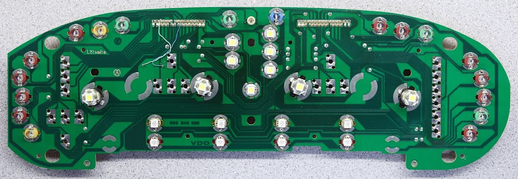
Anyway, Keith, shown below in the first photo are the polarities I've got marked for all the instrument cluster bulbs (as usual for my photos, click for a bigger version). Black marks indicate cathode (negative) side of each bulb position (I mark both the bulb base and the PC board).
Bottom line is that I believe you have your turn signal indicator LED inserted with the polarity reversed (at least to have it working like mine, which covers what are probably the most important cases)..

And... FWIW, there's some more information about some instrument-cluster-related anomalies when using LEDs in my write-up Converting Porsche 928 Interior Lighting to LEDs (still incomplete; maybe I'll work on it some more tonight ).
).
Note: If my hypothesis (about the turn signal indicator being driven with different polarities based on the ignition switch position) turns out to be true, a possible solution would be to try to squeeze another 3 diodes into the base of the B8.4d LED bulb assembly (wired into a full bridge rectifier). This would be a very tight fit, but might be doable.
Have you ever noticed that your turn signal indicator (at least when key is in ignition on position) blinks out of phase with your turn signals? That's because it lights as a result of one side of the indicator bulb being at 12 V and the other side attached to the flasher's 49a terminal (i.e., the same terminal that drives the turn signals) being grounded through the various turn signal bulbs (and/or load resistors, if you have them, due to turn signal LED upgrades); the latter is the wire to the cluster (plug 4, terminal 3). What's significant here is that (again, when key is in ignition on position) that means that plug 4 terminal 3 turns on the turn signal indicator when it is grounded, not when it's at 12 V.
I just performed the same tests on my car as what you were describing, and my results are the exact opposite. Turn signal indicator lights (out of phase) with the turn signals / hazard lights perfectly when ignition switch is in not in position 0, but in position 0, it doesn't light (for hazards and/or single-side-locked turn signal). I can't remember whether it ever did light for the latter case (before I did the LED conversion to the instrument cluster).
As yours works the other way, I'm starting to suspect (can verify this if someone answers my question in the next paragraph) that the turn signal indicator might actually get driven two ways: one polarity when the ignition switch is in the 0 position, and the opposite way when the ignition switch is in the other positions.
I'd really like to know what that indicator light is supposed to do when the ignition switch is in position 0; perhaps not having it on anymore is a side effect of the polarized LED being used for the turn signal indicator. Can anyone tell me what yours does on your regular incandescent-bulb-for-turn-signal-indicator car?
Anyway, Keith, shown below in the first photo are the polarities I've got marked for all the instrument cluster bulbs (as usual for my photos, click for a bigger version). Black marks indicate cathode (negative) side of each bulb position (I mark both the bulb base and the PC board).
Bottom line is that I believe you have your turn signal indicator LED inserted with the polarity reversed (at least to have it working like mine, which covers what are probably the most important cases)..


And... FWIW, there's some more information about some instrument-cluster-related anomalies when using LEDs in my write-up Converting Porsche 928 Interior Lighting to LEDs (still incomplete; maybe I'll work on it some more tonight
).Note: If my hypothesis (about the turn signal indicator being driven with different polarities based on the ignition switch position) turns out to be true, a possible solution would be to try to squeeze another 3 diodes into the base of the B8.4d LED bulb assembly (wired into a full bridge rectifier). This would be a very tight fit, but might be doable.
10-06-2011, 09:08 PM
#12
Addict
Rennlist Member
Rennlist Member
Thread Starter
Good point Ed, though I am 99% sure I have the polarity correct as this isn't my first rodeo on this. I did a write up way back when I first did the conversion if you remember. It IS possible that my preliminary testing prior to install was taken connected to the incorrect ground tab. Just strange that it worked with no issue for 3+ years and now not. I pulled every light individually and tested and reinstalled, so it could be 180d out. This will be about the 10th time I pulled that pod and cluster in the last week....PITA! lol
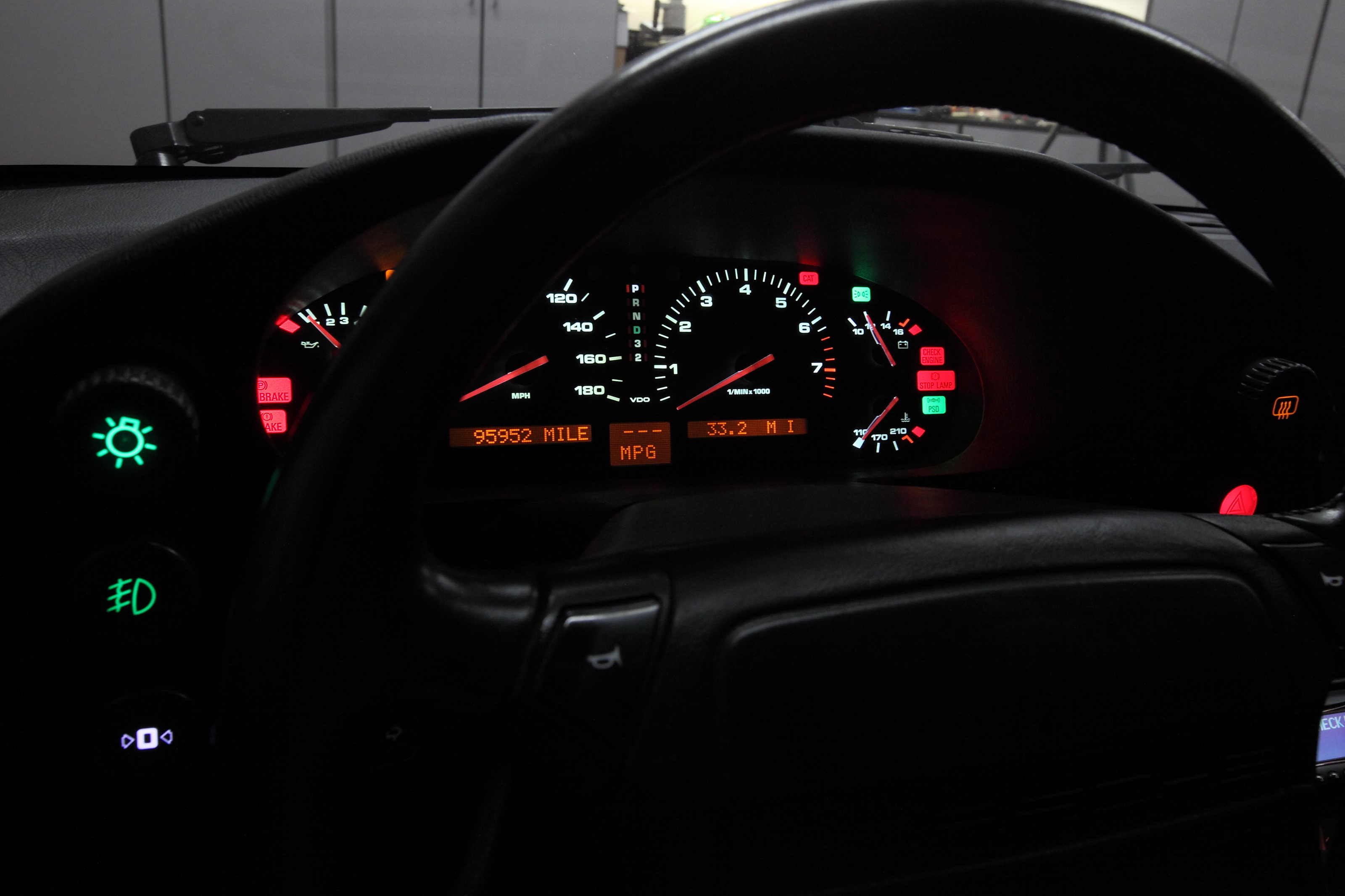
BTW, I like the LED's you are using. I considered those, but stuck to the projector beams. I see you have an auto, mines a manual so no need for the 2-P. I did however, change over the hi-beam, parking, turn signal and PSD since those are used regularly. On the back lit LCD, I just upgraded to VW 2w bulbs for the red display. (Led for PSD not shown in pic)

BTW, I like the LED's you are using. I considered those, but stuck to the projector beams. I see you have an auto, mines a manual so no need for the 2-P. I did however, change over the hi-beam, parking, turn signal and PSD since those are used regularly. On the back lit LCD, I just upgraded to VW 2w bulbs for the red display. (Led for PSD not shown in pic)
10-06-2011, 09:44 PM
#13
Addict
Rennlist Member
Rennlist Member

It IS possible that my preliminary testing prior to install was taken connected to the incorrect ground tab. Just strange that it worked with no issue for 3+ years and now not. I pulled every light individually and tested and reinstalled, so it could be 180d out. This will be about the 10th time I pulled that pod and cluster in the last week....PITA! lol
If it makes you feel any better, I've done the cluster in/out at least seven or eight times by now (out takes about 10 to 15 minutes, in typically takes at least half an hour since it's kind of hard to line up some of the bolts). And I've got at least one more coming. I've had some real reliability problems on the B8.4d-AHP bulbs; all the others have been reliable except for those. I've got a whole bunch of spares now, and I'm going to do a bench burn-in of them before I do any further replacements. I might even assemble some of my own bulbs (from spare part bases and raw SMD LEDs, resistors, and diodes) if that's what it takes.
BTW, I like the LED's you are using. I considered those, but stuck to the projector beams. I see you have an auto, mines a manual so no need for the 2-P. I did however, change over the hi-beam, parking, turn signal and PSD since those are used regularly. On the back lit LCD, I just upgraded to VW 2w bulbs for the red display. (Led for PSD not shown in pic)
 10-06-2011, 11:40 PM
#14
Addict
Rennlist Member
Rennlist Member
(This is a repeat of something I asked about a few posts back.)
Because I'm really trying to be thorough on my recommendations related to LED upgrades, I'd really appreciate it if someone with an '87 or later who hasn't done all sorts of incandescent-to-LED upgrading would do the following:
Without putting your key into the ignition switch:
Thanks in advance; please also tell me what model year your car is if it's not included in your Rennlist signature.
Because I'm really trying to be thorough on my recommendations related to LED upgrades, I'd really appreciate it if someone with an '87 or later who hasn't done all sorts of incandescent-to-LED upgrading would do the following:
Without putting your key into the ignition switch:
- Switch on your hazard lights. Does the green turn signal indicator in your instrument cluster blink? In phase or out of phase (i.e., at the same time on/off or the exact opposite) with your exterior turn signal lights?
- (With the hazard lights off again) Push your turn signal lever up or down. This should make your left or right turn signal (edit: that should be "marker", not "turn signal") lights turn on. Does the green turn signal indicator in your instrument cluster turn on when you do this? (edit: no, it doesn't/shouldn't, as although activated by the turn signal lever, it's not really the turn signals that turn on for this feature)
Thanks in advance; please also tell me what model year your car is if it's not included in your Rennlist signature.
Last edited by Ed Scherer; 10-07-2011 at 05:46 PM.
10-07-2011, 12:01 AM
#15
Team Owner
Ed to answer your question on my 88 it is stock .
with the haz switch pushed the green light flashes on with the outside lights
With the TS lever up or down right or left, the green TS light remains off the side markers do light
Keith try this start at the RR then LR then RF then LF remove the sensor connection to the car side of the harness add a jumper wire to the connection you will have to make 4 jumper wires with male connectors then start the engine after each jumper is added,
I hope that one of the jumpers will return proper function to the string please report back what you find.
NOTE the sensors have a different type of wire and teflon insulation, its quite possible that one of them has been damaged even though they test good remove each sensor from the string this should tell you where the damage is in the sensor string.
Also inspect the spare tire well for sensor connections.
I have found that the sensor insulation can be damaged and water will get into the insulation and corrode the wire till it breaks there may not be any visible damage to the insulation of the sensor wire insulation