


MAF and fuel pressure problems
Thread Starter
Nordschleife Master
Joined: Jan 2009
Posts: 5,609
Likes: 84
From: MA
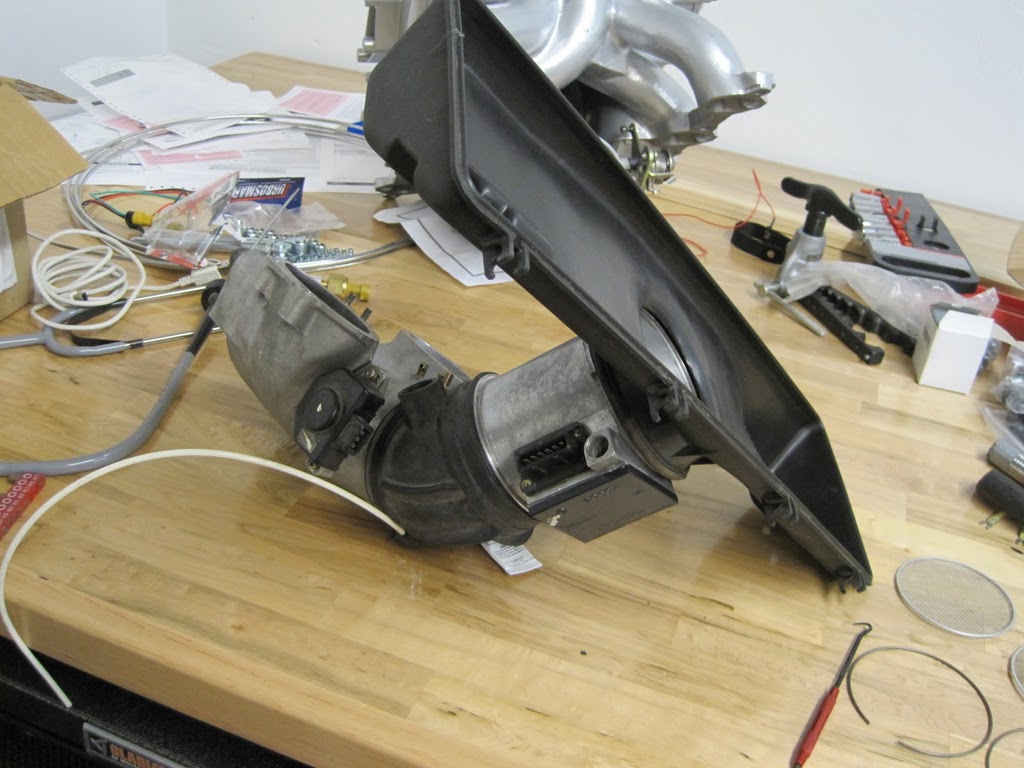
I looked a bit into the whole intake tract wround the MAF.
Here are some of my spare parts assembled. Ignore the orientation of the air box:
WholeTract.JPG
It's not obvious to me how to stake the MAF to the throttle body a way that is effective, cost effective, and looks factory. So my plan now is to groove the MAF sensor housing to help the boot stay on, and forget about other mechanisms.
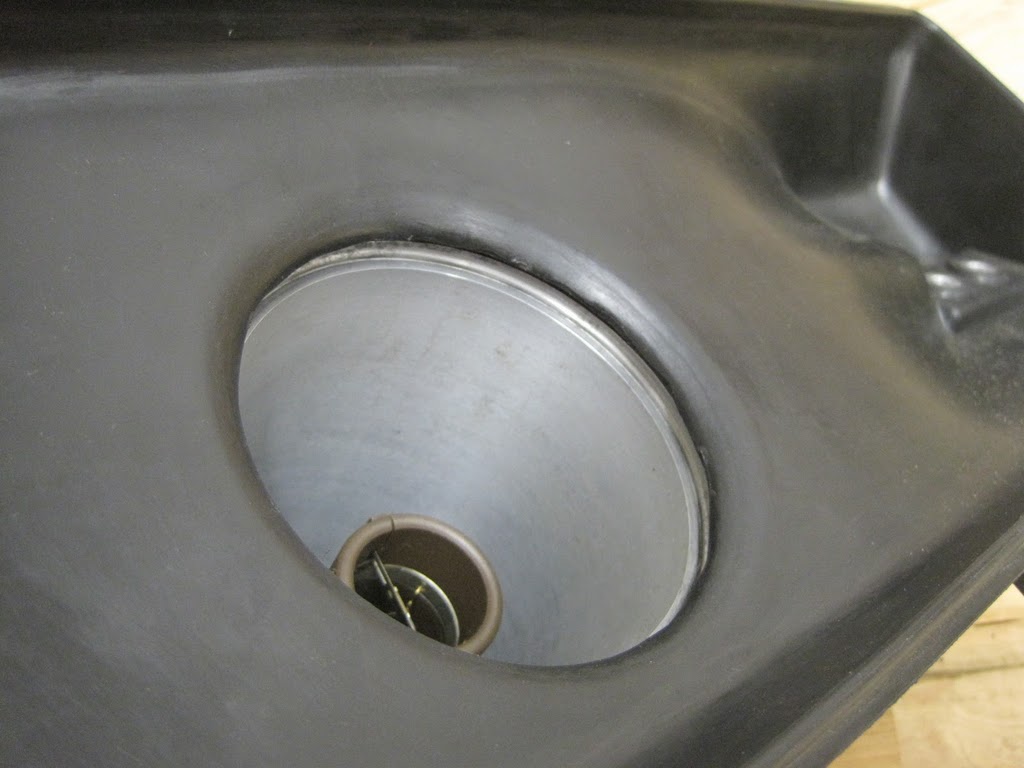
Then there's the question of the MAF screens. Here's what it would look like without the screens from the air flow perspective:
AirBoxWithoutScreen.JPG
Since everyone reading this has an internet access, google "maf screens" and you'll get hits after hits of complete drivel. Half of them end up with a conclusion that the screen is placed there to reduce power per a concealed agreement between the manufacturers and the EPA.
In any case, I did a ball-park Reynolds number calculation for the MAF sensor, assuming 10 cm diameter:
Diameter 0.1 m
Density 1.205 kg/m^3
Kinematic viscosity 15.11 (m^2/s)*10^6
Voltage sMAF kg/h Reynolds number
0.97 5.85 1136
1.28 7.68 1491
1.59 9.51 1847
1.89 11.34 2203
2.20 13.17 2559
2.50 15.04 2921
2.81 38.90 7557
3.18 97.28 18896
3.62 226.13 43925
According to this calculation, the flow type is transitional at idle and turbulent anything above idle. This applies to a straight pipe.
After exchanging some emails about this with people who know what they are talking about, the screen started making sense to me. Breaking up the possibly laminar flow at idle rpms may be helpful in making the sensor accurate. The mesh screen turns flow that may have very irregular size eddies into flow that has similar size eddies. How long the flow stays regulated after the screen depends on a number of things, such as screen properties and the air speed.
Recall that my car is already hot rodded to the point where minor MAF sensor errors need to be tuned against or the car will stall at 500rpm due to those MAF errors. Since I don't want the car to stall, I want to turbulate the flow. This is especially important in my case, because the temperature of the charge can vary dramatically (changuing the kinematic viscosity and thus Reynolds number) and because I can get the same mass air flow with either high boost, low volumetric flow or low boost and high volumetric flow. So the conclusion is that the upstream screen stays on.
Anybody understand what the function of the downstream/bottom screen is? The flow seems to be proverbial "water under the bridge" at that point...
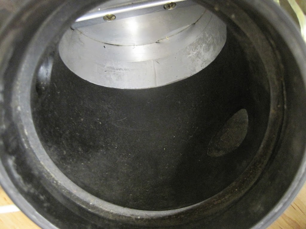
Here's another question about the silicone boot. When I put the stock rubber boot on, it forms a nice, smooth transition from the MAF housing into the boot and from the boot into the throttle body. The air will not know it passed over to the next component.
SmoothBoot.JPG
Based on my viewing of the silicone MAF boot, there would be a lip in the transition from MAF to the boot, since by my viewing the silicone boot doesn't have a depression for the MAF sensor housing or the throttle body. How are people using the silicone boot dealing with this? Or does that not have a material impact on flow?
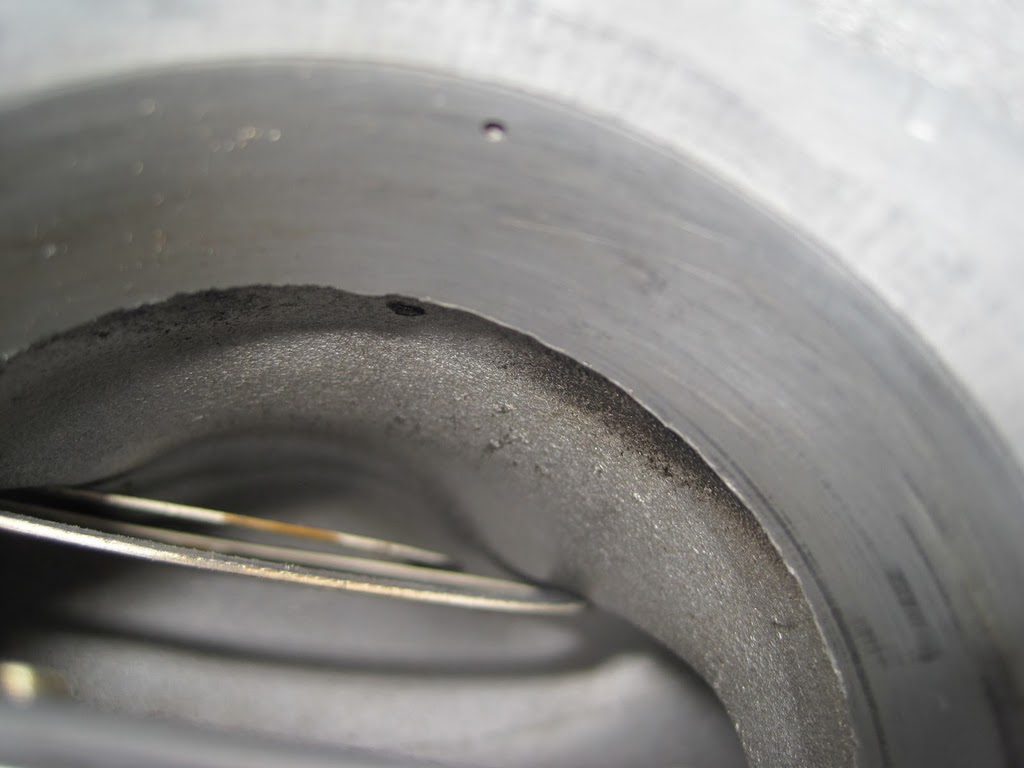
My final question / observation is that the throttle body has a big fat cast lip right after the throttle body. People with flow benches have worked on the main intake manifold piece, but I was wondering if anyone has any info about the lip inside the throttle body. If you open the throttle and stick your fingers inside the throttle body, you can feel a rough lip in the roof of the throttle body.
CastLip.JPG
Is this lip there by design, or is it just "cost effective" manufacturing by Porsche? It's on a slight short side radius in the flow path, so it could conceivable help flow as a vortex generator. I think it's unlikely, though. Should I smooth it out or not? Any flow-bench results on the topic?
Here are some of my spare parts assembled. Ignore the orientation of the air box:
WholeTract.JPG
It's not obvious to me how to stake the MAF to the throttle body a way that is effective, cost effective, and looks factory. So my plan now is to groove the MAF sensor housing to help the boot stay on, and forget about other mechanisms.
Then there's the question of the MAF screens. Here's what it would look like without the screens from the air flow perspective:
AirBoxWithoutScreen.JPG
Since everyone reading this has an internet access, google "maf screens" and you'll get hits after hits of complete drivel. Half of them end up with a conclusion that the screen is placed there to reduce power per a concealed agreement between the manufacturers and the EPA.
In any case, I did a ball-park Reynolds number calculation for the MAF sensor, assuming 10 cm diameter:
Diameter 0.1 m
Density 1.205 kg/m^3
Kinematic viscosity 15.11 (m^2/s)*10^6
Voltage sMAF kg/h Reynolds number
0.97 5.85 1136
1.28 7.68 1491
1.59 9.51 1847
1.89 11.34 2203
2.20 13.17 2559
2.50 15.04 2921
2.81 38.90 7557
3.18 97.28 18896
3.62 226.13 43925
According to this calculation, the flow type is transitional at idle and turbulent anything above idle. This applies to a straight pipe.
After exchanging some emails about this with people who know what they are talking about, the screen started making sense to me. Breaking up the possibly laminar flow at idle rpms may be helpful in making the sensor accurate. The mesh screen turns flow that may have very irregular size eddies into flow that has similar size eddies. How long the flow stays regulated after the screen depends on a number of things, such as screen properties and the air speed.
Recall that my car is already hot rodded to the point where minor MAF sensor errors need to be tuned against or the car will stall at 500rpm due to those MAF errors. Since I don't want the car to stall, I want to turbulate the flow. This is especially important in my case, because the temperature of the charge can vary dramatically (changuing the kinematic viscosity and thus Reynolds number) and because I can get the same mass air flow with either high boost, low volumetric flow or low boost and high volumetric flow. So the conclusion is that the upstream screen stays on.
Anybody understand what the function of the downstream/bottom screen is? The flow seems to be proverbial "water under the bridge" at that point...
Here's another question about the silicone boot. When I put the stock rubber boot on, it forms a nice, smooth transition from the MAF housing into the boot and from the boot into the throttle body. The air will not know it passed over to the next component.
SmoothBoot.JPG
Based on my viewing of the silicone MAF boot, there would be a lip in the transition from MAF to the boot, since by my viewing the silicone boot doesn't have a depression for the MAF sensor housing or the throttle body. How are people using the silicone boot dealing with this? Or does that not have a material impact on flow?
My final question / observation is that the throttle body has a big fat cast lip right after the throttle body. People with flow benches have worked on the main intake manifold piece, but I was wondering if anyone has any info about the lip inside the throttle body. If you open the throttle and stick your fingers inside the throttle body, you can feel a rough lip in the roof of the throttle body.
CastLip.JPG
Is this lip there by design, or is it just "cost effective" manufacturing by Porsche? It's on a slight short side radius in the flow path, so it could conceivable help flow as a vortex generator. I think it's unlikely, though. Should I smooth it out or not? Any flow-bench results on the topic?
Last edited by ptuomov; Sep 17, 2010 at 01:36 PM.
Thread Starter
Nordschleife Master
Joined: Jan 2009
Posts: 5,609
Likes: 84
From: MA
The hp loss from driving the turbos depends on what kind of turbine is being used. I would guess the loss would be between 5% and what a supercharger uses.
Thread Starter
Nordschleife Master
Joined: Jan 2009
Posts: 5,609
Likes: 84
From: MA
No matter whether you continue with stock boot or silicone, stock clamps or other, dump the screwdriver and use a long-shaft nutdriver or even a 1/4" drive with the flexi extension mentioned above.
The 1/4" drive tool adds the ability to use a torque wrench or torque-limiting screwdriver on the clamp. That will give you some basis for determining that the torque needed for correct clamping under boost and heat is more than the original clamp can muster.
The 1/4" drive tool adds the ability to use a torque wrench or torque-limiting screwdriver on the clamp. That will give you some basis for determining that the torque needed for correct clamping under boost and heat is more than the original clamp can muster.
- MAF housing pops out of the boot
- I overtighten the clamp
- Overtightened steel clamp cuts into the rubber
- Aluminium parts expand more than the steel clamp, cutting further
- Cuts in the boot spread out and the boot breaks
I've collected the following ideas so far to remedy this:
- Groove the MAF housing so that the MAF boot sinks in and will better hold with sensible clamp torque
- Use spring loaded Breeze clamps which keep the load about constant even if the aluminum parts expand more than steel
- Use a flex extension and a troque wrench to tighten the clamps to a known torque value, instead of to as tight as one can with a screwdriver and bloody hands
Thread Starter
Nordschleife Master
Joined: Jan 2009
Posts: 5,609
Likes: 84
From: MA
If I run out of problems, I'll do just that: Dual draw-thru MAFs feeding an ITB system! Right now, I am fully stocked with little projects so that will have to wait.
Race Car
Joined: Dec 2003
Posts: 4,477
Likes: 5
From: Atlanta, GA
Where did you get an S/C'ed car needs to run 11.5:1 AFR to be optimal? Mine is running well at ~12.5:1. Increasing fueling to 11.5:1 gives me almost no room to add additional ignition timing.
Dan
'91 928GT S/C 475hp/460lb.ft
Dan
'91 928GT S/C
475hp/460lb.ft
Thread Starter
Nordschleife Master
Joined: Jan 2009
Posts: 5,609
Likes: 84
From: MA
I don't think turbo or supercharged engines are much different in this respect. It may be that increasing boost imposes a larger power cost on a supercharged engine, but I think this effect probably has a small impact on the optimum. That's a pure guess.
If one doesn't push it to the limit by increasing boost as much as possible, I assume/guess that the car will run better leaner than 11.5 AFR.
Recall that these are only guesses, based on just a little bit of data from my engine. This is not some universal thruth that will apply to all engines. And I might learn down the road that even my engine wants something different.
What do you mean by "Increasing fueling to 11.5:1 gives me almost no room to add additional ignition timing"?
Last edited by ptuomov; Sep 17, 2010 at 09:31 AM.
Rennlist Stories
The Best Porsche Posts for Porsche Enthusiasts

Porsche's Top 5 Most Questionable Naming Decisions
Verdad Gallardo
Pogea Racing's 964 Porsche 911 Reimagination Stands Out in a Crowded Field
Verdad Gallardo
6 Convertible Top MYTHS Most People Don't Understand!
Michael S. Palmer
2026 Porsche 911 Club Coupe is Spectacular, And Everything Wrong with the Porsche Market
Joe Kucinski
Talos Takes Your 991 Porsche 911 GT3 to the Next Level for a Cool $1.13 Million
Verdad Gallardo
9 Vehicles Porsche Helped Engineer that Aren't Porsches
Verdad Gallardo
9 Features and Characteristics That Only Porsche People Understand
Verdad Gallardo
I've Written 500 Rennlist Articles: Here's How Porsche Has Changed Along the Way
Joe Kucinski
10 Most Unnecessary Porsches Ever Built (And Why We Love Them)
Verdad GallardoRace Car
Joined: Dec 2003
Posts: 4,477
Likes: 5
From: Atlanta, GA
Dan
'91 928GT S/C
475hp/460lb.ft
Thread Starter
Nordschleife Master
Joined: Jan 2009
Posts: 5,609
Likes: 84
From: MA
So with my current configuration, it is not as easy to change the boost at will like it is with a turbo. In fact, I have pretty much reached the RPM limit of the M112, so at this point I am focusing on optimizing my car for the current boost level. What I have found is if I tune for a 12.5:1 AFR and tune ignition to avoid knocking, then going down to 11.5:1 AFR, I can only increase the advance very little before it starts knocking again. I haven't really done this in a scientific manner recording everything, but at least in the case of my configuration, that one extra rich point in AFR only allows for maybe 1 or so degree maximum of extra advance before it starts to knock again.
So, given the current tune, current boost ,and peak power rpm, you're moving at the constant knock probability curve with a slope of 1 point of AFR for 1 degree of timing? And the maximum torque is obtained at AFR 12.5? That's interesting to know.
Race Car
Joined: Dec 2003
Posts: 4,477
Likes: 5
From: Atlanta, GA
That makes sense to me, not that I know what I am talking about. I have grand total of two months of experience in tuning cars.
So, given the current tune, current boost ,and peak power rpm, you're moving at the constant knock probability curve with a slope of 1 point of AFR for 1 degree of timing? And the maximum torque is obtained at AFR 12.5? That's interesting to know.
So, given the current tune, current boost ,and peak power rpm, you're moving at the constant knock probability curve with a slope of 1 point of AFR for 1 degree of timing? And the maximum torque is obtained at AFR 12.5? That's interesting to know.
 The difference is so small I doubt I would be able to feel it, but I think it's running better at 12.5.
Dan
'91 928GT S/C
475hp/460lb.ft
Thread Starter
Nordschleife Master
Joined: Jan 2009
Posts: 5,609
Likes: 84
From: MA
Ideally, you'd have the constant-knock-probability iso-curve for each rpm at max boost and WOT. Once that is done, you could then go and rent a dyno and find the point that makes most torque from each rpm specific iso curve.
Rennlist Member

Joined: Jun 2005
Posts: 10,583
Likes: 1,030
From: Oman
Tuomo,
Some interesting thoughts in this thread. I presume from your power output that you are pushing the turbo's quite hard- 15+ psig of boost? You saw what happened to George's boot so going silicon makes a lot of sense given the effect on something that was designed to handle vacuum not pressure.
On the MAF screen design much has been written but I reckon most of it is tosh. I believe the screens are there for mechanical protection and nothing else- on the inlet side the stock paper filter may not offer much resistance to a small stone flying through there. On the outlet side the best theory I could come up with some 10 years ago was that it may act as a flame arrestor in the event of a backfire but it did not stop me from removing that screen and I still run that way. If I was running a K&N I might even remove the inlet screen, but then I do not believe in those things on a stock air box having seen oil dribbling down into the MAF and accumulating on the central ferrule [and that was before I overoiled the thing after cleaning it].
With respect to your calcs on Reynolds number- appreciate they are rough but you would need to compensate density for air pressure changes under boost [assuming you have not done so]. I would expect air flow through this conduit to be turbulent other at the lowest flows but as I read it, your model does not quite suggest that given the Reynolds number and the voltage outputs from the super MAF. Remember turbulent flow only starts at Re 4000, below that it is transitional and then laminar below Re2000. Even so, I believe that is irrelevant as the algorithm used by Bosch to compute mass air flow through the MAF will have taken this into consideration.
Whether or not scaling errors are introduced when moving to a super MAF is something John might have a view on but even then with the Sharktuner and exhaust gas analysis it is somewhat irrelvant I suspect.
To help you keep the boot on [when you have procured a silicon boot] you might consider using silicon RTV to seal/secure it. It would probably be a PITA to remove it but then how often do you need to remove the MAF? Easy enough to deal with when removing the inlet manifold which is not exactly a huge job. A strong clamp over the top tightened with a 7mm socket [or whatever the size is] using a good quality jubilee clip or something better [if there is such a thing and you can get in there to tighten it].
On the AFR front, I understand running richer is generally there to help cool the exhaust valves but then I am sure that Herr Kuhn has that covered with you. It does help to improve knock perforamce but not spectacularly so. Running rich does not rob power in the same way as running too lean and running a bit rich is also a "relatively safe condition" to be in. Most articles I have read on turbo charging suggest an AFR in the region of 11.5 to 12 "for safety" and tht seems to be pretty much universally accepted.
On a naturally aspired engines Louie derives max power at 13.5 which he attributes to the [relatively good] efficency of the head design. What happens under boost and whether that translates, is an interesting point for you chaps to develop if you are going after every last bit of power and are [relatively speaking] not too worried about the outcome.
Thread Starter
Nordschleife Master
Joined: Jan 2009
Posts: 5,609
Likes: 84
From: MA
Overall, I am well above my limits in terms of understanding of air flow and fluid dynamics. Would have to buy a flow bench and hit the books to move forward.
So far, the best *internet* source on the topic of screens is this: http://navier.stanford.edu/bradshaw/tunnel/screen.html It has links to old academic papers and generally makes sense. Also the domain name inspires confidence as far as the theory goes! ;-)
My reading of this material is that without screen the flow from the airbox may have large eddies and laminar sections. These will lead to inconsistent measurements, the MAF signal may at some constant flow conditions display a saw-tooth pattern if the screen is not installed. It's therefore not true that one can necessarily just sharktune around the problems caused by removing the top screen.
Screen or honeycomb will break up both laminar flow and large eddies into small eddies. The pressure variation across the screen upstream are also smoothed downstream. There are some photos of smoke wand experiments and the like on the web. How long it takes for the large eddies to reappear in terms of the flow path length is a mystery to me.
I have an especially difficult problem of potentially getting the same air flow (in kg/h) at the same rpm in two different ways: Low boost, high volumetric flow or high boost, low volumetric flow. Therefore, instead of thinking about removing the screen, I am thinking about leaving the screen in AND adding a honeycomb stabilizer to the air box exit.
The best theory so far that I've heard is that the stock breather system dumps oil every now and then into the MAF boot elbow. If this oil splashes to the MAF, there will be major problem. The screen is there to break up the splashes.
With respect to your calcs on Reynolds number- appreciate they are rough but you would need to compensate density for air pressure changes under boost [assuming you have not done so]. I would expect air flow through this conduit to be turbulent other at the lowest flows but as I read it, your model does not quite suggest that given the Reynolds number and the voltage outputs from the super MAF. Remember turbulent flow only starts at Re 4000, below that it is transitional and then laminar below Re2000. Even so, I believe that is irrelevant as the algorithm used by Bosch to compute mass air flow through the MAF will have taken this into consideration.
When interpreting my Re computations and MAF voltages, it's useful to keep in mind that both MAF and superMAF output about 2.8 or so volts at idle. The Re by my computations is already over 7000 that point.
You may be correct that the MAF housing's Re number may be irrelevant since the Bosch sensor was designed to work with that size and those flows. It's useful to also remember that the Bosch sensor WAS DESIGNED TO BE USED WITH THE SCREENS ON! If we are going to screw around and modify the sensor and the sensor housing, we have to understand what's going on and with modifications we can no longer rely on Bosch. I don't think their design requirements included bozos removing screens... ;-)
To help you keep the boot on [when you have procured a silicon boot] you might consider using silicon RTV to seal/secure it. It would probably be a PITA to remove it but then how often do you need to remove the MAF? Easy enough to deal with when removing the inlet manifold which is not exactly a huge job.
The clamps are important. Overtorquing the clamp and heat, in addition to pressure, were likely reasons for the stock MAF boot failures. That's a pure guess. I got a great suggestion from someone on clamps: Using those Breeze clamps which keep the load about constant even with differing thermal expansion. I am going to take some measurements and then see if I can fit one in and groove the MAF with a wide enough groove to fit one in.
Under the Lift
Lifetime Rennlist
Member
Lifetime Rennlist
Member
Joined: Mar 2002
Posts: 18,648
Likes: 52
From: Buckeye, AZ
Tuomo: I don't think the lack of a flush step in the ends of the silcone boot does anything measurable to flow, especially under boost and considering all the other lips and irregularities in the intake. Look at the way the throttle housing fits to the manifold.
BTW, I think George and I have some good ideas as to why he is heating the fuel and losing fuel pressure after having the system looked at by an FI pro at the Silver State Classic, but we won't know for sure for a while.
BTW, I think George and I have some good ideas as to why he is heating the fuel and losing fuel pressure after having the system looked at by an FI pro at the Silver State Classic, but we won't know for sure for a while.