When you click on links to various merchants on this site and make a purchase, this can result in this site earning a commission. Affiliate programs and affiliations include, but are not limited to, the eBay Partner Network.
(The "new" iPhone web interface to edit posts is so effing bad that I'm going stop editing these posts. It's comically bad.)
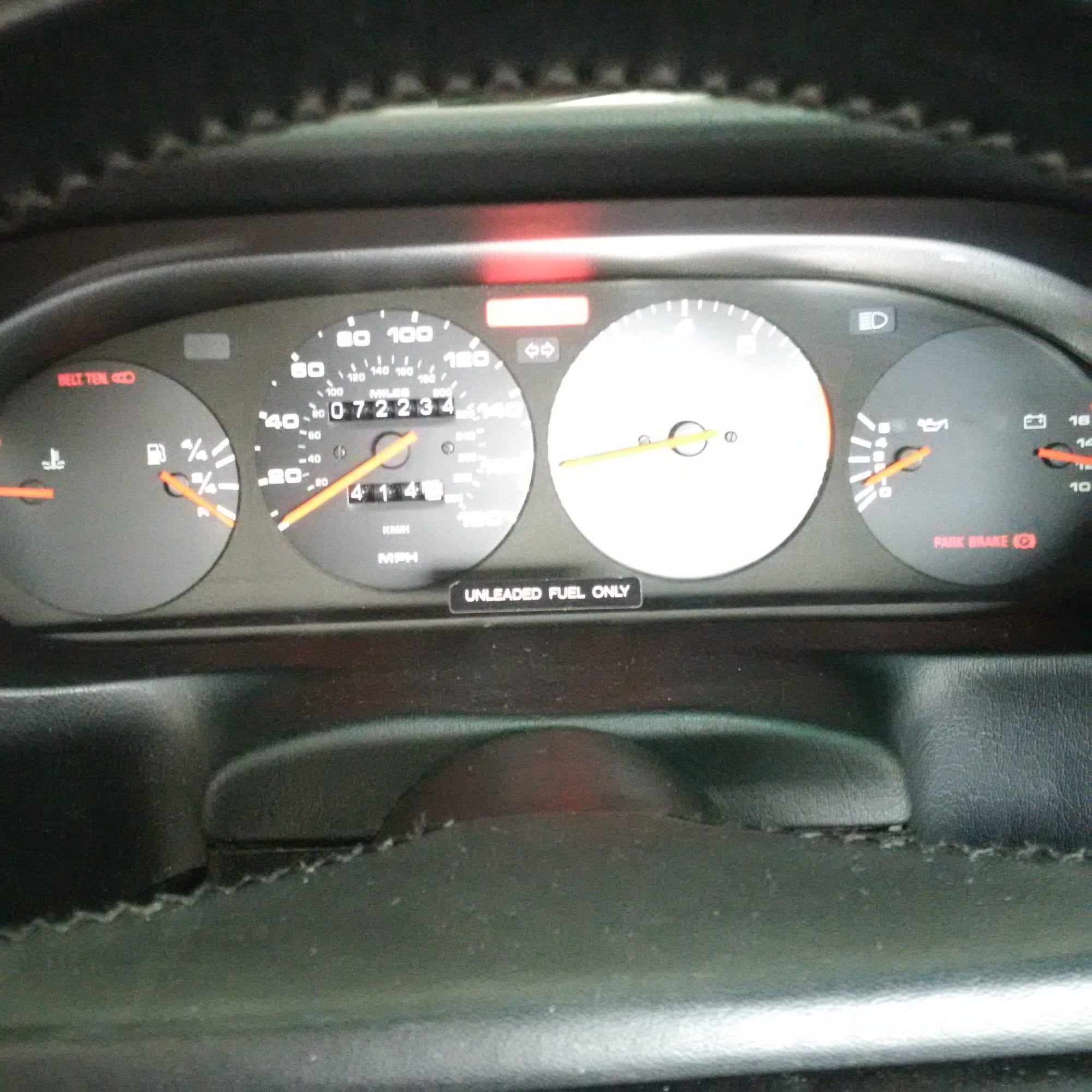
The engine was test fired. Ran for 30 seconds. Oil pressure as expected. No known issues at this point.
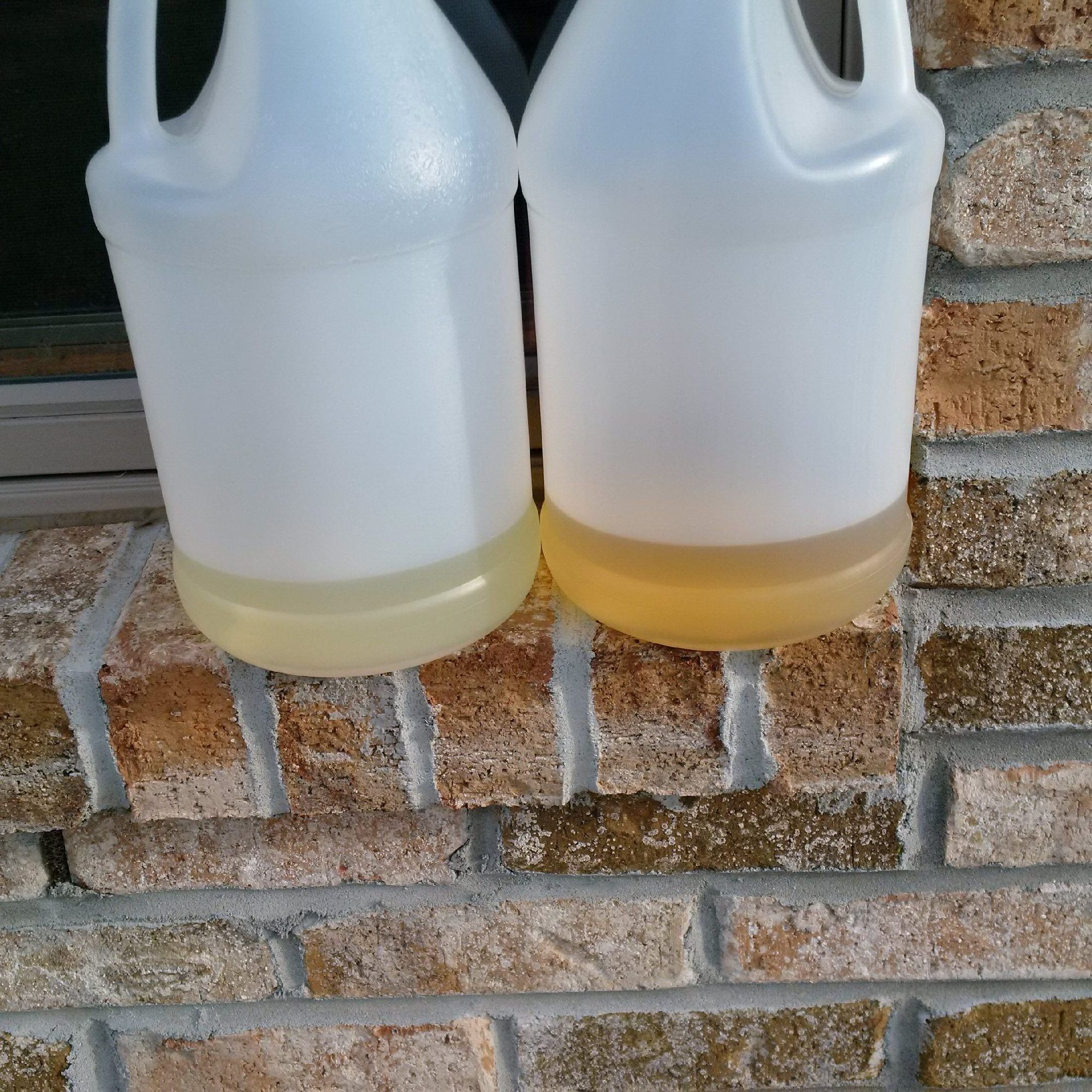
These are the before and after urine samples of the Anger Management production staff straddling the production dates of the Lindsey Lohan guest appearance episode:
Or new gas vs. old stale gas from the car's tank.
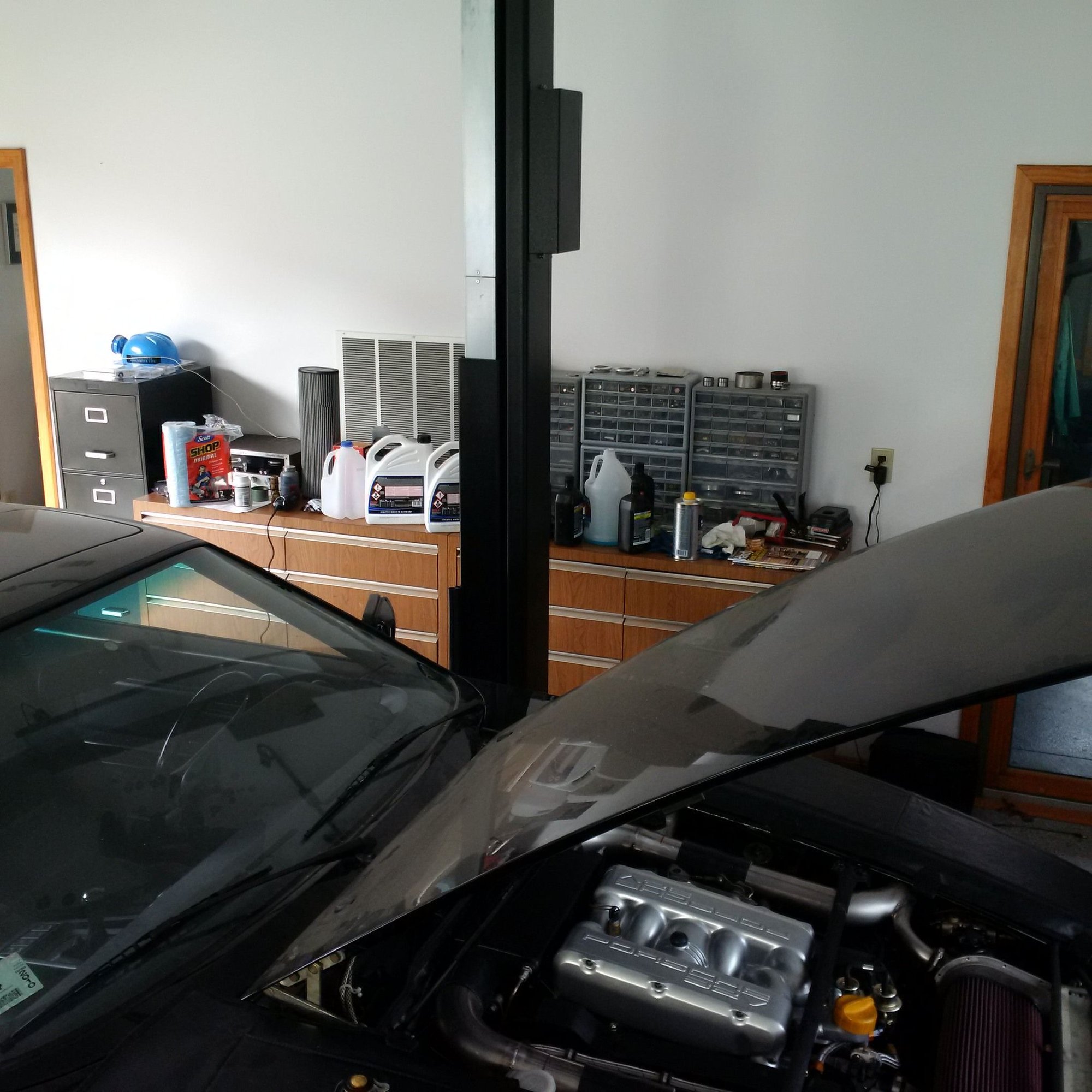
We've got a gates racing belt, PAC valve springs, and porkentensioner in the motor. The tensioner warning light wire will be grounded.
It's going to look pretty good in terms of aesthetics, even without coatings and the air filter cover it's pretty as it is.
The next steps are to run the engine with high detergent oil to clear out the assembly lube etc., then break it in on a dyno with conventional break in oil, and finally fill it up with high viscosity synthetic oil.
Yes. Most basic mechanical problems would have been exposed already at this point.
The car needs the exhaust on before it can go on the hub dyno for an hour or so. The plan is to run it thru a break-in algorithm that varies the rpm. Staying above 1500 rpm for the cam break in and the over the session extending the maximum rpm and load.
I looked at some old GM and Chrysler break in algorithms and it appears there's no rocket science there: just keep varying everything more or less randomly above some minimum rpm and increase the load and max rpm as you get further in the process. My casual reverse engineering of it was that minimum rpm constraint is for the cams and the maximum load constraint is for the piston rings. But that opinion and $2 gets you a cup of coffee at the Starbucks!
My thoughts on break-in are the following. This is not facts, just opinions! First, it makes sense to flush out contaminants from the engine with the first batch of oil. Ideally, the engine doesn't have any contaminants. If you've attained the ideal, there's no need. Some might even argue that the detergent package removes some of the protective phosphates from sliding surfaces. But in some cases, the engine may for example have been stored for a couple of years, contrary to plans, and who knows how assembly lube stores over years? Second, it makes sense to make sure that the oil is getting everywhere in the engine right at the start up. Third, it makes sense to keep the rpm high enough (say over 1500 rpm) for a while to protect the cam lobe noses, which are most sensitive to oiling (think thru the oil film wedge geometry between the lobe and the lifter) and also most stressed at low rpms. Fourth, the load and rpms have to be high enough and varying enough that the piston rings aren't stuck and rotate freely while the engine runs. Fifth, and finally, when reading about other people's break-in procedures, consider the source! Even if the person writing knows what they are talking about (I don't...) and isn't trying to sell you some product or service (I ain't), it's still the case that most of the break-in procedures probably don't directly apply to our engines with dohc direct-acting bucket lifters and low spring loads, Ferrocoat pistons and Alusil bores, etc.
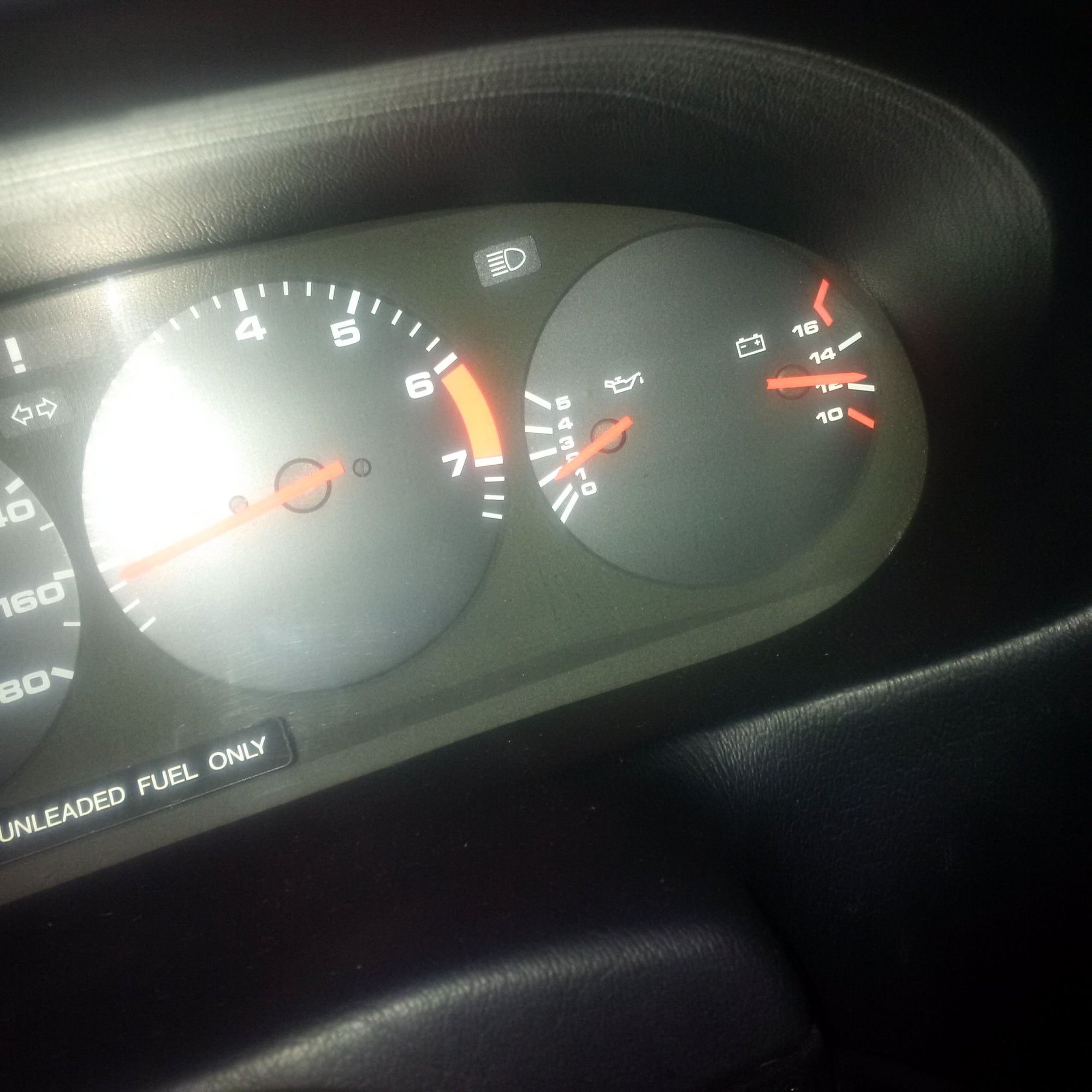
The oil pressure is "2 bar" (or should I say two bars as in marks!) by the gauge at idle with hot 15-40 oil, not that its idling a lot in its current state:
The filter will be inspected tonight to see what the first flush got out of the engine. New filter and new oil are in.
On other big milestones, my youngest got to ride a board for the first time. She's already a good skier at four years old, but can't wait to do everything that the older sisters are doing:
With the new bigger cams, heads ported to produce higher low lift low, and lower static compression, the idle vacuum is down somewhat. Compared to stock S4 with apples to apples measurement, were seeing a 24% drop in idle vacuum. The idle is fine at the GT idle rpm, and the larger camshaft overlap should pay some dividends at low mid-range rpms right before the turbos have spooled.
The "high detergent oil" "flush run" produced a very clean oil filter. The amount of metal particles is consistent with piston rings seating. No evidence of anything undesirable happening with the cams. Or engine bearings for that matter, although it'll take longer to learn anything about the bearings.
Bigger cams with more duration always reduce idle vacuum. Ported heads has no influence on the vacuum.
�ke
Bigger cams with more duration always reduce idle vacuum. Ported heads has no influence on the vacuum.
�ke
These heads were ported assuming that they would be used with the stock S4 cams. (This didn't end up being the case, as better cam options became available.) Consequently, the heads have higher than stock low-lift flow. In my opinion, this higher-than-stock low-lift flow acts analogously to increasing camshaft duration. That's the reason why they were ported the way they were ported -- to make up for overly conservative S4 cams. Therefore, I think the way these heads were ported does impact the idle vacuum. By how much, I don't know.
If one were to port the heads for big cams, maximizing the high lift flow and intentionally keeping the low-lift flow down, then I'd agree that porting probably shouldn't influence idle vacuum much. That's because low-lift flow wouldn't really change that much because of that kind of porting job.
The "blue engine" in the car now that was just fired up and is being broken in was built for me by a person who's sadly no longer interested in 928's. A couple of rennlisters helped him. Any of the people involved are welcome to chime in, depending on the interest level and the tolerance for the Rennlist noise. While the reliable solutions in this engine were recommended and in some cases designed by the builder, I requested a number of unproven and speculative changes to those. So far, things are working as intended, knock on wood. However, I fully expect some of the speculative solutions that I requested to yield some unexpected results -- how unexpected and at what point is an open question. If something breaks on this engine, that's from me. The parts that are reliable are from the builder.
As we're breaking in the engine and I made some comments about oiling, here are a couple of words and pictures about the blue engine oiling. I've already posted about the crankcase breather system and various air-oil separators related to that system. There are important oiling improvements inside the engine as well.
The objectives with the oiling system were to get oil pumped to all required surfaces at the desired pressure, do that without unnecessary drag due to pressure losses in the passages, return the oil to the sump promptly while avoiding mixing of air in the oil, keep the oil in the sump such that the pickup doesn't suck air during external g-forces that street tires can produce, and make the oiling system as robust as possible to the inevitable short-term events during which air gets into the pressure system for some reason. Since this is a turbo engine, ability of the engine to withstand prolonged periods of very high rpms was _not_ one of the design requirements.
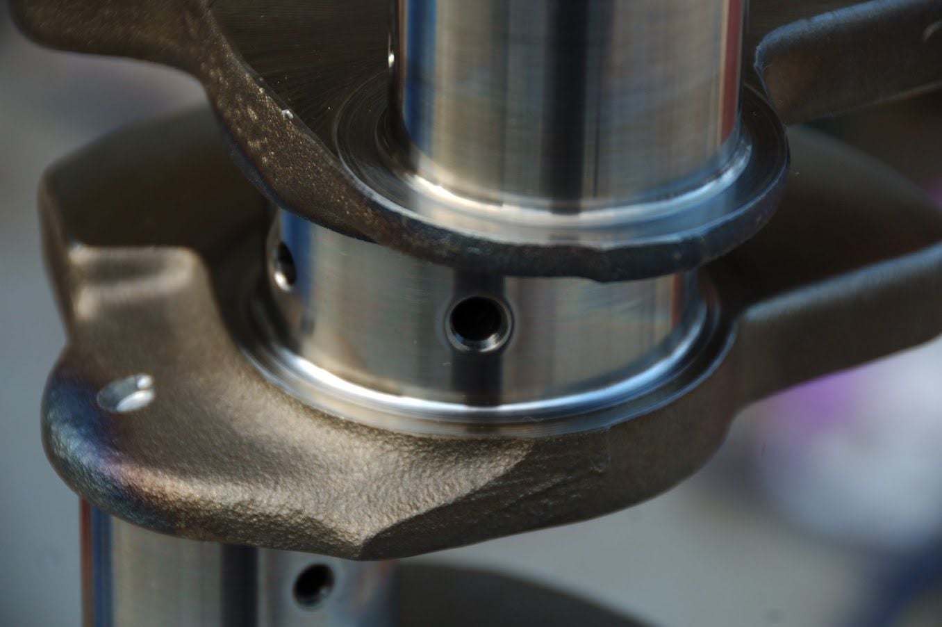
Some examples of internal oiling modifications below.
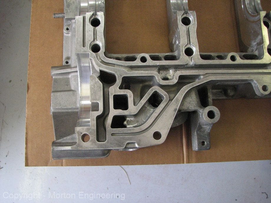
The casting slack was removed from the oil passages and the turn radiuses increased. As you can see from the photos, the diameter of the sections that serve the function of metering orifices was kept constant:
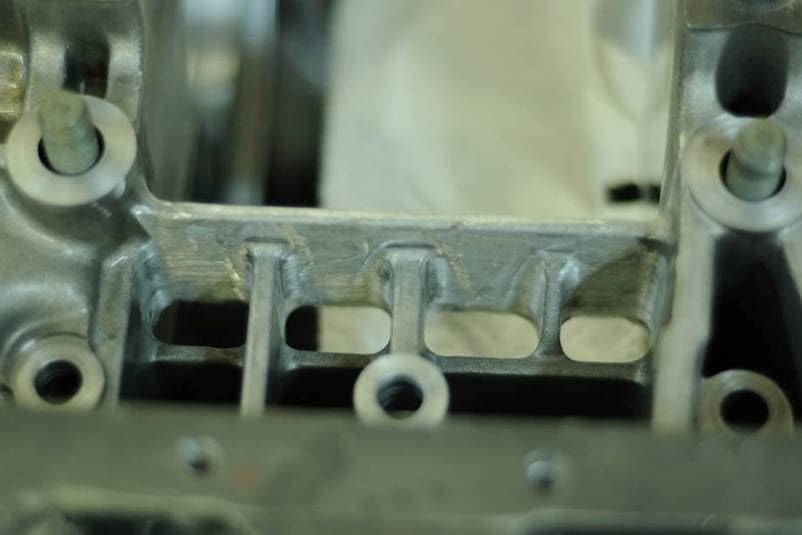
The casting slack was also removed from parts of the girdle and block that could potentially inhibit oil return to the sump:
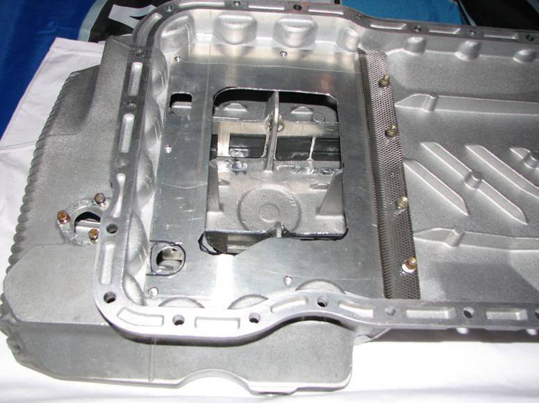
A heavily modified I-J windage tray system is in the sump. The system is heavily modified for many reasons, including the fact that this engine has an oil-pan spacer. The purpose of the system is to facilitate oil drain to the sump without the oil hitting the crankshaft, keeping the oil from the crankshaft due to external g-forces to which the engine is subjected, and preventing the piston pumping pulses from causing too much trouble in the sump:
The oil pan is baffled with trap doors that are similar to the rubber flaps used by BMW:
To the extent that air gets into the oiling system and then separates in the passages, the system was made more robust to this by web-drilling the crankshaft to connect all the rod journal oil passages to each other:
Over the last two decades, there have been many debates about crankshaft oil drillings. I would even say that there has been much confusion on the topic, and I've probably been at times both the cause and the victim of this confusion! My current thinking on the crankshaft oil passages is the following. As long as the oil in the pressurized supply galley is free of air, the 928 crankshaft drilling works great at the intended engine operating speeds. The problems start appearing with air in the oil and/or at very high rpms (well past the stock GT redline). The air in the oil gets separated by the block passages and disproportionately allocated to main that supplies the 2/6 rod journal in the stock crankshaft. The crankshaft in the blue engine is drilled to mitigate this problem. The additional passages connect all the rod journals and all the mains to a single interconnected web. One of the intended benefits of this web drilling is to undo some of the air-oil separation and more evenly distribute the oil (and air) to rod journals. This web drilling doesn't do much to reduce the oil pressure required to supply the mains at high rpms, because the passages still run thru a low-radius route close to the crank centerline. At high rpms, this crankshaft still requires very high oil pressure to overcome the centrifugal force of the main journal. This is fine for a turbo engine that isn't intended to run much above the stock GT redline, and will make peak power well below that engine speed.
Let me conclude with some partly original, and completely unverified, thoughts on oil selection:
I'm not sure whether breaking in the engine with conventional oil has any scientific basis at this point. It's probably just marketing of special break in oils, old habits, and superstition. Every high end car engine gets broken in with a fully synthetic oil at the factory today. But all the oils are so good nowadays that everything will work, and one should probably put some weight in what the experienced people do, so... plus flushing the engine with cheap oil is cheaper than flushing it with expensive oil!!! ;-)
I also have some "unconventional" theories about oil's hot viscosity. I've read from one source that the hot viscosity of an oil doesn't correlate that much with the oil's load protection ability anymore. If the load protection is high, the viscosity shouldn't matter that much to load protection ability, somewhat tautologically. I'd like to find out more about the load-holding ability of oil and SAE viscosity grade to see if there really is or isn't a correlation. And then I have to understand how the viscosity determines at which engine speed the bearings are in hydrodynamic lubrication regime. Etc.
With the 928 style oil pump, too, there's in my opinion no logical reason to think that lower hot viscosity oil will cause a lower parasitic power loss. The 928 oil pump is positive displacement pump. The oil pressure is controlled by the bypass valve spring, so the pump will always pump against 8 bar (or whatever the spring is set to ask). Suppose we're running rpms at which the bypass bypasses at least some oil. If the flow rate thru the pump is the same and the pressure against which the pump pumps is the same, then power that the pump draws has to be the same as well. Right?
(The way modern race engines save power with lower viscosity oil is by simultaneously reducing all clearances thus the flow rate and downsizing the oil pump. That's a bigger project for 928 driver than just changing the oil...)
High viscosity does give a higher oil pressure at idle, but what part of the engine needs 8 bars at idle?
So the only thing that hot viscosity changes at above idle rpms is the flow rate of oil that isn't bypassed back to the pump inlet, provided that pump is spinning at a high enough speed to bypass something.
Whether high flow rate or low flow rate is preferred for the 928 is an interesting question...
Wishing you and yours a Happy New Year and every success with your masterpiece. Looking forward to seeing some remarkable dyno figures in the coming days.
Your breather system design is still working well in my motor. After some 6k km on your design I have still not added any oil. In that interval I would estimate that the level has dropped to the tune of about 1 litre compared to the 500km or so it would have consumed that amount previously. The motor feels very crisp and I may now put ST2 on again and see if I can dial more advance due to the reduced consumption assuming the oil was playing a part in the detonation process.
Your breather system design is still working well in my motor. After some 6k km on your design I have still not added any oil. In that interval I would estimate that the level has dropped to the tune of about 1 litre compared to the 500km or so it would have consumed that amount previously. The motor feels very crisp and I may now put ST2 on again and see if I can dial more advance due to the reduced consumption assuming the oil was playing a part in the detonation process.
Nice to hear that you are getting positive results. Thanks for testing the breather design and also reporting back the results. It makes sense that a breather design that seeks to always pick up the air from the part of the crankcase cavity that is expected to have little oil given the external acceleration forces actually results in less oil ejection.
If you have any negative results or problems, I'd be especially interested in hearing those. I'm happy to take the 92% decline in oil consumption as the full report, though, don't take me wrong! ;-)
Here's a brief summary of the main strategies used to manage crankcase gas flows in the blue engine.
I think of crankcase gas flows in terms of three main effects:
(1) Equilibrium crankcase gas density (or about equivalently, pressure)
(2) Equilibrium average crankcase gas flow rate out
(3) Cyclical pulsing gas flows in the crankcase
The equilibrium crankcase gas density will depend on the ease at which gas flows into the crankcase and the difficulty at which it flows out of the crankcase. Anything that can be reduced the gas to come in will help issues and anything that can be used to evacuate the crankcase from gasses at a given crankcase pressure will also help. The cyclical pulsing of gasses inside the crankcase is a source of many oiling problems (and pumping power losses, but we've got power since we've got the turbos), and those problems get worse with higher crankcase gas density/pressure. Small pressure, small problems; big pressure, big problems.
In practical terms, managing these effects will amount to the following goals:
Minimize the gas entering the crankcase. In our case, the main source of crankcase gas is blowby from the cylinders. There's also some gas entering from the turbo thru the oil drain. The blowby percentage from the cylinders is driven by ring seal, and ring seal in term is hurt by detonation, ring flutter, and excess oil on the bore walls. Detonation will be managed by lower static compression ratio and tuning, as well as leaving relatively aggressive K on in the EZ-K. Ring flutter is managed by keeping the rpms below the critical rpm, high cylinder pressures of the turbo engine, and evacuating the crankcase to a near-ambient pressure. The stock top ring width will always limit the maximum rpm at which the engine works well, given the stock stroke. The excess oil on the bore walls is managed with the heavily modified I-J windage-tray system, lower gas density in the crankcase, and a special ring pack. The special ring pack deserves a shout out as it's similar to what jorj7's engine has -- that must be the most stressed supercharged 928 engine out there with all the ORR events he's doing. The special ring pack goes against some conventional wisdom in terms of the use of gapless rings etc. However, a deeper understanding of the specific problems that the 928 engine has helps make sense of why that ring pack is designed the way it is. The ring pack prioritizes scraping off excess oil from the bore walls above everything else, and that's why its so successful in jorj7's engine.
Maximize the gas exiting the crankcase. (I wrote a couple of posts on this in the past, which may read like a dissertation to some and like a Kafka novel to others: https://rennlist.com/forums/928-foru...treets-78.html) With the throttle open and on boost, the gas can exit only thru the two about 3/4" ports in the oil filler neck that lead to BMW cyclone air-oil separators that aren't restrictive in terms of gas flow rates. With the throttle closed and off boost, the gas will exit thru the rear valve cover ports. The throttle open, on boost operation is more relevant in terms of the gas flow rates. The hope is that two 3/4" hoses have enough capacity to flow out the crankcase gasses without much pressure differential between the ambient air and the crankcase.
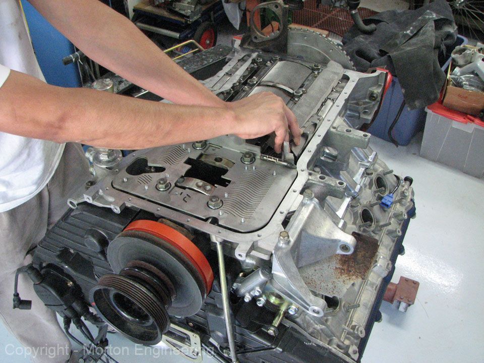
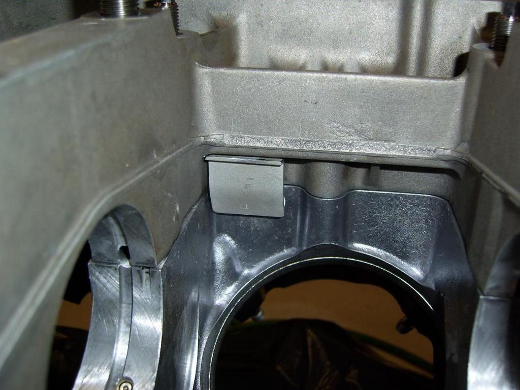
Manage the (mostly cyclical) gas flows within the crankcase. The modern four-valve V8 engines are usually designed with a girdle plate structure and a shallow oil pan that makes bay-to-bay breathing cumbersome and with a large cavity under the valve cover that is used to buffer and communicate the piston pumping pulses thru the head oil drain channels. The 928 S4 engine is a prime example. In my opinion, the cycle average flow rates are relatively unimportant compared to these pulsing flows (although of course one also wants to direct the average flow rates in a productive way by not evacuating the crankcase gas from the valve covers under full throttle). A pan spacer will help by providing a larger path for piston pumping pulses to communicate between bays thru the pan (instead of thru the valve cover cavities). The bay-to-bay breathing holes in the block main webs are ported to remove casting slack and to flow better. The I-J system has oil drain plates (picture of approximately equivalent plates below) that guide the draining oil away from the spinning crankshaft -- I am thinking that those plates are serving a function of blocking the piston pumping pulses from directly blowing into the heads.
The I-J drain passage blocking plates in the blue engine are similar to those used in the 928MS system:
Mike Simard's plates are more elegant than the above or the I-J plates in the blue engine:
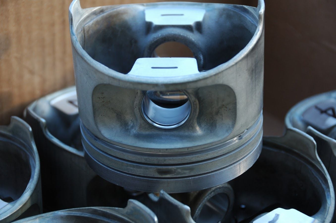
With these piston ring widths and the stock stroke, there's always going to be relatively low rpm at which the rings start fluttering. Longer stroke makes the ring flutter rpm even lower:
There's no way to make the stock piston's top ring groove narrower, so it is what it is.
The blue engine with turbos is going to hit multiple walls at about the same rpm level close to 7000 rpm: ring flutter, forces on the rod and rod bearings due to heavy piston assemblies, oil pressure required to supply the cross-drilled-mains crankshaft, piston pumping pulses in the crankcase, 90-degree exhaust blowdown interference and resulting knock, low valve spring loads, tuned lengths of the stock intake manifold, etc. The glass half empty way of looking at it is that it'll be expensive to take the 928 engine to higher rpms. The glass half full way of looking at it is that the design is well balanced with multiple constraints binding at about the same rpm that is well above what a turbo engine needs to make big power. I think the glass half full way to think about it is the right way! ;-)
Is there evidence of ring flutter in the 928 engine?
Evidence, yes. Absolute smoking gun proof, no.
The easiest way to collect some evidence is go on the dyno and load the car at various rpms. Then, observe the quantity of blowby gas (or gas and oil in the stock breather system) at various (high) rpms. If one is curious, one can vary some other operating conditions, for example by changing the oil level or by advancing/retarding ignition to cause/eliminate knock. If the oil level is low (and it can be low for short runs on a stationary dyno) and if there are no indications of detonation in the logs, then the rpm at which the blowby percentage increases dramatically is most likely the onset rpm of ring flutter.
Repeating this test procedure with the blue engine on a dyno with a blowby meter is on the list of things to do this January. (The previous engine was dynoed so much that the rear bumper cover partially melted in areas next to the exhaust pipe.)
Then these observations can be correlated with what we know about how the internal combustion engine works. For example, take a look at the (in my opinion very useful) linked document: http://www.grandprixengines.co.uk/note13.pdf , specifically "Note 13 Part II". If you use those empirical formulas and plug in the 928S4 parameters, you'll get a ring flutter critical rpm of 6530 [EDIT, that's probably a math error by me, the calculator says 6971 rpm.
Let's say the theory will match reality in this engine, are you planning to run it at/or over 6530 rpms?
The theoretical calculation assumes cast-iron ring density. It's also that we'll have much higher cylinder pressures helping to seat the rings than what was used to estimate those ring-flutter formulas. So it's not a divine prescription for those and many other reasons. (Especially since it now looks like I made an computational error when coming up with 6530, now the number is 6971...)
But to answer your hypothetical question: Let's say for arguments sake that we determine the ring flutter onset rpm to be 6750 rpm under boost, then most likely our decision is to limit the rpm to below that level.
As the linked document states:
Up to the early 50s piston acceleration -- or rather deceleration of the piston rings at the end of the exhaust stroke -- could form a limit to engine speed. This was because the ring momentum at the minimum producible rectangular-section (plain) ring axial width (and therefore minimum mass) could overcome the residual gas pressure so that the ring was thrown to the top of its groove. Gas pressure then could no longer reach the inside of the ring to compensate for that on the outside and the ring would be forced inwards. Apart from the resulting gas blow-by, losing power, degrading the oil and pushing it out of the engine, the ring radial vibration with RPM –“flutter” – would lead to very rapid fatigue failure of the cast-iron material then used. Over-revved engines would be found to have their rings broken into many pieces.
... For very short durations engines could be operated beyond the flutter boundary, e.g. the 1936 Austin 750cc listed in Note Ersatz 16 Part I was run up to 10,000 for Shelsley hill-climbs, a matter of only a few seconds at max. speed before the engine would be overhauled.
...It is possible that, with improved materials, the rings are allowed to flutter and can still survive for a life required of only 400km and that the really powerful sump-scavenging and de-aeration systems now used, with improved oil, still allow the lubricant to do a satisfactory job for the less-than-2 hours needed, despite blow-by. Cases are known in recent years where piston-ring-flutter has been acknowledged: in the 1989 Canadian GP, run in rain, the Honda V10 3.5L engine of a McLaren failed when leading because on-off use of the throttle to keep control on the slippery track led to ring flutter and blow-by which caused excessive oil loss; the 1994 Peugeot V10 3.5L engine, also in a McLaren, lost all of its 15L of oil at Monaco (727), almost certainly because of ring-flutter since, not long afterwards, a McLaren-Peugeot caught fire on the British GP grid and it was admitted that ring-flutter had forced oil loss onto the exhaust.
The easiest way to collect some evidence is go on the dyno and load the car at various rpms. Then, observe the quantity of blowby gas (or gas and oil in the stock breather system) at various (high) rpms. If one is curious, one can vary some other operating conditions, for example by changing the oil level or by advancing/retarding ignition to cause/eliminate knock. If the oil level is low (and it can be low for short runs on a stationary dyno) and if there are no indications of detonation in the logs, then the rpm at which the blowby percentage increases dramatically is most likely the onset rpm of ring flutter.
Repeating this test procedure with the blue engine on a dyno with a blowby meter is on the list of things to do this January. (The previous engine was dynoed so much that the rear bumper cover partially melted in areas next to the exhaust pipe.)
Then these observations can be correlated with what we know about how the internal combustion engine works. For example, take a look at the (in my opinion very useful) linked document: http://www.grandprixengines.co.uk/note13.pdf , specifically "Note 13 Part II". If you use those empirical formulas and plug in the 928S4 parameters, you'll get a ring flutter critical rpm of 6530.
Here is a simple calculator which needs just stroke, connection rod length and 1st compression ring thickness as input to estimate how high the engine may be revved with steady sealing. http://alfatune.fi/cms_naytasivu.php?sivu=100
For example a stroker 928 (3.750") having a .031" (0.8mm) top ring and 6.0" rods the critical ring flutter rpm will be calculated to 8522 rpm.
�ke

 01-01-2017, 03:04 PM