

Odometer Repair Procedure w/pics
 08-27-2009, 12:03 AM
#1
Three Wheelin'
Thread Starter
Join Date: Sep 2007
Location: Ridgecrest, California
Posts: 1,363
Likes: 0
Received 148 Likes
on
32 Posts
While I was driving California ('84) to Oregon a few weeks back, the Odometer stopped working about 150 miles into a 1500 mile trip. When I returned home, I bought the replacement gear and replaced the broken drive gear and put the Odometer back together. After driving the car about 1500 miles to OCIC, the odometer stopped working again. So I took it apart and inserted a washer to take up the slack between the odometer tumblers. I've put another 3000 miles on the car from Maryland back to California recently and the odometer is still going strong.
I took a couple of pictures (of course) and thought I'd share the procedure I followed with my fellow Newbies that want to make this repair. This repair applied to the '84 MY but should apply to most if not all the mechanical odometer MY.
Here's the tools I used to remove the pod:
13mm combination wrench
27mm socket, 6 inch extension, socket wrench
10mm socket
medium phillips
5mm allen socket (long)
Here's the tools I used to work on the instrument cluster/odometer:
medium phillips and small phillips screwdriver
flat blade screwdriver
7mm nut driver
standard pliers and needle nose pliers
small, thin wire
replacement odometer drive gear (available at www.rennbay.com/-c-32.html) for about $27.50.
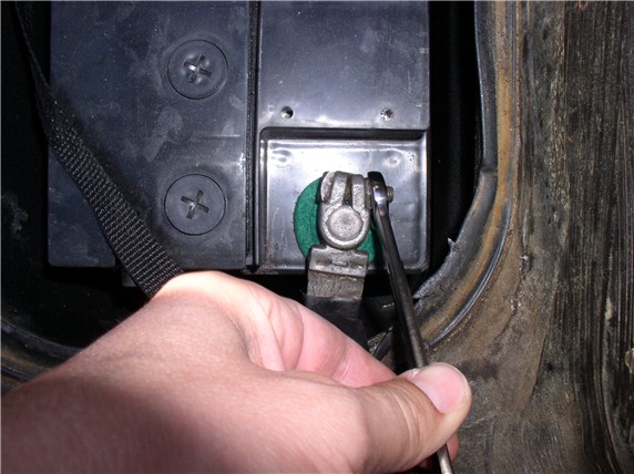
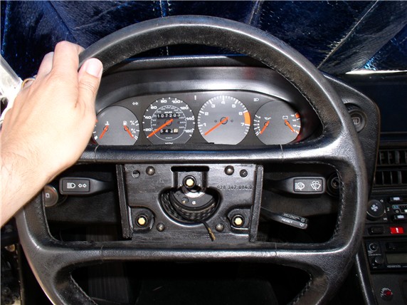
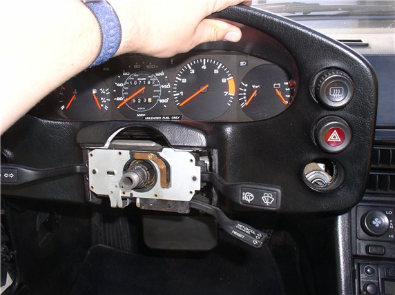
First you will need to remove the pod in order to remove the instrumentation cluster. In a previous post I included a procedure for fully disassembling the pod in order to remove it. However, in this procedure, we'll follow a shortcut to getting at the instrumentation cluster without fully disassembling and removing the pod making this procedure considerably easier. First, disconnect the negative battery terminal using the 13mm combo wrench.
Next, remove the horn pad by gripping it on both ends with your hands and giving if a firm tug toward you. There are 3 clips that hold the horn pad to the wheel (one on top-center and 2 on the bottom half (left and right)). Use "shallow" but firm tugs. There is a horn wire connected to the back of the pad and you don't want to violently pull the pad off the wheel and damage the wire/connector.
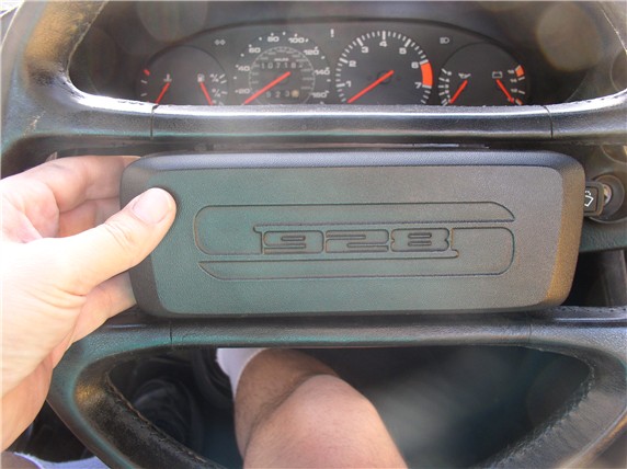
After the horn pad is off, disconnect the horn wire.
Next, use the 27mm socket and extension to loosen and remove the nut that secures the steering wheel to the steering column. I've had good luck simply holding the steering wheel firmly with my left hand while using my right to use the wrench. It's best to NOT use the steering wheel locking mechanism to hold the steering wheel in place while you loosen the nut - the force could damage the locking mechanism. If you can't hold the steering wheel with one hand, a helper may be able to hold the steering wheel in place while you loosen the nut. Do not remove the nut completely from the steering column threads. By leaving the nut on the column, it will act as a safety stop when you pull the steering wheel off the column and keep the steering wheel from hitting you in the face.
Before pulling the steering wheel off the steering column, center the steering wheel as perfectly as you can so you can easily orient the steering wheel in the same location when putting it back on. Then give the steering wheel a good firm tug toward you to remove it. When loose, take the nut off the column and remove the wheel.
Lower the tilt wheel paddle.
Then remove the two phillips screws that hold the underpod cover plate in place. There's one on the left, and.....
....one on the right.
The underpod cover plate is removed by sliding it toward the front of the car in order for the tab/prongs to clear. You can see the tabs indicated by the arrow in the picture below. These tabs can easily break off if forced down without pulling the plate forward.
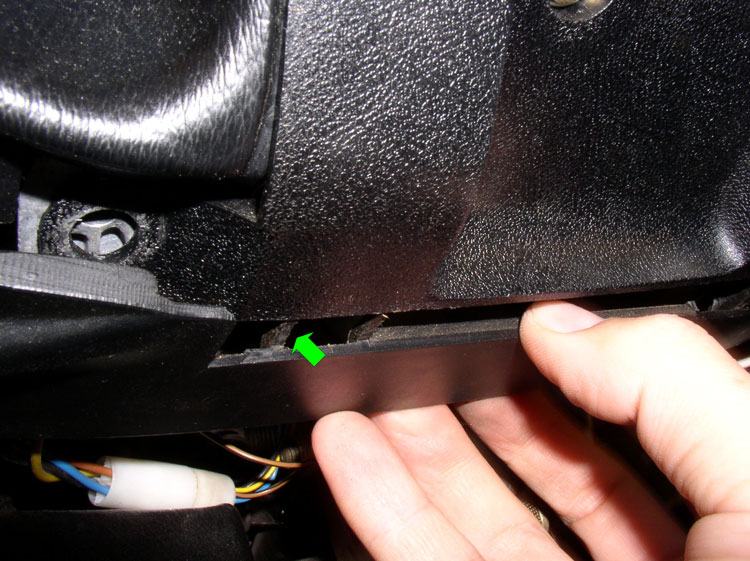
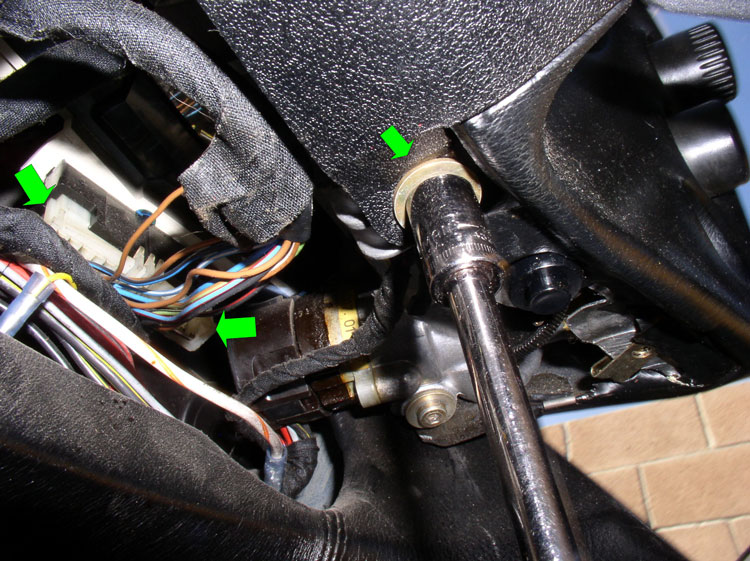
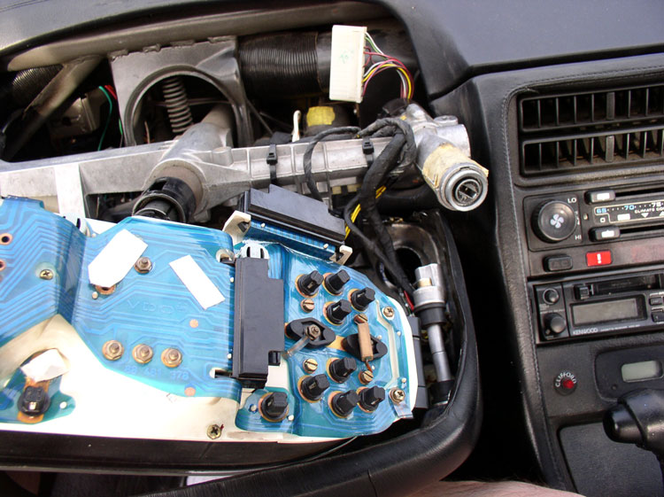
Next, remove the two 10mm bolts that secure the signal/wiper/cruise cluster cover as indicated by the great arrow. There's one bolt on the right and one on the left of the signal/wiper/cruise cluster. By now you may also notice the electrical harness connector to the instrumentation cluster underneath (indicated by the 2 green arrows). There should be a harness connection on the left and one on the right underneath the pod. We will disconnect these shortly.
Remove the phillips screw from the signal/wiper/cruise cluster cover and...
....remove the cover.
Continued.....
I took a couple of pictures (of course) and thought I'd share the procedure I followed with my fellow Newbies that want to make this repair. This repair applied to the '84 MY but should apply to most if not all the mechanical odometer MY.
Here's the tools I used to remove the pod:
13mm combination wrench
27mm socket, 6 inch extension, socket wrench
10mm socket
medium phillips
5mm allen socket (long)
Here's the tools I used to work on the instrument cluster/odometer:
medium phillips and small phillips screwdriver
flat blade screwdriver
7mm nut driver
standard pliers and needle nose pliers
small, thin wire
replacement odometer drive gear (available at www.rennbay.com/-c-32.html) for about $27.50.
First you will need to remove the pod in order to remove the instrumentation cluster. In a previous post I included a procedure for fully disassembling the pod in order to remove it. However, in this procedure, we'll follow a shortcut to getting at the instrumentation cluster without fully disassembling and removing the pod making this procedure considerably easier. First, disconnect the negative battery terminal using the 13mm combo wrench.
Next, remove the horn pad by gripping it on both ends with your hands and giving if a firm tug toward you. There are 3 clips that hold the horn pad to the wheel (one on top-center and 2 on the bottom half (left and right)). Use "shallow" but firm tugs. There is a horn wire connected to the back of the pad and you don't want to violently pull the pad off the wheel and damage the wire/connector.
After the horn pad is off, disconnect the horn wire.
Next, use the 27mm socket and extension to loosen and remove the nut that secures the steering wheel to the steering column. I've had good luck simply holding the steering wheel firmly with my left hand while using my right to use the wrench. It's best to NOT use the steering wheel locking mechanism to hold the steering wheel in place while you loosen the nut - the force could damage the locking mechanism. If you can't hold the steering wheel with one hand, a helper may be able to hold the steering wheel in place while you loosen the nut. Do not remove the nut completely from the steering column threads. By leaving the nut on the column, it will act as a safety stop when you pull the steering wheel off the column and keep the steering wheel from hitting you in the face.
Before pulling the steering wheel off the steering column, center the steering wheel as perfectly as you can so you can easily orient the steering wheel in the same location when putting it back on. Then give the steering wheel a good firm tug toward you to remove it. When loose, take the nut off the column and remove the wheel.
Lower the tilt wheel paddle.
Then remove the two phillips screws that hold the underpod cover plate in place. There's one on the left, and.....
....one on the right.
The underpod cover plate is removed by sliding it toward the front of the car in order for the tab/prongs to clear. You can see the tabs indicated by the arrow in the picture below. These tabs can easily break off if forced down without pulling the plate forward.
Next, remove the two 10mm bolts that secure the signal/wiper/cruise cluster cover as indicated by the great arrow. There's one bolt on the right and one on the left of the signal/wiper/cruise cluster. By now you may also notice the electrical harness connector to the instrumentation cluster underneath (indicated by the 2 green arrows). There should be a harness connection on the left and one on the right underneath the pod. We will disconnect these shortly.
Remove the phillips screw from the signal/wiper/cruise cluster cover and...
....remove the cover.
Continued.....
 08-27-2009, 01:26 AM
#2
Three Wheelin'
Thread Starter
Join Date: Sep 2007
Location: Ridgecrest, California
Posts: 1,363
Likes: 0
Received 148 Likes
on
32 Posts
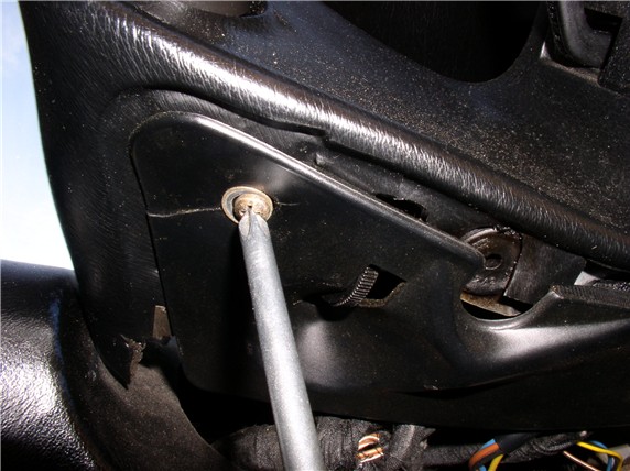
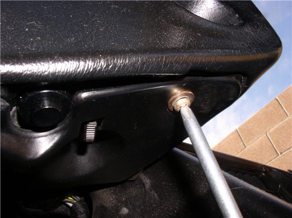
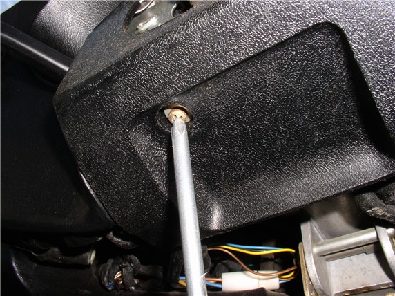
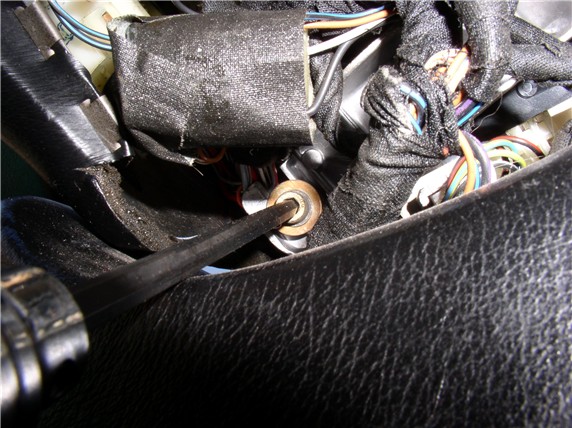
Next, remove the right allen head bolt that secures the pod to the dash framework. It's located to the right and underneath the pod (underneath the ignition switch module). I used a 5mm allen socket (long).
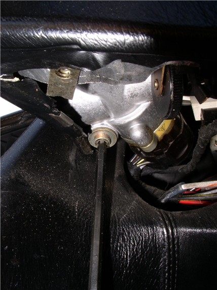
Remove the allen bolt on the left underneath the pod.
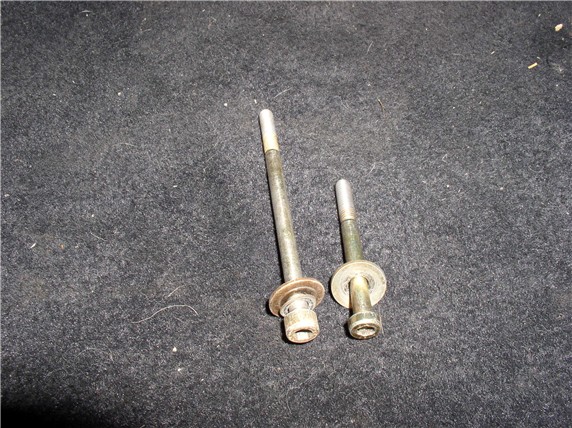
Note that the long bolt is used on the left side and the short bolt on the right.
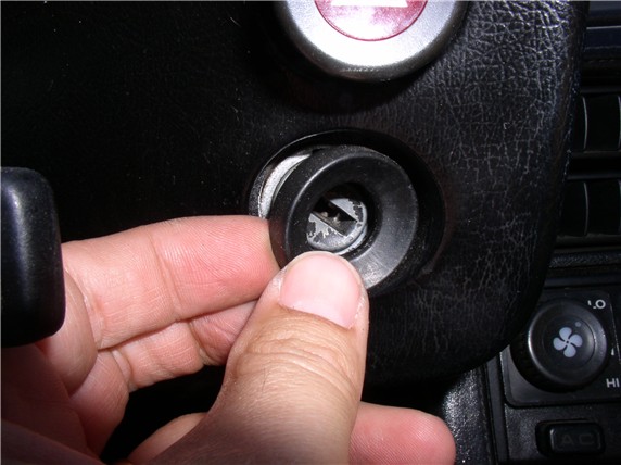
Remove the rubber gromet around the ignition switch. You can use a flat blade screwdriver to assist with the removal.
Next, we need to remove the signal/wiper/cruise cluster from the steering column. But first we need to manuever the pod so the cluster will clear. Start by pulling the pod forward enough to clear the ignition switch. Then lift the pod slightly - enough so the signal/wiper/cruise cluster will clear the pod.
While holding the pod up with one hand, use the other to grasp the signal/wiper/cuise cluster and twist while pulling toward you. Eventually, it will begin to work free and move toward you. I noticed on my cluster that there is a place for a clamping bolt to hold it in place on the steering column. However, no bolt was in place. If yours has a clamping bolt in place, you will need to loosen it in order to move the cluster. Move the cluster forward on the column enough so you can reach behind the cluster and disconnect the two wiring harnesses.
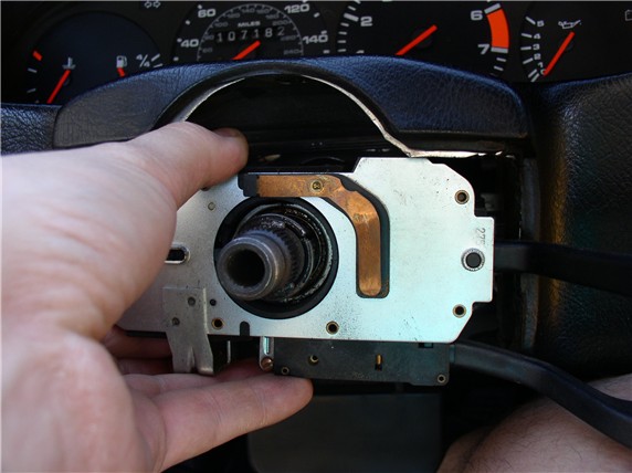
Once, you've detached the harness connectors, you will be able to remove the cluster from the steering column. The cruise wire connector (a small barrell connector) is still connected but you can leave that in place and let the cluster hang down.
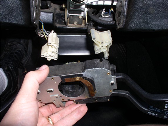
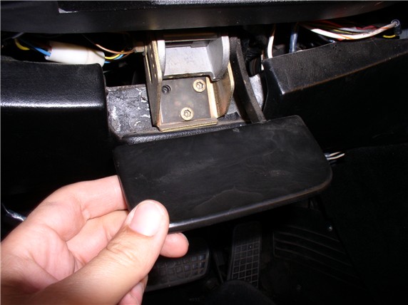
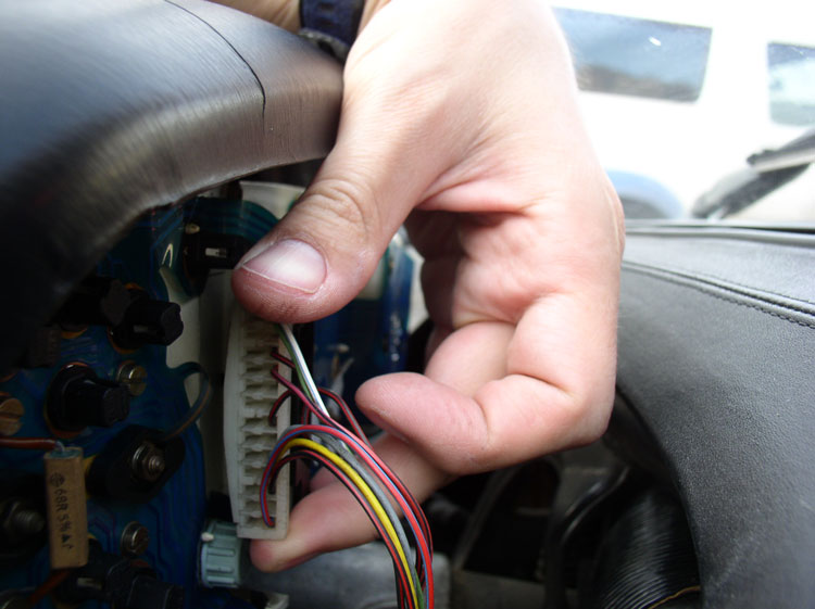
Next, disconnect the instrumentation cluster wiring harness leads from underneath the pod. These were pointed out earlier with the green arrows. There's a connector on the left of the pod and one on the right. Disconnect both of these by grasping the ends of the connector and rocking the connector side to side while pulling down. You can remember the orientation by the plastic locking clips (shown on top of the harness lead in the photo).
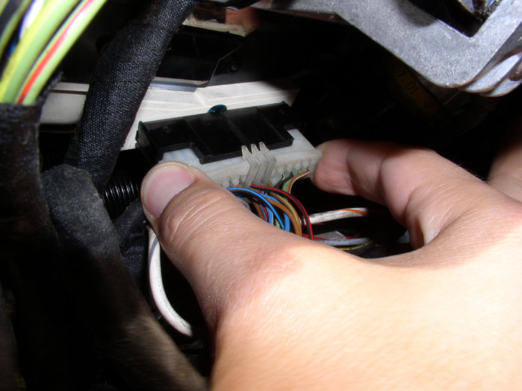
Then, move the pod slightly forward enough to get behind it and disconnect the third and final harness lead.
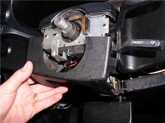
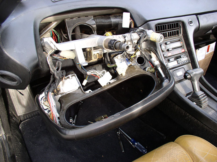
Pull the pod forward enough to just clear the end of the steering column...
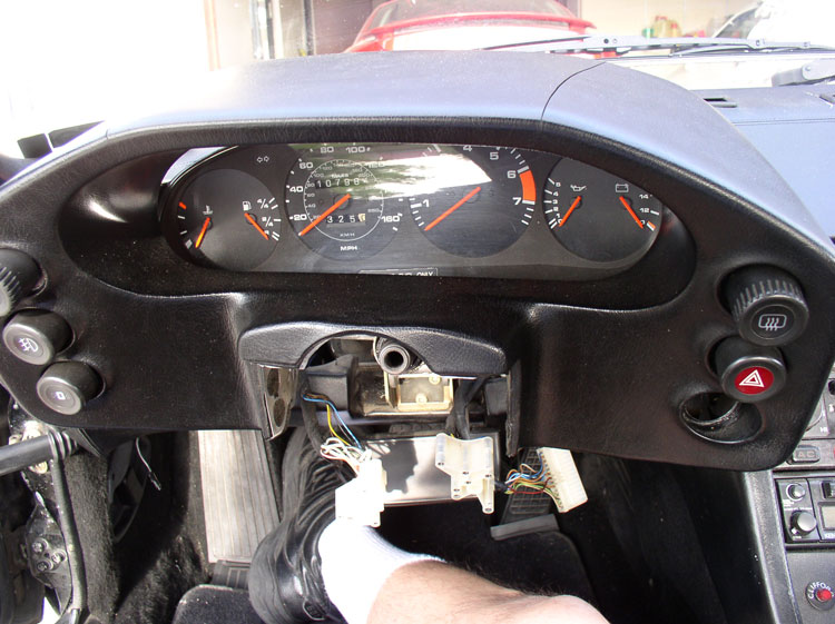
...and rotate the pod downward as shown in the picture.

Continue to rotate it downward until it is facedown in your lap.
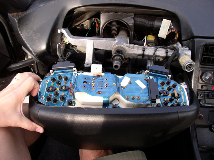
Now you are ready to remove the instrmentation cluster from the pod. The left side of the cluster should be free to move upward. Begin by lifting the left side of the cluster upward as shown in the picture. You will notice there are two aluminum/rubber bushings/guides for the securing allen head bolts attached to the end of the instrumentation cluster. You can leave these in or take them out and put them in a safe place (remember their orientation - rubber ends to the outsider).
Continued.....
Remove the allen bolt on the left underneath the pod.
Note that the long bolt is used on the left side and the short bolt on the right.
Remove the rubber gromet around the ignition switch. You can use a flat blade screwdriver to assist with the removal.
Next, we need to remove the signal/wiper/cruise cluster from the steering column. But first we need to manuever the pod so the cluster will clear. Start by pulling the pod forward enough to clear the ignition switch. Then lift the pod slightly - enough so the signal/wiper/cruise cluster will clear the pod.
While holding the pod up with one hand, use the other to grasp the signal/wiper/cuise cluster and twist while pulling toward you. Eventually, it will begin to work free and move toward you. I noticed on my cluster that there is a place for a clamping bolt to hold it in place on the steering column. However, no bolt was in place. If yours has a clamping bolt in place, you will need to loosen it in order to move the cluster. Move the cluster forward on the column enough so you can reach behind the cluster and disconnect the two wiring harnesses.
Once, you've detached the harness connectors, you will be able to remove the cluster from the steering column. The cruise wire connector (a small barrell connector) is still connected but you can leave that in place and let the cluster hang down.
Next, disconnect the instrumentation cluster wiring harness leads from underneath the pod. These were pointed out earlier with the green arrows. There's a connector on the left of the pod and one on the right. Disconnect both of these by grasping the ends of the connector and rocking the connector side to side while pulling down. You can remember the orientation by the plastic locking clips (shown on top of the harness lead in the photo).
Then, move the pod slightly forward enough to get behind it and disconnect the third and final harness lead.
Pull the pod forward enough to just clear the end of the steering column...
...and rotate the pod downward as shown in the picture.
Continue to rotate it downward until it is facedown in your lap.
Now you are ready to remove the instrmentation cluster from the pod. The left side of the cluster should be free to move upward. Begin by lifting the left side of the cluster upward as shown in the picture. You will notice there are two aluminum/rubber bushings/guides for the securing allen head bolts attached to the end of the instrumentation cluster. You can leave these in or take them out and put them in a safe place (remember their orientation - rubber ends to the outsider).
Continued.....
Last edited by Dwayne; 08-27-2009 at 10:28 AM.
The following users liked this post:
rdwalker (06-17-2024)
08-27-2009, 03:15 AM
#3
Under the Lift
Lifetime Rennlist
Member
Lifetime Rennlist
Member
Hi Dwayne:
This is a fun one. I replaced the gear in an 87 odo. Everything looked good, but the odo stopped working immediately. Went back in again and worked on the number wheel engagements, as they appeared jammed. Still didn't work. I'll be back in for the 3rd time tomorrow. Oh, well.
I'm sure this will end up as another one of your masterpieces. THANKS for documenting.
This is a fun one. I replaced the gear in an 87 odo. Everything looked good, but the odo stopped working immediately. Went back in again and worked on the number wheel engagements, as they appeared jammed. Still didn't work. I'll be back in for the 3rd time tomorrow.
Oh, well.I'm sure this will end up as another one of your masterpieces. THANKS for documenting.
08-27-2009, 07:15 AM
#4
Instructor
Join Date: Sep 2007
Location: NE PA aka-the endless mountains
Posts: 184
Likes: 0
Received 0 Likes
on
0 Posts
Yep. looks eerily familiar Dwayne. I did that a couple years back on my '84 and it worked out great. While I had it out I replaced all the bulbs. I also had some scratches on the clear front bezel that I rubbed out with a 3M plastic polish meant for such use. It really cleaned up nice.
Hope it works out as well for you.
Keith
Go Dwayne Go! Go Dwayne Go!
Hope it works out as well for you.
Keith
Go Dwayne Go! Go Dwayne Go!
Trending Topics
08-27-2009, 10:26 AM
#8
Three Wheelin'
Thread Starter
Join Date: Sep 2007
Location: Ridgecrest, California
Posts: 1,363
Likes: 0
Received 148 Likes
on
32 Posts
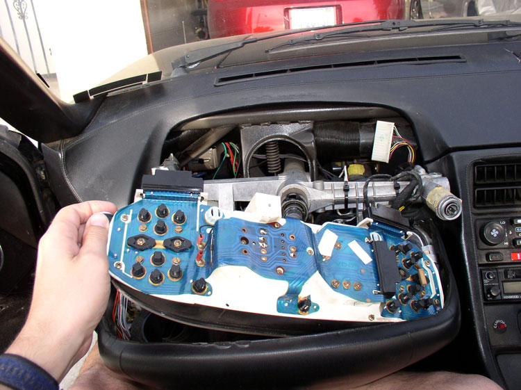
Next, you can simply pull the instument cluster to the right and away from the bushing/guides as pictured. You wil notice the right side bushing/guides are secured to the pod by another 5mm hex bolt. You can leave this in place as it will be easier to reassemble the cluster back into the pod.
You should now have the instrument cluster separated from the pod.
You can let the pod hang where it is or set it back up on the steering column.
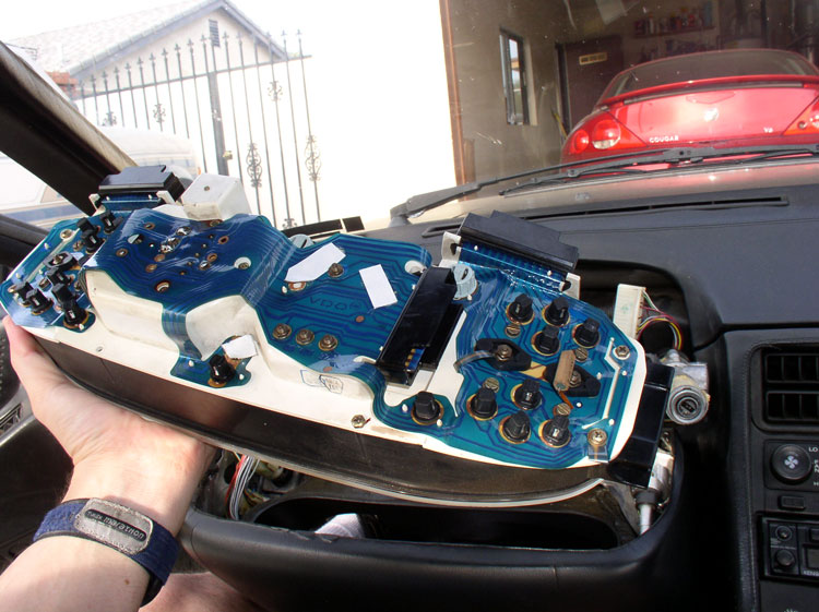
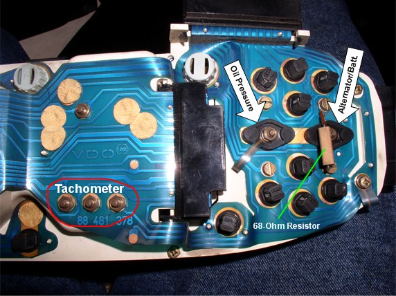
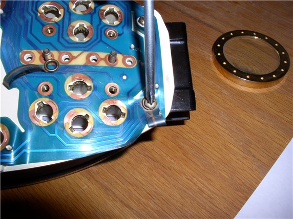
On the right side of the cluster you can see the contacts/securing nuts for the alternator guage, oil pressure guage and tachometer as pictured.
On the left side, you can see the temperature guage, fuel guage, odometer reset contacts, speedometer pulse signal, power, and ground contacts. I had to clean and solder the speedometer contacts last summer when my speedometer quit working.
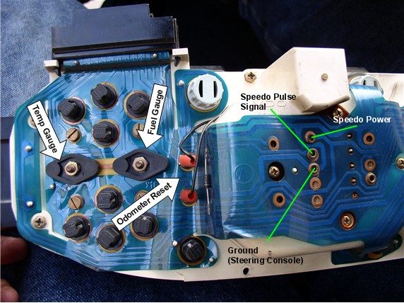
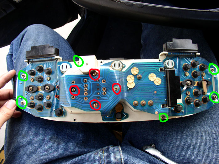
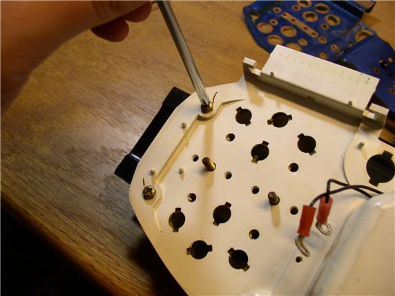
At this point, you have a couple of choices to proceed depending on your situation. If your only objective is to repair the odometer, you can take a shortcut to remove the speedo/odo unit only. If you have some cleaning to do on the instrument contacts etc., you can remove the printed plastic circut board from the instrument cluster to clean/solder and then remove the speedo/odo unit. I've included both options in this post. First, the shortcut. In order to remove the speedo/odo unit, you will remove the plastic front cover of the instrument cluster since the speedo/odo unit must be removed from the front. You will remove the phillips screws circled in green in the picture below. I only had 6 of the screws to remove. Your cluster may have more.
Second, the spedo/odo unit is secured using 4 small phillips screws circled in red in the picture below. remove these 4 screws using the small phillips screwdriver. Then, turn the cluster over with guages facing up and pull the plastic face cover off. Then, pull the speedo/odo unit upward, rocking gently side to side while pulling up. Then jump to post #13 of this thread to continue on with the repair procedure.
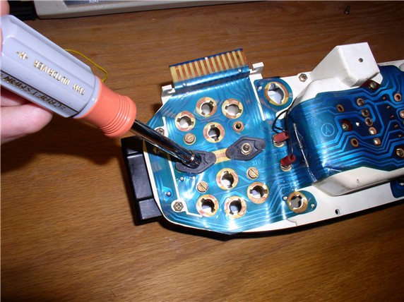
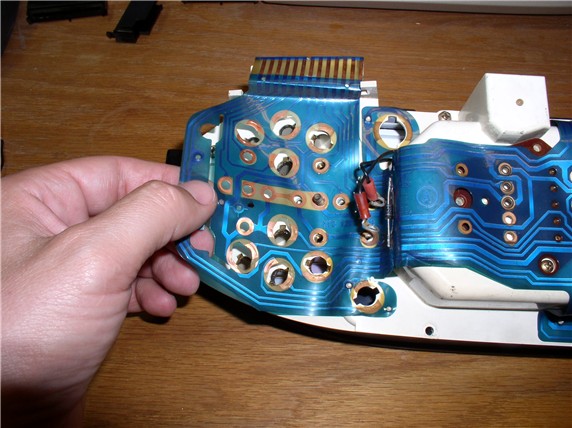
If you want to remove the plastic circuit board follow these steps. Remove all the small warning lights. These rotate 90 degrees counterclockwise then pull up and out.
Then, remove the larger 3 instrument board lights. These also rotate 90 degrees counterclockwise and pull up and out.
Next, useing the flat blade screwdriver, remove the guage contact screws. There are 2 per guage for a total of 8.
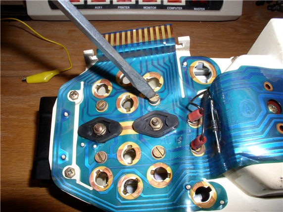
You will notice a 68 ohm resistor on the contact screws for the alternator guage. Remove this as well when you take the screws out.
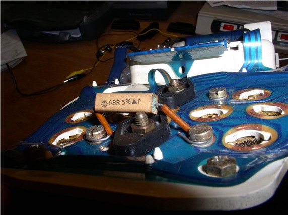
Next, using the 7mm nut driver, remove the center nut at the back of each guage as pictured.
You can then pull up on the plastic plug fitting using a pair of pliers as shown.
Continued......
You should now have the instrument cluster separated from the pod.
You can let the pod hang where it is or set it back up on the steering column.
On the right side of the cluster you can see the contacts/securing nuts for the alternator guage, oil pressure guage and tachometer as pictured.
On the left side, you can see the temperature guage, fuel guage, odometer reset contacts, speedometer pulse signal, power, and ground contacts. I had to clean and solder the speedometer contacts last summer when my speedometer quit working.
At this point, you have a couple of choices to proceed depending on your situation. If your only objective is to repair the odometer, you can take a shortcut to remove the speedo/odo unit only. If you have some cleaning to do on the instrument contacts etc., you can remove the printed plastic circut board from the instrument cluster to clean/solder and then remove the speedo/odo unit. I've included both options in this post. First, the shortcut. In order to remove the speedo/odo unit, you will remove the plastic front cover of the instrument cluster since the speedo/odo unit must be removed from the front. You will remove the phillips screws circled in green in the picture below. I only had 6 of the screws to remove. Your cluster may have more.
Second, the spedo/odo unit is secured using 4 small phillips screws circled in red in the picture below. remove these 4 screws using the small phillips screwdriver. Then, turn the cluster over with guages facing up and pull the plastic face cover off. Then, pull the speedo/odo unit upward, rocking gently side to side while pulling up. Then jump to post #13 of this thread to continue on with the repair procedure.
If you want to remove the plastic circuit board follow these steps. Remove all the small warning lights. These rotate 90 degrees counterclockwise then pull up and out.
Then, remove the larger 3 instrument board lights. These also rotate 90 degrees counterclockwise and pull up and out.
Next, useing the flat blade screwdriver, remove the guage contact screws. There are 2 per guage for a total of 8.
You will notice a 68 ohm resistor on the contact screws for the alternator guage. Remove this as well when you take the screws out.
Next, using the 7mm nut driver, remove the center nut at the back of each guage as pictured.
You can then pull up on the plastic plug fitting using a pair of pliers as shown.
Continued......
Last edited by Dwayne; 08-28-2009 at 09:59 AM.
08-27-2009, 11:59 AM
#9
Rennlist Member
Join Date: Nov 2008
Location: Park Hills, KY
Posts: 807
Likes: 0
Received 0 Likes
on
0 Posts
thanks Dwayne, your pics/procedure are much more clear than the WSM.
question, I have also read something about the elec motor that drives the ODO. since acquiring my 84 last year, the ODO started working again then stopped again. so in a addion to replacing the ODO gear, are you finding this a suggested replacement item WYAIT?
looking forward to the conclusion, this one is a keeper. add to my list of winter project.
08-27-2009, 01:26 PM
#10
Official Bay Area Patriot
Fuse 24 Assassin
Rennlist Member
Fuse 24 Assassin
Rennlist Member
http://www.klaindustries.net/gearinstr/gear-instr.htm
This link is for those who want to read ahead and get a general idea of the actual odometer gear replacement with the cluster apart. Note it says for 944, but the 928 cluster is virtually identical up until 1989.
Also if I remember when I did mine, you don't have to remove all the bulbs, just the senders when separating.
08-27-2009, 10:52 PM
#12
Three Wheelin'
Thread Starter
Join Date: Sep 2007
Location: Ridgecrest, California
Posts: 1,363
Likes: 0
Received 148 Likes
on
32 Posts
Next, use the 7mm nut driver to remove the contact nuts for the tachometer as shown.
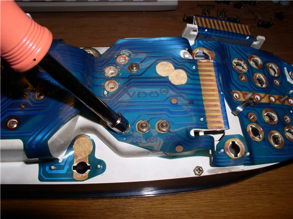
Then, remove the two phillips screws that secure the odometer reset wires.
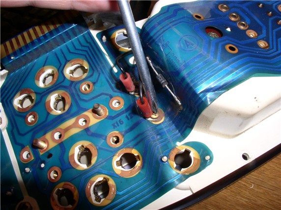
Next, you can remove the two phillips screws that secure the speedo hard circuit card to the instrument housing. One here as shown...
and the other one here.
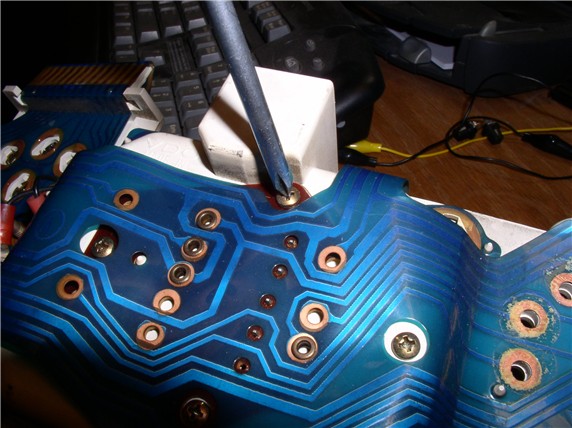
There is also one phillips screw securing the printed plastic circuit board to the instrument housing. Remove that screw as well.
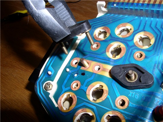
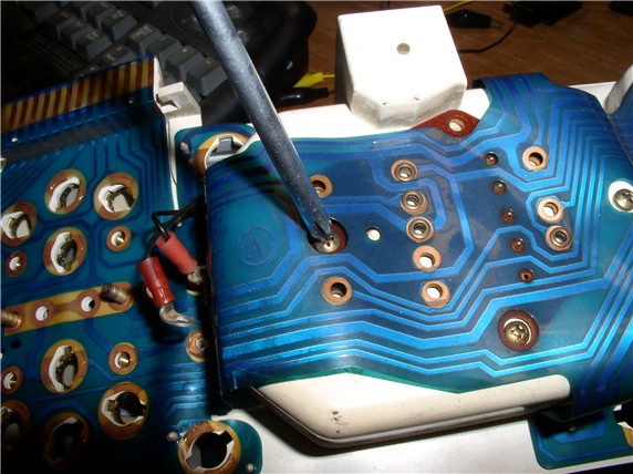
At this point, the printed plastic circuit board can be removed for cleaning or additional inspection. Start at one end and gently pull the printed plastic material up around the small plastic locating posts that hold it in place.
When you get to the speedo/odo unit (the hard circuit card), you can gently pry the hard card up with a flat blade screwdriver as shown.
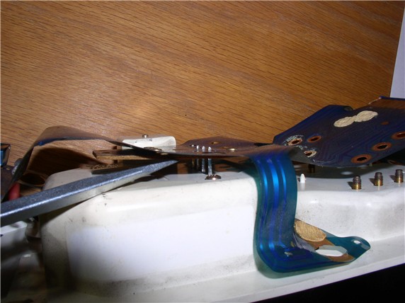
Continue removing the plastic material from the locating posts and the plastic circuit board will be removed. You can work on it separately, if needed.
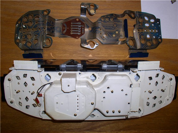
To continue on with removing the speedo/odo unit, remove the phillips screws that secure the instrument cluster face plate to the instrument housing.
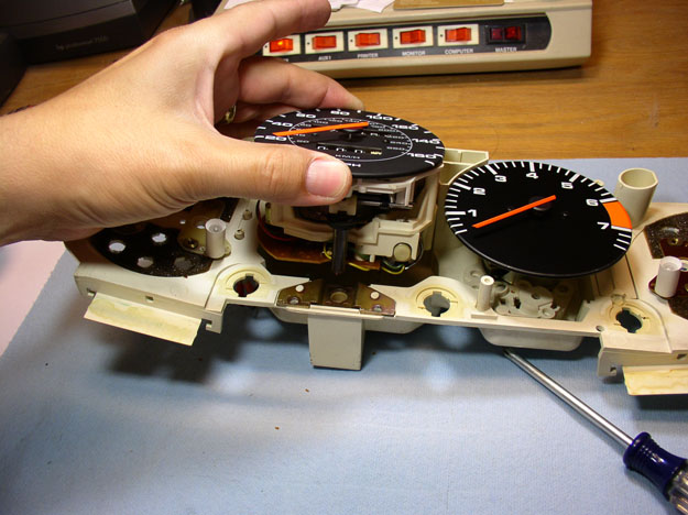
After removing all of the face plate screws, turn the instrument cluster over so gauges are facing up and lift off the face plate. The gauges should be exposed as shown.
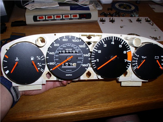
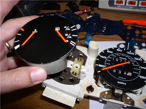
You should be able to remove the temp/fuel guage and the alternator/oil pressure guage by simply lifting up on them as shown. You can inspect/clean/repair these, if needed.
Now turn the instrument cluster on the side as shown and remove the two small phillips screws that secure the speedo/odo unit to the instrument housing.
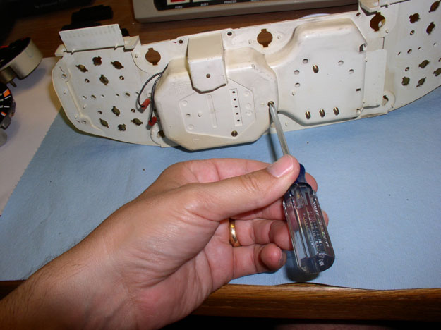
Second screw.
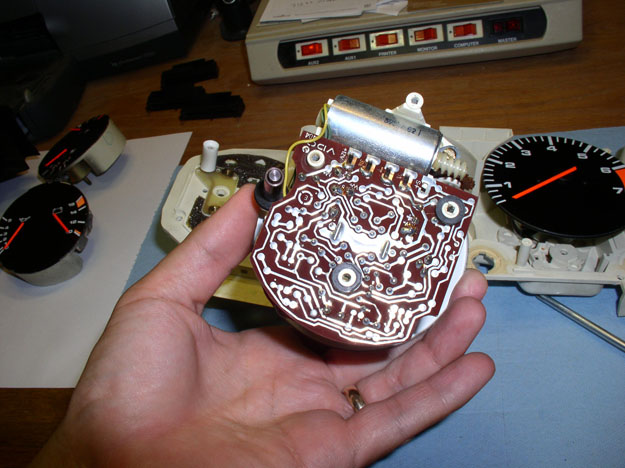
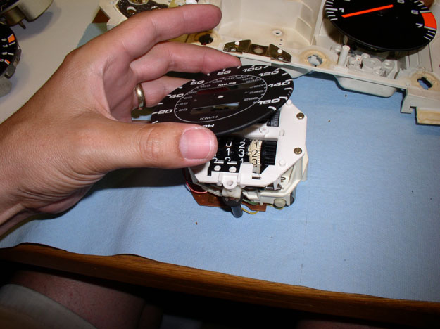
After the screws are removed, you can carefully lift up/pull out the speedo/odo unit as shown.
Inspect the unit for any obvious issues/damage. This inspection will also give you an idea what it should look like when you put it back in.
Continued.....
Then, remove the two phillips screws that secure the odometer reset wires.
Next, you can remove the two phillips screws that secure the speedo hard circuit card to the instrument housing. One here as shown...
and the other one here.
There is also one phillips screw securing the printed plastic circuit board to the instrument housing. Remove that screw as well.
At this point, the printed plastic circuit board can be removed for cleaning or additional inspection. Start at one end and gently pull the printed plastic material up around the small plastic locating posts that hold it in place.
When you get to the speedo/odo unit (the hard circuit card), you can gently pry the hard card up with a flat blade screwdriver as shown.
Continue removing the plastic material from the locating posts and the plastic circuit board will be removed. You can work on it separately, if needed.
To continue on with removing the speedo/odo unit, remove the phillips screws that secure the instrument cluster face plate to the instrument housing.
After removing all of the face plate screws, turn the instrument cluster over so gauges are facing up and lift off the face plate. The gauges should be exposed as shown.
You should be able to remove the temp/fuel guage and the alternator/oil pressure guage by simply lifting up on them as shown. You can inspect/clean/repair these, if needed.
Now turn the instrument cluster on the side as shown and remove the two small phillips screws that secure the speedo/odo unit to the instrument housing.
Second screw.
After the screws are removed, you can carefully lift up/pull out the speedo/odo unit as shown.
Inspect the unit for any obvious issues/damage. This inspection will also give you an idea what it should look like when you put it back in.
Continued.....
08-27-2009, 11:32 PM
#13
Three Wheelin'
Thread Starter
Join Date: Sep 2007
Location: Ridgecrest, California
Posts: 1,363
Likes: 0
Received 148 Likes
on
32 Posts
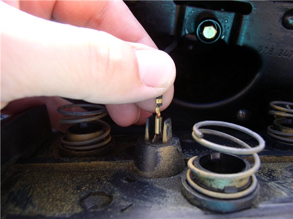
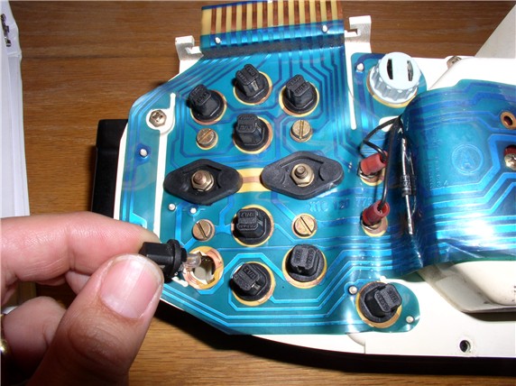
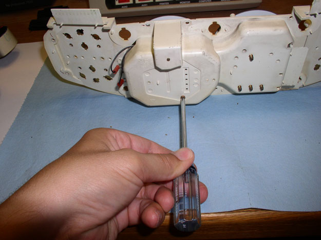
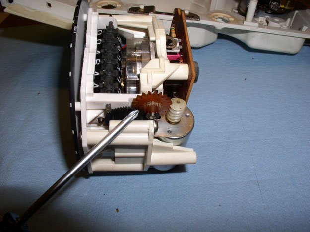
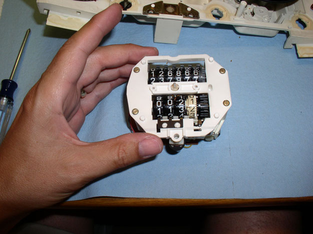
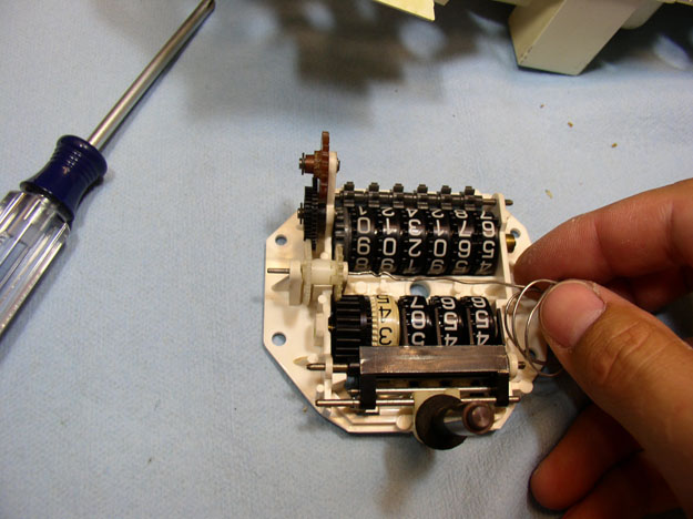
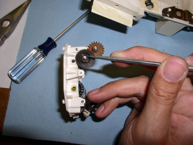
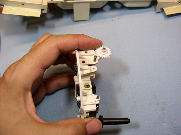
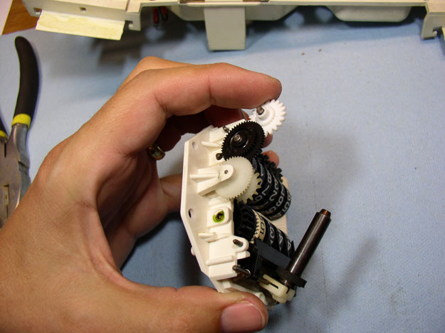
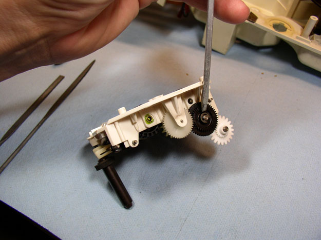
The odometer reset works on an electro magnet mechanism. You can pull down on the cylinder as shown and it will manually reset the odometer.
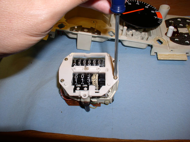
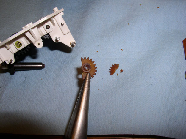
The odometer gear pointed at by the screwdriver is the one that failed. The gear has a set of outer teeth that interlock with the worm gear of the drive motor as shown. The inner teeth, interlock with the next gear wheel. Because the first gear is prone to becoming brittle with age, when it encounters resistance (such as the odometer tumblers locking due to excessive gap between the tumblers), it can strip the inner gear teeth off. Such as the case with mine.
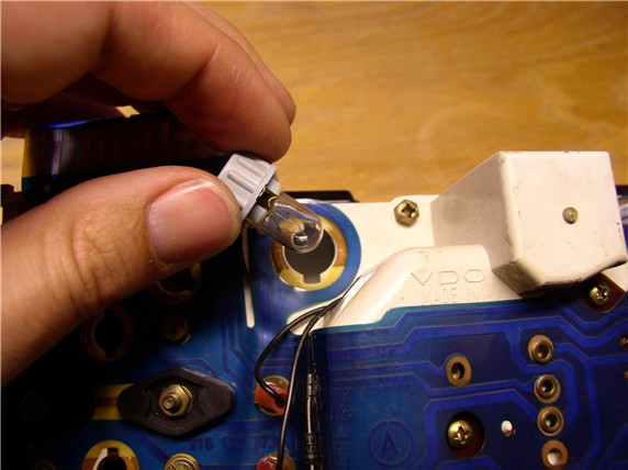
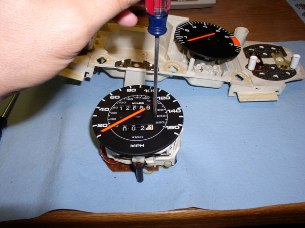
In order to replace the failed gear, I disassembled the speedo/odo unit. First, you'll need to remove the face plate in order to get at the housing screws. Before removing the face plate and needle, make special note of where the speedometer needle is oriented on the face plate. At rest, my needle lined up directly over the first line/mark of the speedometer facing. You'll want to re-install the needle later in the exact same position. You can remove the two small face plate screws as shown.
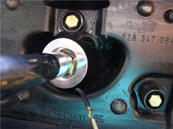
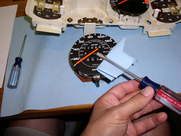
You'll need to remove the needle in order to remove the face plate. The speedo needle is press fitted on a small spindle with fine gear teeth on the end. It needs to be pried off carefully. You can use a flat blade screwdriver for this. Make sure you place a cloth or towel under the screwdriver to protect the finish on the speedo face plate. I applied a constant force with the screwdriver with one hand while grasping the black center plastic needle hub with the other hand and gently rocked it back and forth until it began to move free. Do not try to lift up the needle by the orange part. It is very easily bent.
Once the needle is free, remove it and set it aside.
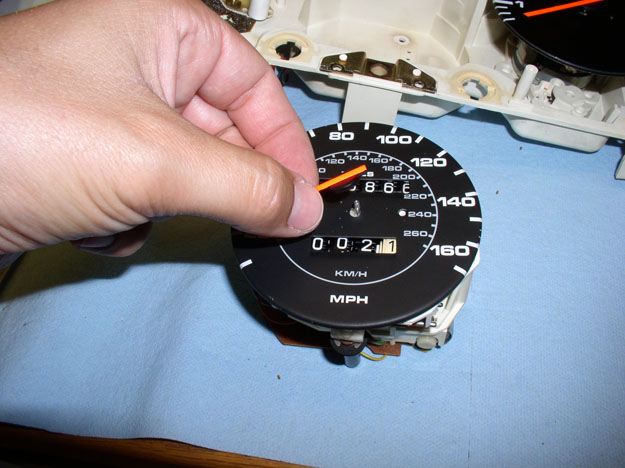
Now the face plate will come off as shown.
There are 4 small flat blade screws that hold the two halves of the unit together.
Remove the 4 screws in order to separate the mechanical half with tumblers from the electronics half.
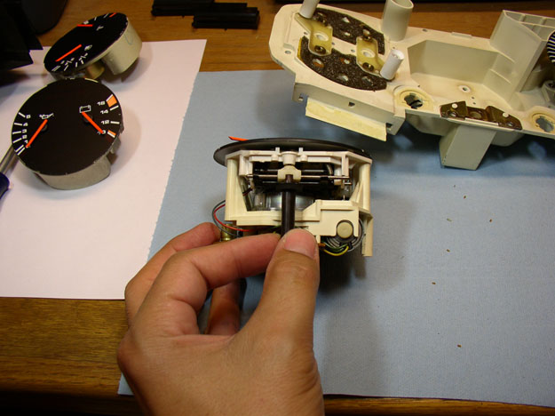
After the screws are removed, carefully separate the two halves by lifting up on the odo tumblers section as shown.
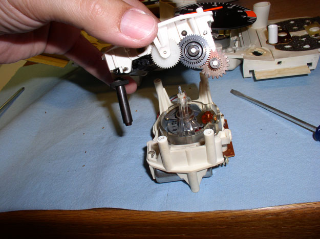
I needed to remove two gears in order to get at the failed gear. To remove the drum gear, I used a small thin wire to "push out" the gear pin holding the gear in place.
Once the gear pin is partially out, grasp it with some needle nose pliers...
...and remove it. Set is aside on a clean paper towel or other organized parts collection area.
After the pin is removed, you can grasp the drum gear with the needle nose pliers as shown and remove.
Continued....
The odometer gear pointed at by the screwdriver is the one that failed. The gear has a set of outer teeth that interlock with the worm gear of the drive motor as shown. The inner teeth, interlock with the next gear wheel. Because the first gear is prone to becoming brittle with age, when it encounters resistance (such as the odometer tumblers locking due to excessive gap between the tumblers), it can strip the inner gear teeth off. Such as the case with mine.
In order to replace the failed gear, I disassembled the speedo/odo unit. First, you'll need to remove the face plate in order to get at the housing screws. Before removing the face plate and needle, make special note of where the speedometer needle is oriented on the face plate. At rest, my needle lined up directly over the first line/mark of the speedometer facing. You'll want to re-install the needle later in the exact same position. You can remove the two small face plate screws as shown.
You'll need to remove the needle in order to remove the face plate. The speedo needle is press fitted on a small spindle with fine gear teeth on the end. It needs to be pried off carefully. You can use a flat blade screwdriver for this. Make sure you place a cloth or towel under the screwdriver to protect the finish on the speedo face plate. I applied a constant force with the screwdriver with one hand while grasping the black center plastic needle hub with the other hand and gently rocked it back and forth until it began to move free. Do not try to lift up the needle by the orange part. It is very easily bent.
Once the needle is free, remove it and set it aside.
Now the face plate will come off as shown.
There are 4 small flat blade screws that hold the two halves of the unit together.
Remove the 4 screws in order to separate the mechanical half with tumblers from the electronics half.
After the screws are removed, carefully separate the two halves by lifting up on the odo tumblers section as shown.
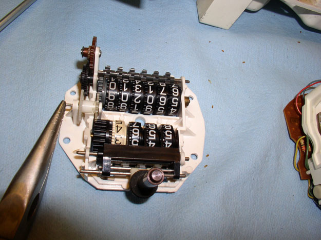
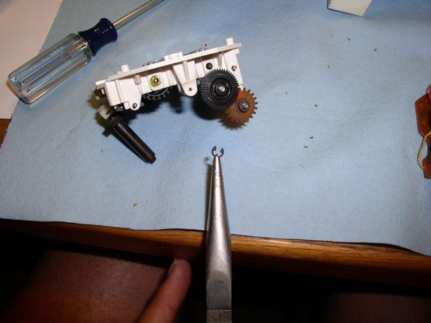
I needed to remove two gears in order to get at the failed gear. To remove the drum gear, I used a small thin wire to "push out" the gear pin holding the gear in place.
Once the gear pin is partially out, grasp it with some needle nose pliers...
...and remove it. Set is aside on a clean paper towel or other organized parts collection area.
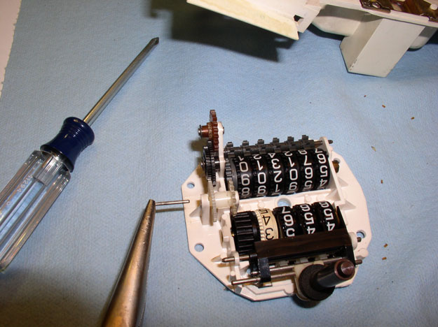
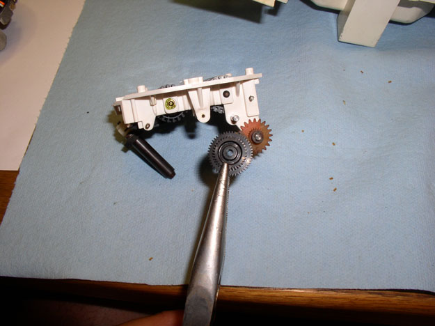
After the pin is removed, you can grasp the drum gear with the needle nose pliers as shown and remove.
Continued....
Last edited by Dwayne; 08-28-2009 at 10:05 AM.
08-28-2009, 12:13 AM
#14
Three Wheelin'
Thread Starter
Join Date: Sep 2007
Location: Ridgecrest, California
Posts: 1,363
Likes: 0
Received 148 Likes
on
32 Posts
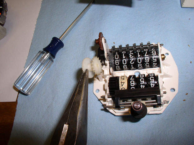
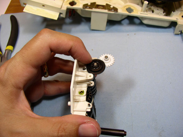
Next, you will need to remove the black intermediate gear. This gear and the first gear are held in place by a very small circlip. I used a small flat blad screwdriver to pry off the clip. Be very careful when prying the clip off as it can fly off and get lost. To prevent loss of the clip, I cupped my hand over the gear while prying.
Here's a pic of the clip when removed.
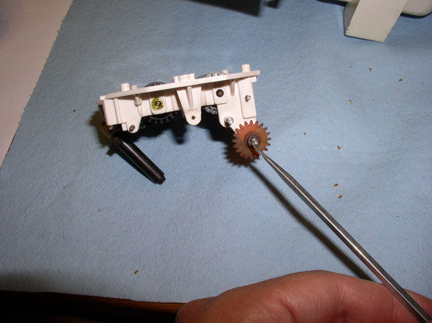
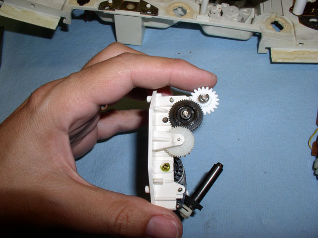
After the clip is removed, you can remove the black intermediate gear as shown.
Next, remove the circlip from the first gear wheel in the same manner as the intermediate gear.
Then remove the gear. Unfortunately, my gear was so brittle, it broke while I was removing the clip.
Here's the old gear compared to the new (white) gear I purchased from Rennbay.
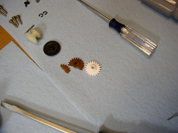
The new gear had some plastic "flash" left over from the molding process on one of the outer gear teeth. Use a small file to file down/remove any flash or rough edges left over from the molding process.
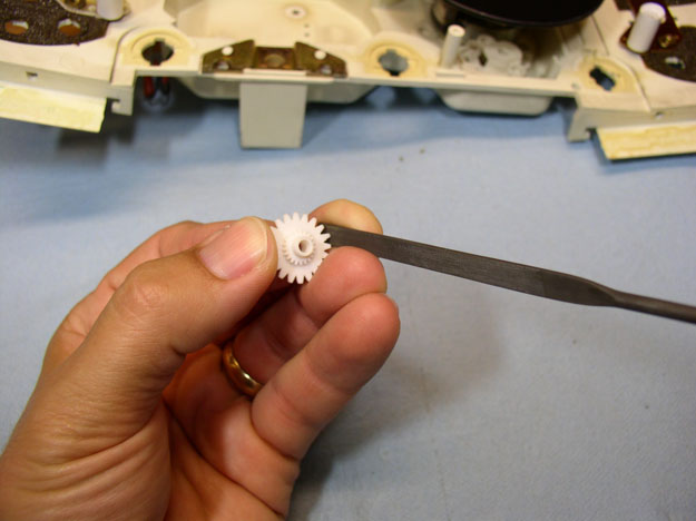
The new gear also had 3 small raised "knots" on the flat surface that mated with the intermediate gear. I assume these were also remnants from the moulding process. It is very important these protrusions be filed down level with the flat surface of the gear. If not, they will catch on the intermediate gear and hang (i.e., stop the odometer from working again).
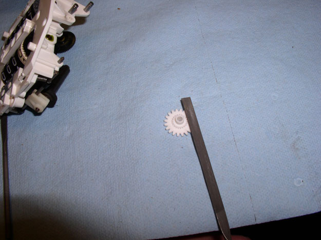
Once you are satisfied all surfaces are flat and smooth, place the gear on the odometer and spin with your finger checking for smooth operation. Now is an excellent time to also look for and clean any debris remaining from the old torn up gear. If there are small pieces of debris from the old gear falling apart left in the odometer tumblers or any of the gears, they can lock up the odometer. Inspect all gears, housing and tumblers for old gear debris while re-assembling the unit. We'll be inspecting the tumblers later when we remove them.
Next, set the black intermediate gear in place and again check for smooth operation. It took me two or three attempts at filing the "knots" off in order to get it perfectly smooth enough to pass this test.
Then, you can insert the drum gear as shown.....
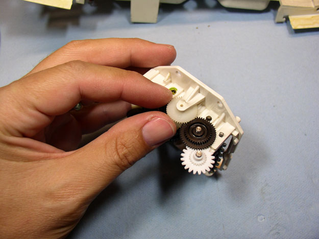
....and insert the drum gear pin as pictured below.
Now, check again for smooth operation. At this point, the odo tumblers should move as well.
Re-install the small circlips on the intermediate gear and the first gear.
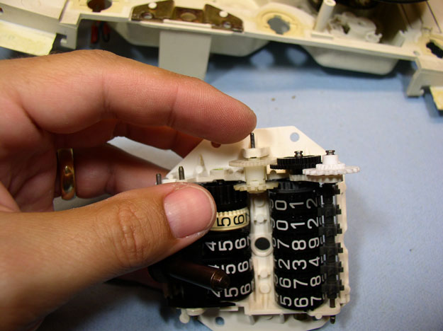
And check again for smooth operation. It was at this point I noticed that there was significant gap between my odo tumblers and if two tumblers were pushed apart, the gap was sufficient to "lock up" the odometer and prevent it from moving. The total gap between my tumblers appeared to be just under 1mm. Therefore, I would guess that if the total gap is more than 0.5mm, it is probably enough to cause the odometer to lock up under the right conditions. We'll look at removing the "gap" in the next set of steps.
Continued.....
Here's a pic of the clip when removed.
After the clip is removed, you can remove the black intermediate gear as shown.
Next, remove the circlip from the first gear wheel in the same manner as the intermediate gear.
Then remove the gear. Unfortunately, my gear was so brittle, it broke while I was removing the clip.
Here's the old gear compared to the new (white) gear I purchased from Rennbay.
The new gear had some plastic "flash" left over from the molding process on one of the outer gear teeth. Use a small file to file down/remove any flash or rough edges left over from the molding process.
The new gear also had 3 small raised "knots" on the flat surface that mated with the intermediate gear. I assume these were also remnants from the moulding process. It is very important these protrusions be filed down level with the flat surface of the gear. If not, they will catch on the intermediate gear and hang (i.e., stop the odometer from working again).
Once you are satisfied all surfaces are flat and smooth, place the gear on the odometer and spin with your finger checking for smooth operation. Now is an excellent time to also look for and clean any debris remaining from the old torn up gear. If there are small pieces of debris from the old gear falling apart left in the odometer tumblers or any of the gears, they can lock up the odometer. Inspect all gears, housing and tumblers for old gear debris while re-assembling the unit. We'll be inspecting the tumblers later when we remove them.
Next, set the black intermediate gear in place and again check for smooth operation. It took me two or three attempts at filing the "knots" off in order to get it perfectly smooth enough to pass this test.
Then, you can insert the drum gear as shown.....
....and insert the drum gear pin as pictured below.
Now, check again for smooth operation. At this point, the odo tumblers should move as well.
Re-install the small circlips on the intermediate gear and the first gear.
And check again for smooth operation. It was at this point I noticed that there was significant gap between my odo tumblers and if two tumblers were pushed apart, the gap was sufficient to "lock up" the odometer and prevent it from moving. The total gap between my tumblers appeared to be just under 1mm. Therefore, I would guess that if the total gap is more than 0.5mm, it is probably enough to cause the odometer to lock up under the right conditions. We'll look at removing the "gap" in the next set of steps.
Continued.....
Last edited by Dwayne; 08-29-2009 at 01:49 AM.
