

Odometer Repair Procedure w/pics
 08-28-2009, 01:22 AM
#16
Three Wheelin'
Thread Starter
Join Date: Sep 2007
Location: Ridgecrest, California
Posts: 1,363
Likes: 0
Received 149 Likes
on
33 Posts
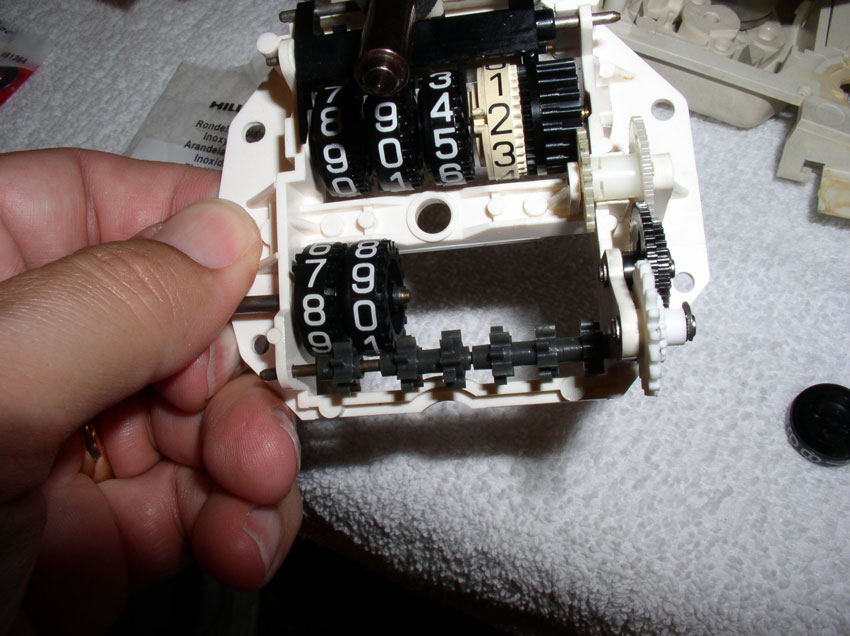
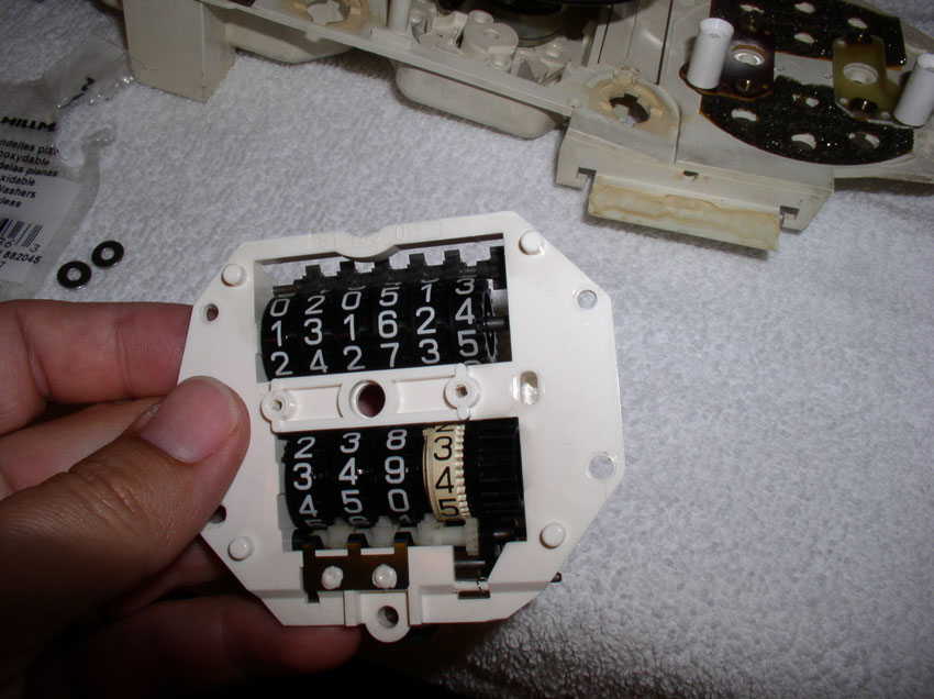
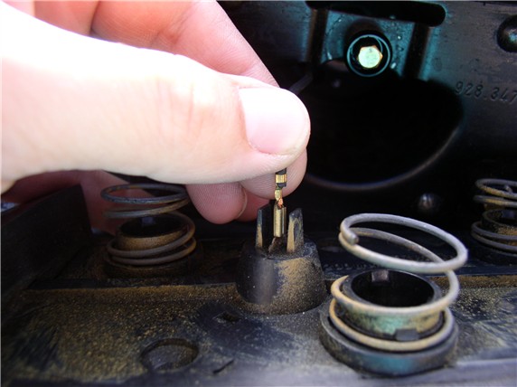
In these next steps, we'll be taking out the odo tumblers to insert a small washer to take out the gap/slack between the tumblers. This is also an excellent time to correct/add any missing miles that resulted from the car being driven with the odometer not working. Fortunately, I had a good idea of exactly how many miles were missing due to the failed odometer. First, we need to remove the tumblers. Grasp the tumbler shaft/pin by the end and pull outward as shown.
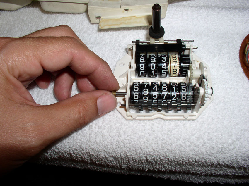
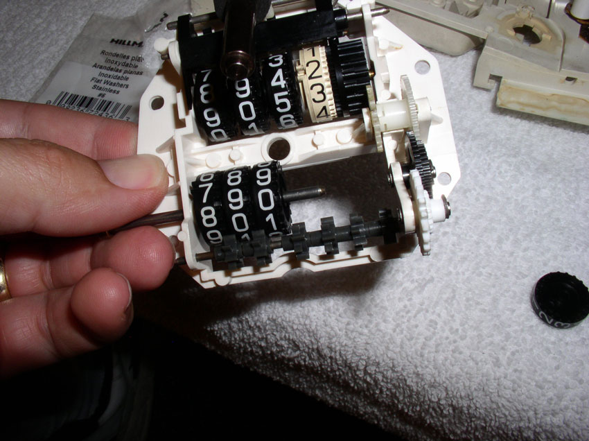
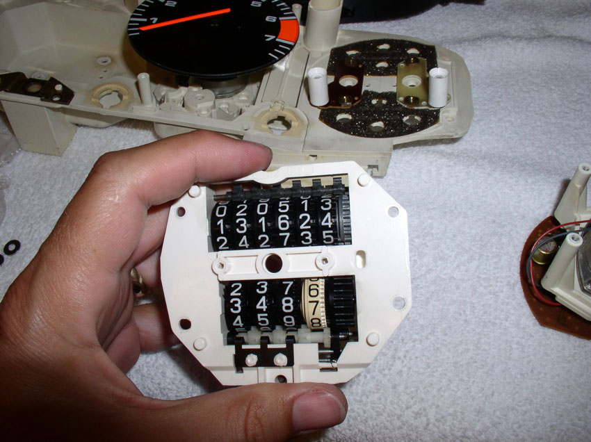
Fully remove the shaft/pin while the tumblers are face down on the table as shown.

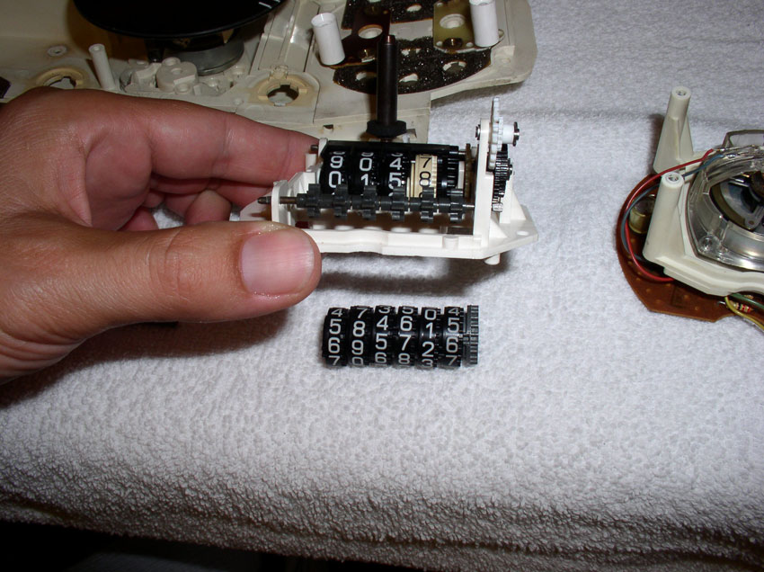
Then lift the odometer assembly and the tumblers should remain on the table as shown.
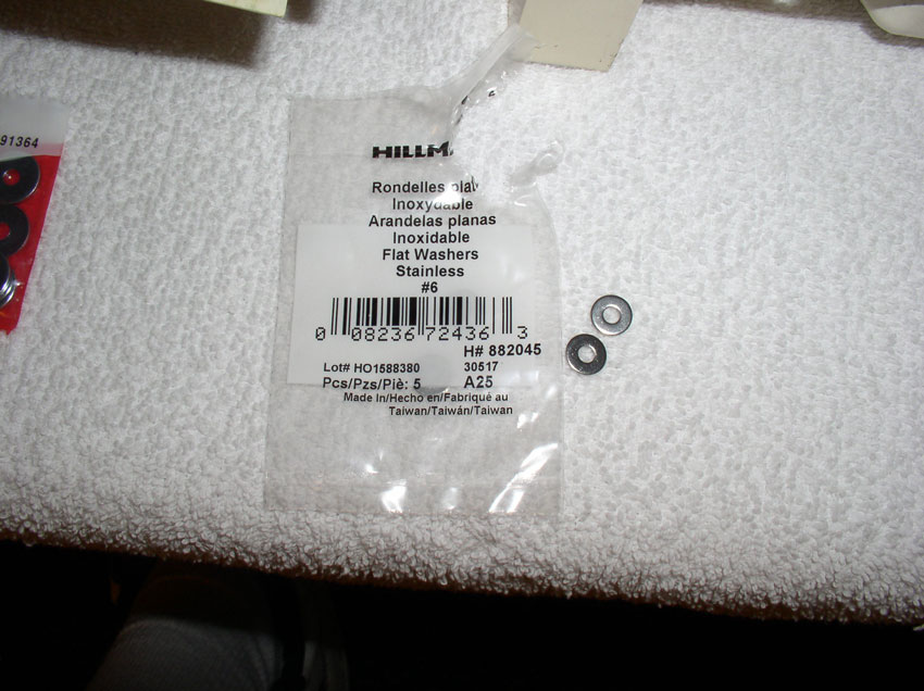
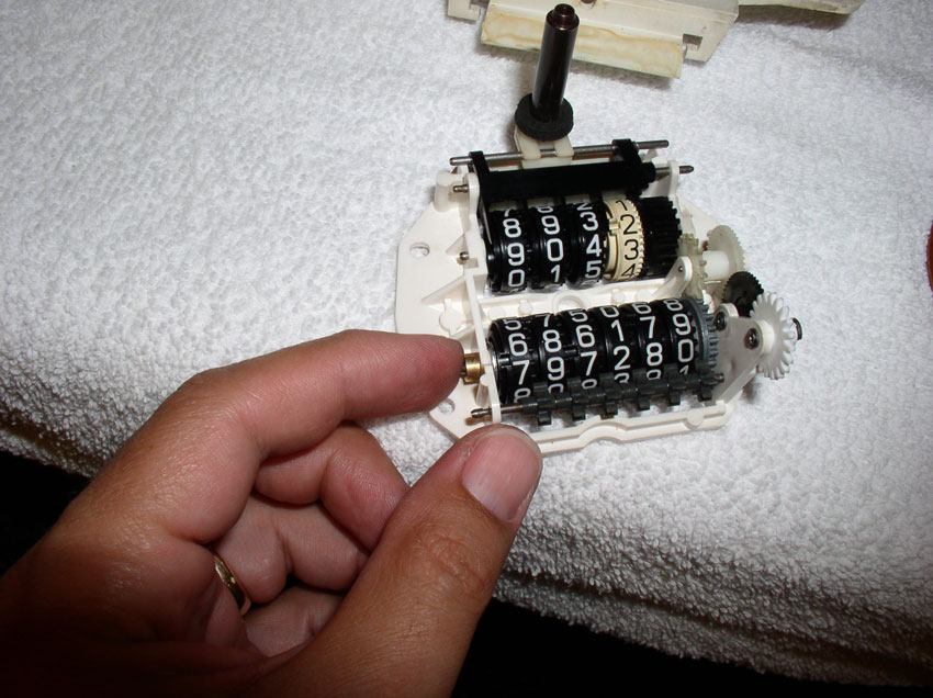
Since I didn't know exactly how much of a gap I needed to address, I purchased a few different types of small thin washers expecting one would be about right. These washers seemed to work the best. They are #6 washers from Lowe's and measure approx. 0.89mm thick. You won't know exactly what size washer will work until you test fit the washer on the odo tumbler shaft with the tumblers assembled. We'll do that next.
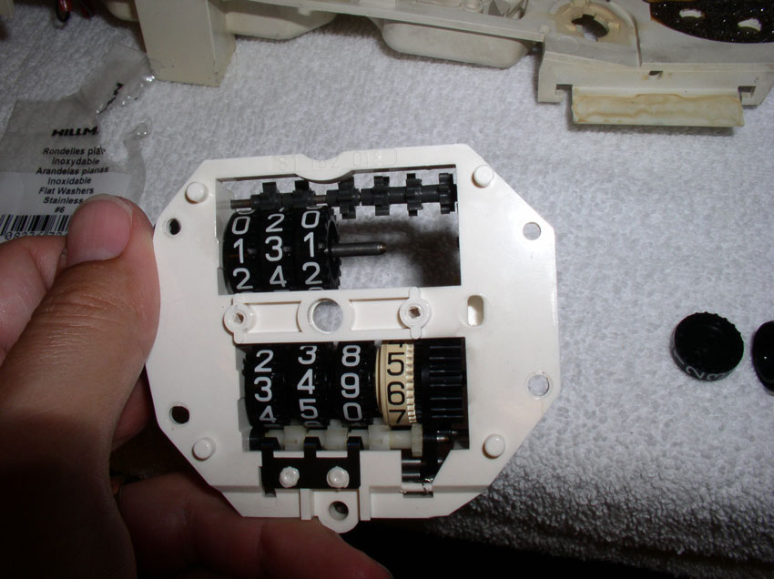
Place the washer on the end of the odo tumbler shaft (the end where the 100,000 tumbler is) as shown.

Then place the first tumbler on the shaft (the 100,000 value tumbler).
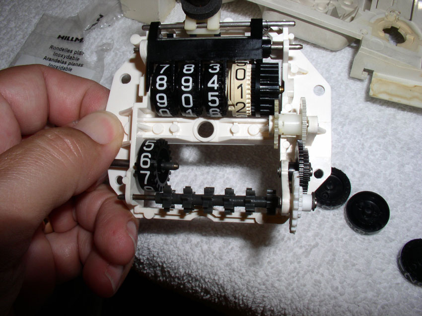
Followed by the next tumbler (10,000 value). You will notice the string of gears below the tumblers in the picture below. These gears are positioned between each of the tumblers and are designed to turn the next higher tumbler when adjacent tumbler transitions from "9" to "0". It is important that these "transition" gears are positioned between each of the tumblers as you add tumblers on the shaft.
Add the next tumbler (1,000 value)
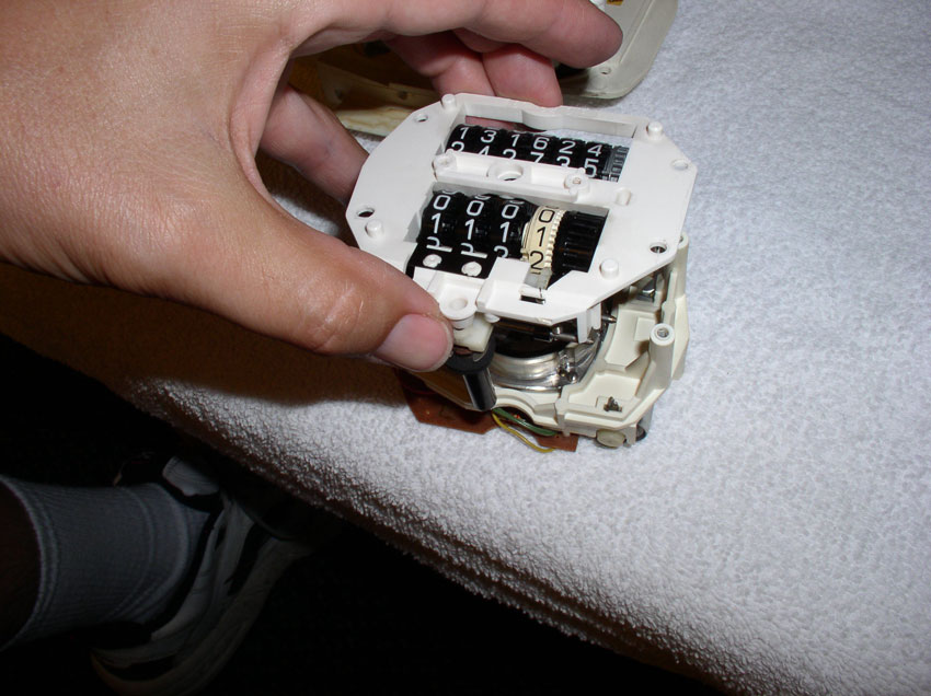
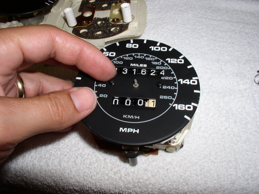
At this point, you can turn the assembly over and begin setting the mileage to the correct amount (accounting for missing mileage). This is easily done by simply rotating the third tumbler forward or backward until the highest three tumblers are set to the right mileage.
Add the next tumbler (100's) ensuring the transition gear is properly positioned between tumblers and the correct mileage value is visible.
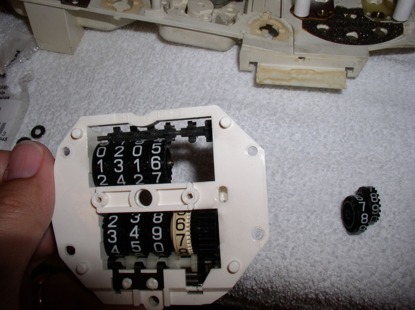
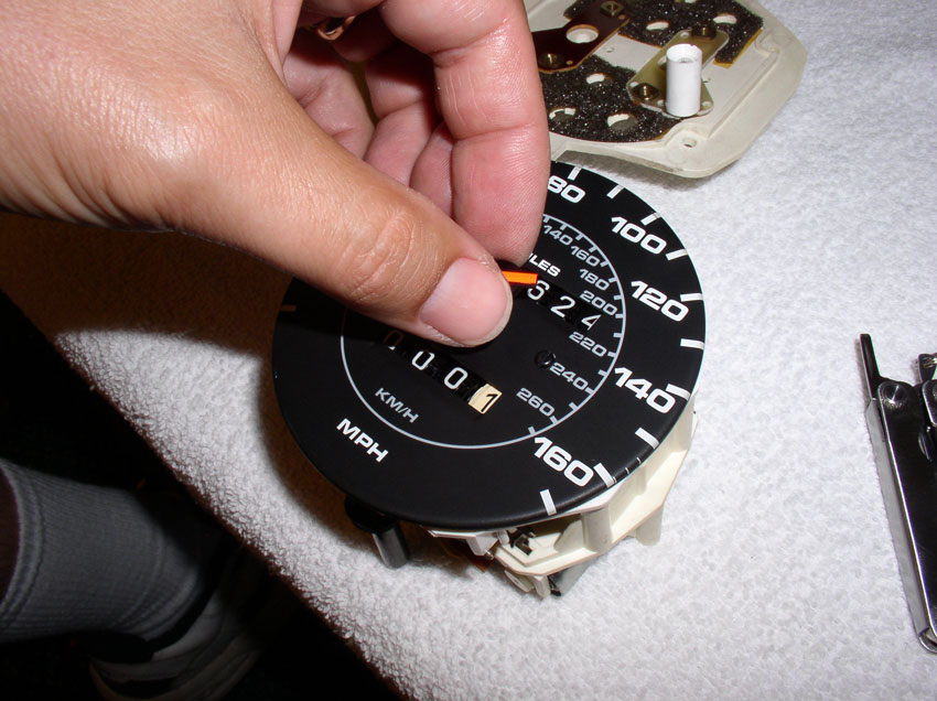
Add the last two tumblers (10's and 1's) ensuring the transition gear is properly aligned and mileage is correct. At this point, make sure the numbers on the tumblers align. While I was assembling the tumblers, it was possible to assemble the tumbler so that it was sort of half-way transitioned to the next number. To keep the tumblers from spinning while assembling, I used one hand to hold the tumblers in place (once the numbers were aligned) while I added tumblers.
After the tumblers are in and aligned, slide the tumbler drive gear between the last tumbler and the odometer housing as shown. It's at this point you will discover whether the washer added is too big or not. If you have to force the drive gear into place, it's probably too tight and you should try a thinner washer. The goal is to have no slack between the tumblers but at the same time allow the tumblers to spin freely without force.

If the driver gear slides into place without significant force, the washer is about the right size. Double check to ensure the numbers on the tumblers are aligned as shown.
Continued.....
Fully remove the shaft/pin while the tumblers are face down on the table as shown.
Then lift the odometer assembly and the tumblers should remain on the table as shown.
Since I didn't know exactly how much of a gap I needed to address, I purchased a few different types of small thin washers expecting one would be about right. These washers seemed to work the best. They are #6 washers from Lowe's and measure approx. 0.89mm thick. You won't know exactly what size washer will work until you test fit the washer on the odo tumbler shaft with the tumblers assembled. We'll do that next.
Place the washer on the end of the odo tumbler shaft (the end where the 100,000 tumbler is) as shown.
Then place the first tumbler on the shaft (the 100,000 value tumbler).
Followed by the next tumbler (10,000 value). You will notice the string of gears below the tumblers in the picture below. These gears are positioned between each of the tumblers and are designed to turn the next higher tumbler when adjacent tumbler transitions from "9" to "0". It is important that these "transition" gears are positioned between each of the tumblers as you add tumblers on the shaft.
Add the next tumbler (1,000 value)
At this point, you can turn the assembly over and begin setting the mileage to the correct amount (accounting for missing mileage). This is easily done by simply rotating the third tumbler forward or backward until the highest three tumblers are set to the right mileage.
Add the next tumbler (100's) ensuring the transition gear is properly positioned between tumblers and the correct mileage value is visible.
Add the last two tumblers (10's and 1's) ensuring the transition gear is properly aligned and mileage is correct. At this point, make sure the numbers on the tumblers align. While I was assembling the tumblers, it was possible to assemble the tumbler so that it was sort of half-way transitioned to the next number. To keep the tumblers from spinning while assembling, I used one hand to hold the tumblers in place (once the numbers were aligned) while I added tumblers.
After the tumblers are in and aligned, slide the tumbler drive gear between the last tumbler and the odometer housing as shown. It's at this point you will discover whether the washer added is too big or not. If you have to force the drive gear into place, it's probably too tight and you should try a thinner washer. The goal is to have no slack between the tumblers but at the same time allow the tumblers to spin freely without force.
If the driver gear slides into place without significant force, the washer is about the right size. Double check to ensure the numbers on the tumblers are aligned as shown.
Continued.....

The following users liked this post:
rdwalker (06-17-2024)
08-28-2009, 03:29 AM
#17
Intermediate
Thank you so much for this excellent write-up Dwayne.
I`ve just ordered odo-meter repair-kit from rennbay and will follow your procedure during my winter-projects.
I`ve just ordered odo-meter repair-kit from rennbay and will follow your procedure during my winter-projects.
08-28-2009, 10:39 AM
#19
Three Wheelin'
Thread Starter
Join Date: Sep 2007
Location: Ridgecrest, California
Posts: 1,363
Likes: 0
Received 149 Likes
on
33 Posts
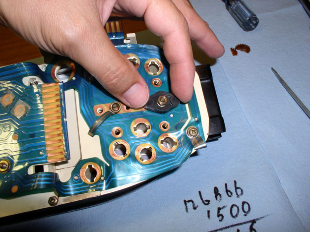
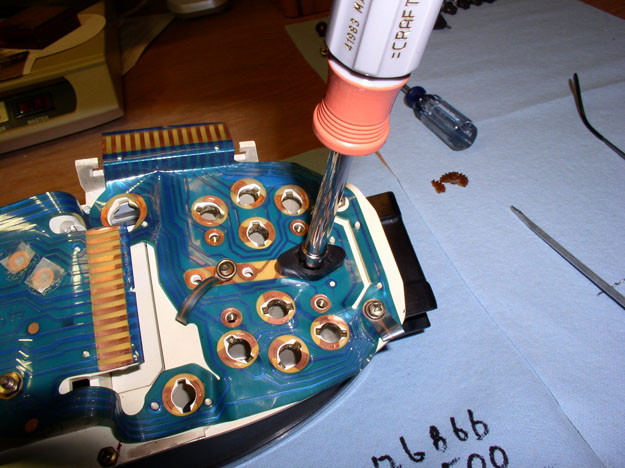
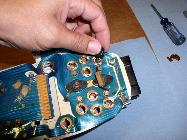
Next, re-insert the odo tumbler shaft/pin and press it all the way in flush as shown. You will have to manuever the far end of the shaft to line up with the hole in the housing in order to get the shaft in all the way. At this point, you can test the whole operation by turning the new odometer gear we replaced earlier. By turning this gear, you should see both the trip meter and odometer tumblers move. Ensure the gear and tumblers operate smoothly and without force (i.e., you should not be encountering any significant resistance). I manually ran it forward about 100 miles and back again.
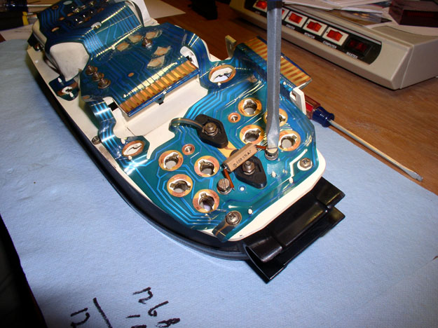
Now you can reassemble the odo tumbler portion of the unit and the electronic portion together. Carefully lower the tumbler portion onto the electronic portion as shown.
Insert the 4 screws and tighten them down. With the screws tightened down, you can spin the worm gear on the odometer motor and verify everything still moves as it should (I manually ran it up a couple of miles and back again by moving the worm gear with my finger). Everything checked out.

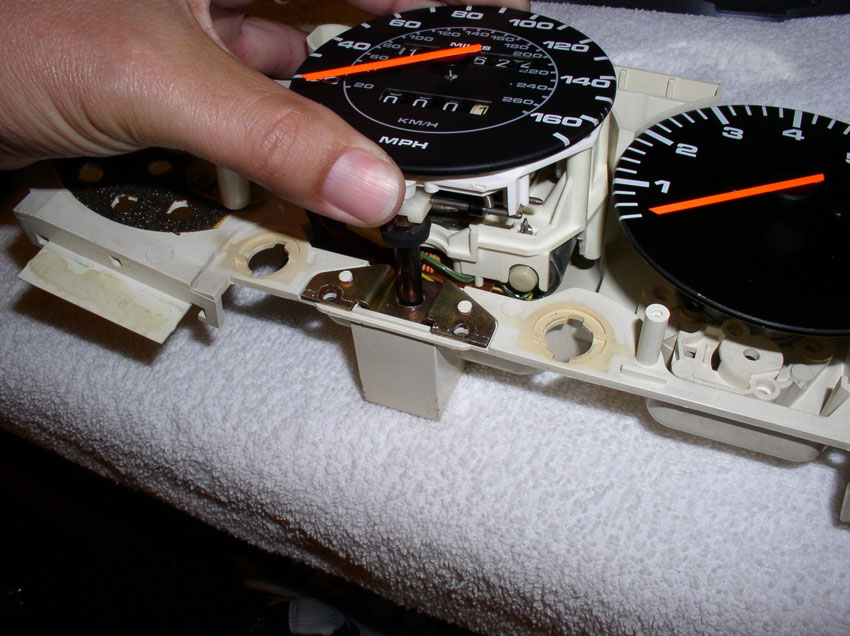
Next, replace the speedo face plate oriented as shown.
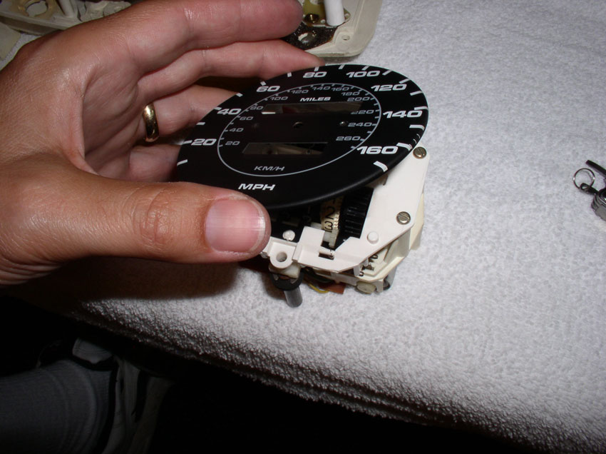
Insert the 2 securing screws and tighten them down.
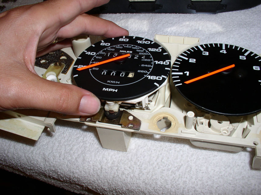
Next, grasp the speedo needle by the black plastic center hub and line it up over the same position on the face plate when it was removed earlier. My needle was lined up directly over the first tick mark on the face plate. Then, gently press down evenly on the needle hub but don't use excessive force - the speedo shaft the that needle hub rests on can easily bend. Once the needle hub is started on the shaft, I spin the needle to ensure it is installed level on the speedo shaft. In order to get it to fully seat on the speed shaft and be straight, I would gently rock and press down on the black needle hub until I had it just right. Spin the needle over the full range of motion to check for proper operation.
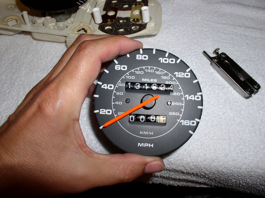
When finished, it looked just like it did before disassembly.
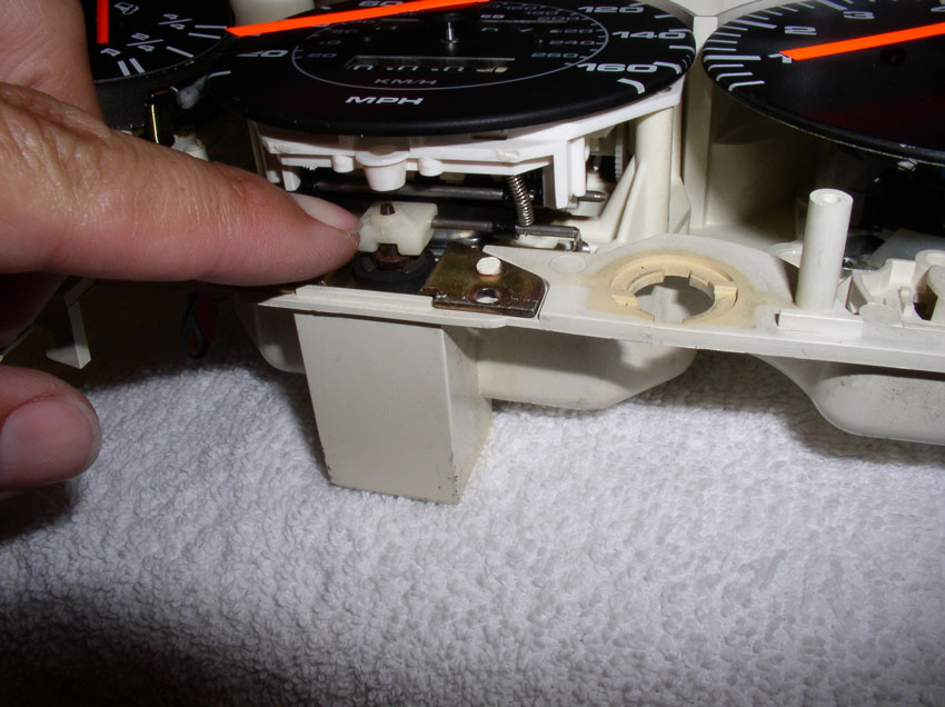
Now you can re-insert the spedo/odo unit back into the instrument housing. Line up the odometer reset magnetic cylinder so that it falls into it's housing as pictured below.
Lower the unit into the housing until it is fully seated as shown.
Check for proper operation of the odometer reset mechanism by pressing down on the lever arm as shown and the trip tumblers should reset to all "0"s. The reset mechanism should operate smoothly.
Continued.....
Now you can reassemble the odo tumbler portion of the unit and the electronic portion together. Carefully lower the tumbler portion onto the electronic portion as shown.
Insert the 4 screws and tighten them down. With the screws tightened down, you can spin the worm gear on the odometer motor and verify everything still moves as it should (I manually ran it up a couple of miles and back again by moving the worm gear with my finger). Everything checked out.
Next, replace the speedo face plate oriented as shown.
Insert the 2 securing screws and tighten them down.
Next, grasp the speedo needle by the black plastic center hub and line it up over the same position on the face plate when it was removed earlier. My needle was lined up directly over the first tick mark on the face plate. Then, gently press down evenly on the needle hub but don't use excessive force - the speedo shaft the that needle hub rests on can easily bend. Once the needle hub is started on the shaft, I spin the needle to ensure it is installed level on the speedo shaft. In order to get it to fully seat on the speed shaft and be straight, I would gently rock and press down on the black needle hub until I had it just right. Spin the needle over the full range of motion to check for proper operation.
When finished, it looked just like it did before disassembly.
Now you can re-insert the spedo/odo unit back into the instrument housing. Line up the odometer reset magnetic cylinder so that it falls into it's housing as pictured below.
Lower the unit into the housing until it is fully seated as shown.
Check for proper operation of the odometer reset mechanism by pressing down on the lever arm as shown and the trip tumblers should reset to all "0"s. The reset mechanism should operate smoothly.
Continued.....
08-28-2009, 11:42 PM
#20
Three Wheelin'
Thread Starter
Join Date: Sep 2007
Location: Ridgecrest, California
Posts: 1,363
Likes: 0
Received 149 Likes
on
33 Posts
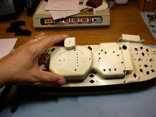
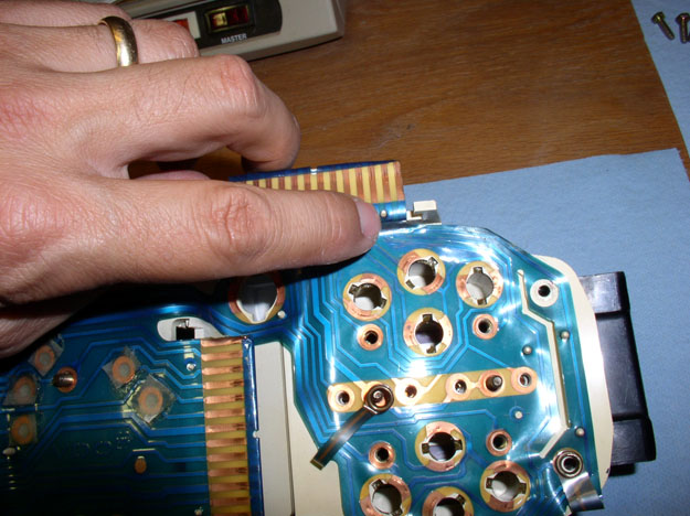
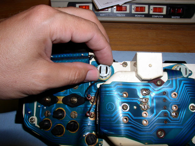
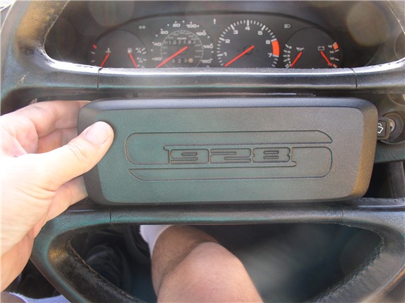
Next, if you DID NOT remove the plastic printed circuit board on the back of the instrument cluster earlier, you only need to replace the plastic instrument face cover over the instrument guages as shown....
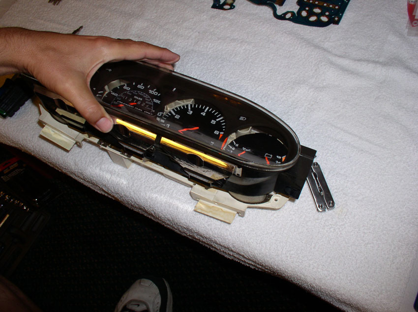
Then turn over the the instrument cluster and secure the face plate to the cluster housing using the perimeter screws as shown.
And finally, secure the speedo/odo unit to the cluster housing using the 4 small phillps screws as shown and the instrument cluster is ready to go back into the pod/car.
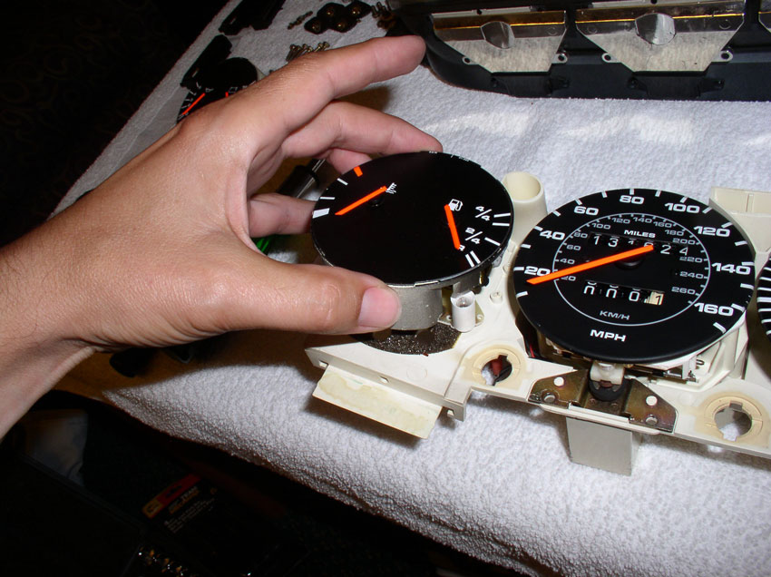
However, if you did remove the plastic circuit board, you'll need to reassemble the cluster as follows: First, place the temperature/fuel guage and oil pressure/alternator guage back into the instrument cluster as pictured.
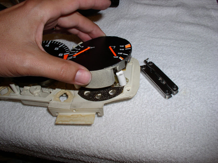
Then set the plastic cover plate over the instrumentation guages as shown.
Turn the instrument cluster face down as pictured.
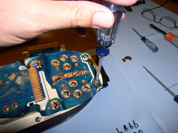
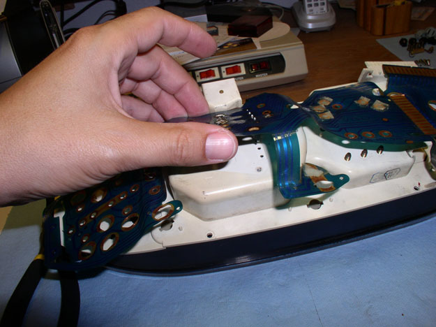
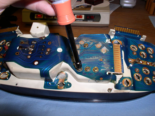
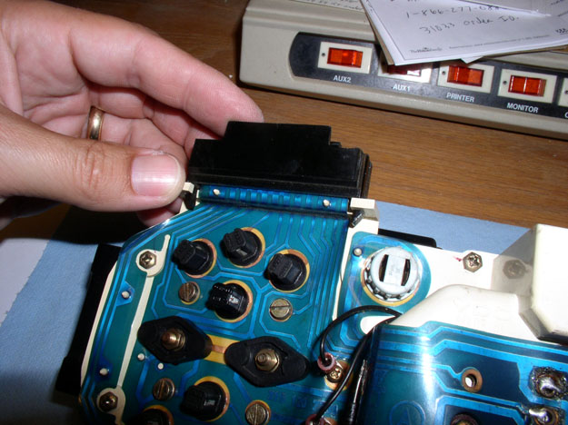
Begin re-attaching the plastic cicuit board to the back of the cluster housing. Start by lining up the speedo hard circuit board pins (4 of them) with the holes in the back of the cluster housing as shown below. Then press the hard circuit card down so it is flush with the back of the cluster housing.
Secure the hard circuit card for the speedo to the cluster housing using the 2 small phillips screws as shown.
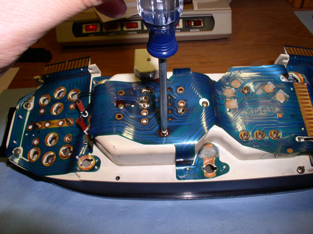
Next, begin lining up the small holes in the plastic circuit board with the guide pins in the back of the cluster housing. Press the plastic material over the guide pins.
Secure all the plastic material using these guide pins over the back of the cluster housing.
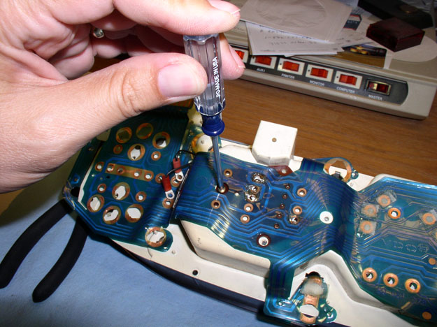
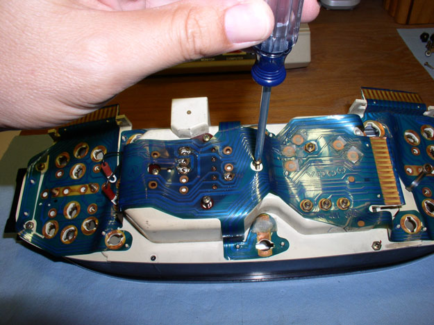
Install and tighten the tachometer contact nuts using the 7mm nut driver
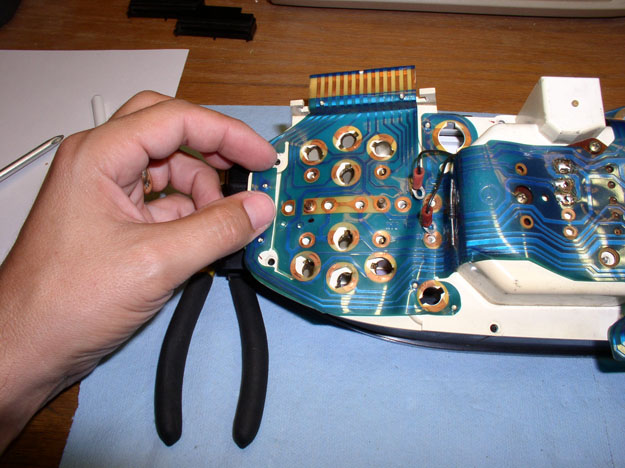
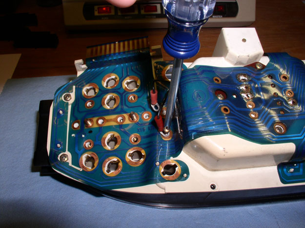
Then secure the instrument face plate to the cluster housing using the perimeter screws as shown. In the one corner, don't forget to include the lapped plastic connector under the screw as pictured below.
Next, finish attaching the speedo unit to the cluste housing using the small phillips screws
Then re-attach the odometer reset contact leads using the 2 phillips screws.
Continued.....
Then turn over the the instrument cluster and secure the face plate to the cluster housing using the perimeter screws as shown.
And finally, secure the speedo/odo unit to the cluster housing using the 4 small phillps screws as shown and the instrument cluster is ready to go back into the pod/car.
However, if you did remove the plastic circuit board, you'll need to reassemble the cluster as follows: First, place the temperature/fuel guage and oil pressure/alternator guage back into the instrument cluster as pictured.
Then set the plastic cover plate over the instrumentation guages as shown.
Turn the instrument cluster face down as pictured.
Begin re-attaching the plastic cicuit board to the back of the cluster housing. Start by lining up the speedo hard circuit board pins (4 of them) with the holes in the back of the cluster housing as shown below. Then press the hard circuit card down so it is flush with the back of the cluster housing.
Secure the hard circuit card for the speedo to the cluster housing using the 2 small phillips screws as shown.
Next, begin lining up the small holes in the plastic circuit board with the guide pins in the back of the cluster housing. Press the plastic material over the guide pins.
Secure all the plastic material using these guide pins over the back of the cluster housing.
Install and tighten the tachometer contact nuts using the 7mm nut driver
Then secure the instrument face plate to the cluster housing using the perimeter screws as shown. In the one corner, don't forget to include the lapped plastic connector under the screw as pictured below.
Next, finish attaching the speedo unit to the cluste housing using the small phillips screws
Then re-attach the odometer reset contact leads using the 2 phillips screws.
Continued.....
08-28-2009, 11:56 PM
#21
Three Wheelin'
Thread Starter
Join Date: Sep 2007
Location: Ridgecrest, California
Posts: 1,363
Likes: 0
Received 149 Likes
on
33 Posts
Next, install the guage pins and 7mm nuts on all four of the guages as shown. Remember the oil pressure guage also has a lapped plastic connector to be located under the 7mm nut (you can see it located next to my thumb in the picture below).
Tighten down the pins with the 7mm nut driver.
Next, install the 68 ohm resistor over the alternator contact screws and secure it with the two flat blade screws.
Install the remaining guage contact screws - 2 flat blade screws per guage.

Re-install the small warning lights. Insert the light fixture and rotate clockwise 90 degrees.
Next, install the instrument cluster lighting bulbs (3 of them). Insert the bulbs and rotate clockwise 90 degrees.
Finally, re-install the harness connector locking covers (3 of them). Ensure the locking prongs are engaged with the cluster housing as shown.
Now the instrument cluster is ready to be installed in the pod/car.
Continued......
Tighten down the pins with the 7mm nut driver.
Next, install the 68 ohm resistor over the alternator contact screws and secure it with the two flat blade screws.
Install the remaining guage contact screws - 2 flat blade screws per guage.
Re-install the small warning lights. Insert the light fixture and rotate clockwise 90 degrees.
Next, install the instrument cluster lighting bulbs (3 of them). Insert the bulbs and rotate clockwise 90 degrees.
Finally, re-install the harness connector locking covers (3 of them). Ensure the locking prongs are engaged with the cluster housing as shown.
Now the instrument cluster is ready to be installed in the pod/car.
Continued......
08-29-2009, 12:12 AM
#22
Addict
Rennlist Member
Rennlist Member
Dwayne, you're the man! Always a great writeup. Could you do me a favor and take apart your car and then reassemble it with pics and writeup...It would save me tons of money and aggravation.
08-29-2009, 12:31 AM
#23
Three Wheelin'
Thread Starter
Join Date: Sep 2007
Location: Ridgecrest, California
Posts: 1,363
Likes: 0
Received 149 Likes
on
33 Posts
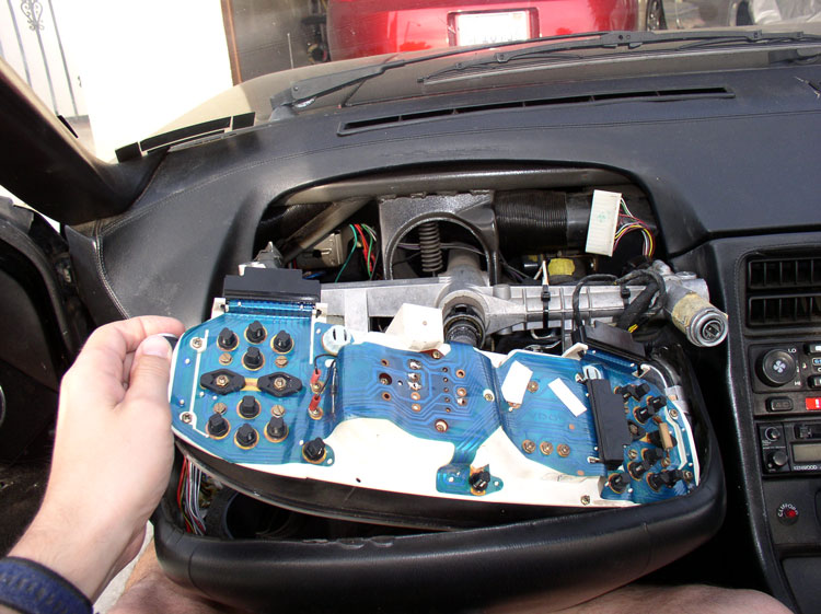
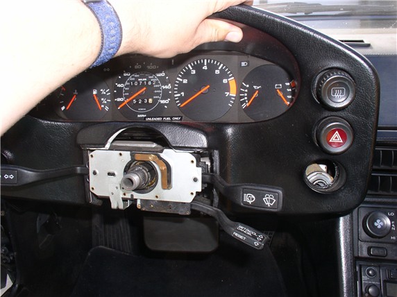
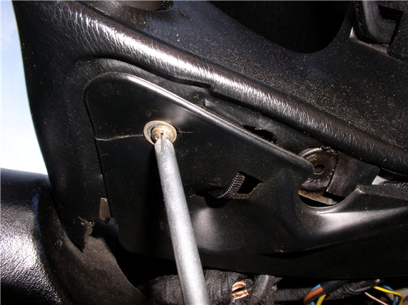
To re-install the instrument cluster back into the pod is basically the reverse procedure of taking it out. I've included the pics here for reference. First, lift up the left side of the cluster while inserting the right side into the pod - there is a moulded receiver that fits over the allen head bolt guide bushings (see pic below).
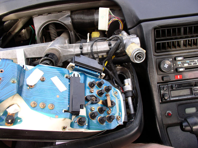
Next, ensure the left side allen bolt guide bushings are installed in the instrument cluster housing receiver....
Then, lower the left side of the cluster into the pod cavity as shown.

Whle holding the cluster in place with one hand, rotate the pod forward.....
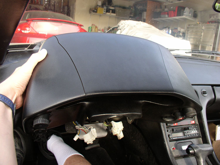
....and up over the steering column as shown.
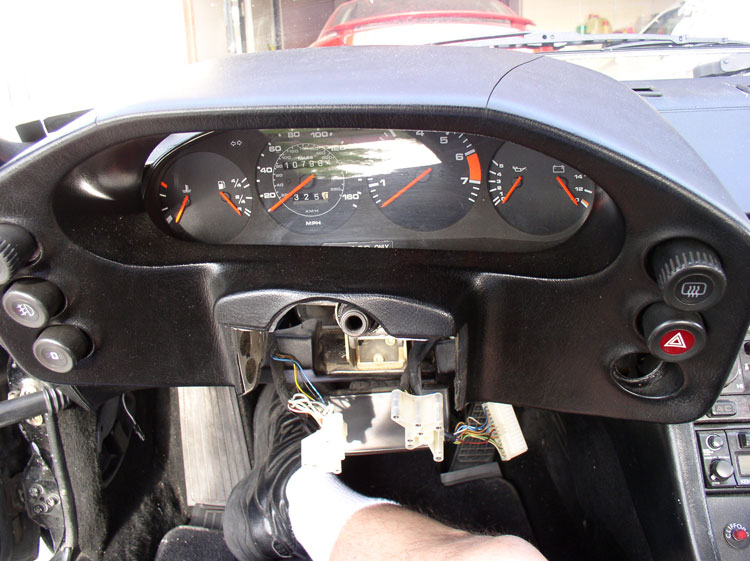
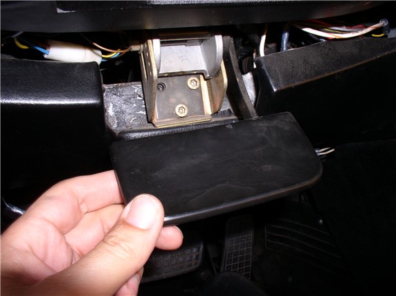
Then, before setting the pod in place, re-attach the rear wiring harness to the cluster connector. Push the harness into the connector until is locks into place. Then push the pod back into place against the dash.
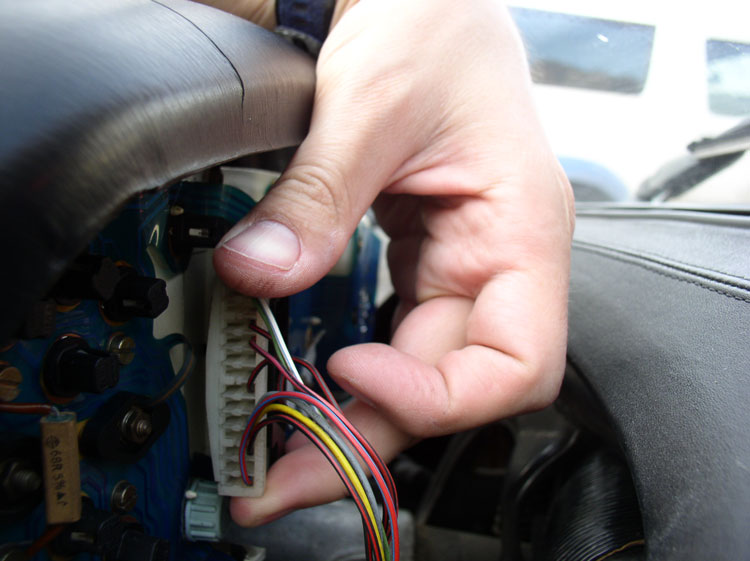
Next, connect the two lower harness connectors (left and right) underneath the pod as pictured.
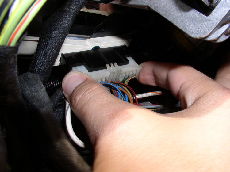
Then install the signal/wiper/cuise cluster by slipping it on over the steering column and pushing it far enough down the column that you can connect the two keyed harness connectors.
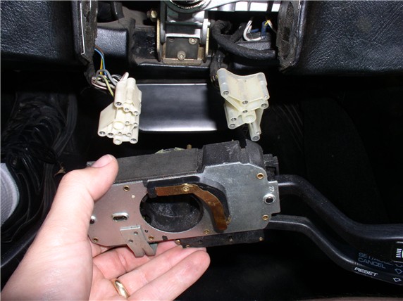
Lifting up the pod slightly, continue pushing/walking the signal/wiper/cruise cluster down the steering column until it clears the portion of the pod that fits over the cluster.

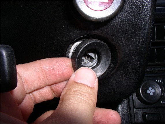
Then, lower the pod and line up the ignition switch hole with the ignition switch and push the pod back over the ignition switch.
Next, install the ignition switch grommet.
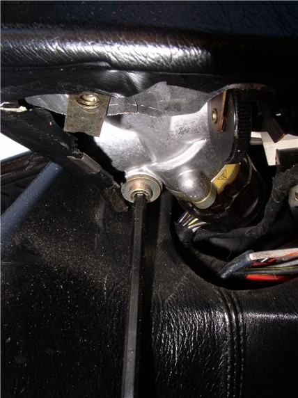
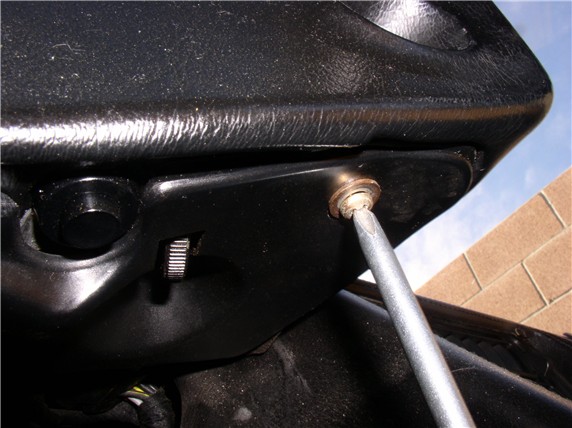
Recall that the long allen bolt secures the left side of the pod and the shorter bolt secures the right.

Install the left side allen bolt as shown. You may have to slightly manuever the pod to line up the bolt guide bushings with the metal flange on the dash framing.

Next, install the right side allen bolt in the same manner.
Continued......
Next, ensure the left side allen bolt guide bushings are installed in the instrument cluster housing receiver....
Then, lower the left side of the cluster into the pod cavity as shown.
Whle holding the cluster in place with one hand, rotate the pod forward.....
....and up over the steering column as shown.
Then, before setting the pod in place, re-attach the rear wiring harness to the cluster connector. Push the harness into the connector until is locks into place. Then push the pod back into place against the dash.
Next, connect the two lower harness connectors (left and right) underneath the pod as pictured.
Then install the signal/wiper/cuise cluster by slipping it on over the steering column and pushing it far enough down the column that you can connect the two keyed harness connectors.
Lifting up the pod slightly, continue pushing/walking the signal/wiper/cruise cluster down the steering column until it clears the portion of the pod that fits over the cluster.
Then, lower the pod and line up the ignition switch hole with the ignition switch and push the pod back over the ignition switch.
Next, install the ignition switch grommet.
Recall that the long allen bolt secures the left side of the pod and the shorter bolt secures the right.
Install the left side allen bolt as shown. You may have to slightly manuever the pod to line up the bolt guide bushings with the metal flange on the dash framing.
Next, install the right side allen bolt in the same manner.
Continued......
08-29-2009, 01:00 AM
#24
Three Wheelin'
Thread Starter
Join Date: Sep 2007
Location: Ridgecrest, California
Posts: 1,363
Likes: 0
Received 149 Likes
on
33 Posts
Next, you will need to locate the final resting position of the signal/wiper/cruise cluster so that the horn contact does not have too much pressure but also makes light contact. Place the steering wheel back onto the steering column and seat it all the way down. Then inspect the horn contact on the wheel making contact with the spring contact on the cluster. The steering wheel horn contact should just barely make contact with the spring contact on the cluster. You can watch for it as you slide the wheel on to the steering column. Move the signal/wiper/cruise cluster up or down the column to get the right contact. Too heavy of a contact will result in a scraping sound when turning the steering wheel and no contact will result in the horn not working. After you've finally positioned the cluster, remove the steering wheel. If your signal/wiper/cruise cluster had a clamping bolt on it, now's the time to tighten the bolt down to secure the cluster to the steering column. Mine did have the clamp but no bolt. Then attach the lower cluster cover as shown.
Secure the cover with the phillps screw.....
...and the two 10mm bolts.
Next, position the lower plastic pod cover plate by inserting the prongs first then sliding the cover forward to lock it into place.
Then secure the cover plate with the two phillips screws - one at each end.
Raise the tilt wheel paddle and lock it in place.
Next, you'll attach the steering wheel. According the Technical Bulletin #9205 Titled "Noise When Turning Steering Wheel", do not apply any lubricant to the horn contact ring or contact spring strip on the cruise/signal/wiper cluster. Position the steering wheel in the same orientation as you removed it. In this case, perfectly straight.

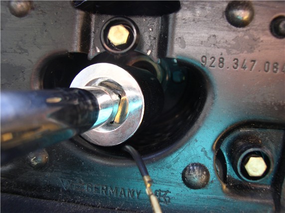
Place the washer and nut on the steering column threads and tighten the nut with the 27mm socket and ratchet using the 6" extension. Tighten to 36 Ftlbs.
Attach the horn electrical lead to the back of the horn pad as shown.
Position the horn pad so the horn pad contacts with springs ling up with the contact tabs on the steering wheel. Then press the horn pad into place until you hear/feel the tabs lock. There are three tabs so you'll want to make sure all three are locked and the pad is level with the steering wheel.
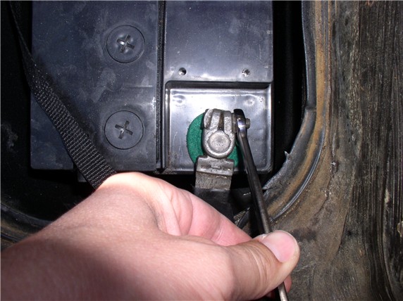
Finally, you will reconnect the negative battery cable using the 13mm combo wrench. After connecting the battery, test the horn for proper operation.
Next, you can start the car and take it for a test spin and try out the newly repaired odometer! If everthing checks out, you're done! CONGRATULATIONS!!
Please feel free to comment and recommend improvements to this post as I (and the community) welcome shortcuts and improvements on this procedure. THANKS for reading!
Secure the cover with the phillps screw.....
...and the two 10mm bolts.
Next, position the lower plastic pod cover plate by inserting the prongs first then sliding the cover forward to lock it into place.
Then secure the cover plate with the two phillips screws - one at each end.
Raise the tilt wheel paddle and lock it in place.
Next, you'll attach the steering wheel. According the Technical Bulletin #9205 Titled "Noise When Turning Steering Wheel", do not apply any lubricant to the horn contact ring or contact spring strip on the cruise/signal/wiper cluster. Position the steering wheel in the same orientation as you removed it. In this case, perfectly straight.
Place the washer and nut on the steering column threads and tighten the nut with the 27mm socket and ratchet using the 6" extension. Tighten to 36 Ftlbs.
Attach the horn electrical lead to the back of the horn pad as shown.
Position the horn pad so the horn pad contacts with springs ling up with the contact tabs on the steering wheel. Then press the horn pad into place until you hear/feel the tabs lock. There are three tabs so you'll want to make sure all three are locked and the pad is level with the steering wheel.
Finally, you will reconnect the negative battery cable using the 13mm combo wrench. After connecting the battery, test the horn for proper operation.
Next, you can start the car and take it for a test spin and try out the newly repaired odometer! If everthing checks out, you're done! CONGRATULATIONS!!
Please feel free to comment and recommend improvements to this post as I (and the community) welcome shortcuts and improvements on this procedure. THANKS for reading!
Last edited by Dwayne; 01-03-2010 at 11:10 PM.
08-29-2009, 01:58 AM
#25
Three Wheelin'
Thread Starter
Join Date: Sep 2007
Location: Ridgecrest, California
Posts: 1,363
Likes: 0
Received 149 Likes
on
33 Posts
thanks Dwayne, your pics/procedure are much more clear than the WSM.
question, I have also read something about the elec motor that drives the ODO. since acquiring my 84 last year, the ODO started working again then stopped again. so in a addion to replacing the ODO gear, are you finding this a suggested replacement item WYAIT?
looking forward to the conclusion, this one is a keeper. add to my list of winter project.
I have not heard about the motor failing regularly and needing to replace it WYAIT. If the odometer is working intermittently, perhaps it's an intermittent electrical connection issue. If you've inspected, cleaned, repaired (soldered) the electrical connections and the odometer continues to stop working intermittently, perhaps the motor should be replaced. I would inspect/clean/repair any electrical connections first before replacing the motor. Hope this helps. THANKS for the question and the comments!
08-29-2009, 02:10 AM
#26
Three Wheelin'
Thread Starter
Join Date: Sep 2007
Location: Ridgecrest, California
Posts: 1,363
Likes: 0
Received 149 Likes
on
33 Posts
Absolutely!! I dont' want to miss a single mile. The more miles I collect on the Odo, the sooner I get to retire California and move on to my next shark as a daily driver - Oregon!
08-29-2009, 04:10 AM
#28
Addict
Rennlist Member
Rennlist Member

Join Date: Mar 2002
Location: Incline Village N. V 89451
Posts: 151
Likes: 0
Received 0 Likes
on
0 Posts
Dwayne I would like to thank You for such a great job on this fix for the odometer it is the best that I have ever seen! again Thanks Vernon.
08-29-2009, 09:54 AM
#29
Three Wheelin'
Thread Starter
Join Date: Sep 2007
Location: Ridgecrest, California
Posts: 1,363
Likes: 0
Received 149 Likes
on
33 Posts

Sounds like FUN! However, if I disassembled my car, it probably wouldn't look like a 928 when I put it back together! I'm still learning....

Thanks, Joe, and ALL for the great comments!!